Page is loading ...

200 series
reverse-osmosis systems
Installation, Operation,
and Maintenance Manual
WATER TREATMENT
READ AND SAVE THESE INSTRUCTIONS

ii
DRISTEEM WATER TREATMENT SYSTEMS INSTALLATION, OPERATION, AND MAINTENANCE MANUAL ........
WARNINGS AND CAUTIONS

iii
DRISTEEM WATER TREATMENT SYSTEMS INSTALLATION, OPERATION, AND MAINTENANCE MANUAL
Warnings and cautions
Warnings and Cautions
WARNING
Attention installer
Read this manual before installing, and leave this manual with product owner. This product must be installed by qualifi ed
HVAC and electrical contractors. Installation must be code approved.
Disconnect electrical power
Disconnect electrical power before installing supply wiring or performing service or maintenance procedures on any part
of the system. Failure to disconnect electrical power could result in fi re, electrical shock, and other hazardous conditions.
These hazardous conditions could cause property damage, personal injury, or death.
CAUTION
Operate system at above-freezing temperatures.
Operating the system at temperatures below freezing can damage the system or cause other property damage.
Maintain pumping and water treatment equipment.
Inadequately maintained pumping and water treatment equipment can cause the system to fail. Refer to the maintenance section
of this IOM for recommended maintenance.
Do not install the system using steel or galvanized-steel piping and joints.
Steel and steel-galvanized piping and joints can corrode and cause system damage. Use plastic tubing and joints when
assembling system.
Follow all instructions in this manual to maintain product warranty.
FILL IN THE FOLLOWING INFORMATION FOR YOUR RECORDS
Date of purchase
___________________________________________________________________________________________________________
Customer's name
___________________________________________________________________________________________________________
Model number
___________________________________________________________________________________________________________
Serial number
___________________________________________________________________________________________________________

iv
DRISTEEM WATER TREATMENT SYSTEMS INSTALLATION, OPERATION, AND MAINTENANCE MANUAL ........
WARNINGS AND CAUTIONS . . . . . . . . . . . . . . . . . . . . . . . . . . . . . . . . . . . . . . . . . . . . . . . . ii
Fill in the following information for your records . . . . . . . . . . . . . . . . .iii
ATTENTION INSTALLER . . . . . . . . . . . . . . . . . . . . . . . . . . . . . . . . . . 1
Where to find more information . . . . . . . . . . . . . . . . . . . . . . . . . . . . . . 1
OVERVIEW. . . . . . . . . . . . . . . . . . . . . . . . . . . . . . . . . . . . . . . . . . . . . . . . . . . . . . . . . . . . . . 2
System specifications . . . . . . . . . . . . . . . . . . . . . . . . . . . . . . . . . . . . 2
Flow schematic . . . . . . . . . . . . . . . . . . . . . . . . . . . . . . . . . . . . . . . . 3
Component identification . . . . . . . . . . . . . . . . . . . . . . . . . . . . . . . . . 4
System installation . . . . . . . . . . . . . . . . . . . . . . . . . . . . . . . . . . . . . . 5
Line 1 . . . . . . . . . . . . . . . . . . . . . . . . . . . . . . . . . . . . . . . . . . . . . . 5
Line 2 . . . . . . . . . . . . . . . . . . . . . . . . . . . . . . . . . . . . . . . . . . . . . . 5
Line 3 . . . . . . . . . . . . . . . . . . . . . . . . . . . . . . . . . . . . . . . . . . . . . . 5
Line 4 . . . . . . . . . . . . . . . . . . . . . . . . . . . . . . . . . . . . . . . . . . . . . . 5
Line 5 . . . . . . . . . . . . . . . . . . . . . . . . . . . . . . . . . . . . . . . . . . . . . . 5
Pre-treatment connection . . . . . . . . . . . . . . . . . . . . . . . . . . . . . . . 6
Series 200 controller specifications . . . . . . . . . . . . . . . . . . . . . . . . . . 6
Power . . . . . . . . . . . . . . . . . . . . . . . . . . . . . . . . . . . . . . . . . . . 6
Inputs . . . . . . . . . . . . . . . . . . . . . . . . . . . . . . . . . . . . . . . . . . . . 6
Outputs . . . . . . . . . . . . . . . . . . . . . . . . . . . . . . . . . . . . . . . . . . 6
RO pump wiring . . . . . . . . . . . . . . . . . . . . . . . . . . . . . . . . . . . . . . . 8
Inlet wiring . . . . . . . . . . . . . . . . . . . . . . . . . . . . . . . . . . . . . . . . . . . 8
Pressure fault switch . . . . . . . . . . . . . . . . . . . . . . . . . . . . . . . . . . . . . 8
Pretreat switch . . . . . . . . . . . . . . . . . . . . . . . . . . . . . . . . . . . . . . . . . 8
Tank full switch . . . . . . . . . . . . . . . . . . . . . . . . . . . . . . . . . . . . . . . . 8
OPERATION . . . . . . . . . . . . . . . . . . . . . . . . . . . . . . . . . . . . . . . . . . . . . . . . . . . . . . . . . . . . . 9
System operation . . . . . . . . . . . . . . . . . . . . . . . . . . . . . . . . . . . . . . . 9
System operation continued . . . . . . . . . . . . . . . . . . . . . . . . . . . . . . 10
Initial system start-up . . . . . . . . . . . . . . . . . . . . . . . . . . . . . . . . . . . 10
System flush . . . . . . . . . . . . . . . . . . . . . . . . . . . . . . . . . . . . . . 10
Normal operations . . . . . . . . . . . . . . . . . . . . . . . . . . . . . . . . . . . . 10
Shutdown . . . . . . . . . . . . . . . . . . . . . . . . . . . . . . . . . . . . . . . . . . . 10
Table of contents

1
DRISTEEM WATER TREATMENT SYSTEMS INSTALLATION, OPERATION, AND MAINTENANCE MANUAL
Table of contents
ATTENTION INSTALLER
Read this manual before installing.
Leave manual with product owner.
DriSteem
®
Technical Support
800-328-4447
WHERE TO FIND MORE INFORMATION
Our website:
The following documents are available on our
web site: www.dristeem.com
• Water Treatment Systems Catalog
• Vapor-logic Controller Installation and
Operation Manual
DriCalc
®
:
DriCalc, our software for system sizing and
selection, can be ordered at our web site.
Call us at 800-328-4447
Obtaining documents from our web site or
from DriCalc is the quickest way to view our
literature, or we will be happy to mail literature
to you.
Download DriSteem literature
Most DriSteem product manuals are available
our website: www.dristeem.com
MAINTENANCE . . . . . . . . . . . . . . . . . . . . . . . . . . . . . . . . . . . . . . . . . . . . . . . . . . . . . . . .
11
Maintenance information . . . . . . . . . . . . . . . . . . . . . . . . . . . . . . . . 11
Maintenance tips . . . . . . . . . . . . . . . . . . . . . . . . . . . . . . . . . . . . . . 11
When to change cartridge filters . . . . . . . . . . . . . . . . . . . . . . . . . . . 11
When to clean membranes . . . . . . . . . . . . . . . . . . . . . . . . . . . . . . . 11
Membrane cleaning and preservative cartridges . . . . . . . . . . . . . 11
Membrane cleaning in the RO system . . . . . . . . . . . . . . . . . . . . . . . 12
How does it work? . . . . . . . . . . . . . . . . . . . . . . . . . . . . . . . . . . . . 12
Scale cleaning cartridge. . . . . . . . . . . . . . . . . . . . . . . . . . . . . . . . . 12
Cleaning procedure . . . . . . . . . . . . . . . . . . . . . . . . . . . . . . . . . 12
Organic cleaning cartridge . . . . . . . . . . . . . . . . . . . . . . . . . . . . . . 13
Cleaning procedure . . . . . . . . . . . . . . . . . . . . . . . . . . . . . . . . . 13
Membrane preservative cartridge . . . . . . . . . . . . . . . . . . . . . . . . . . 14
Preserving procedure . . . . . . . . . . . . . . . . . . . . . . . . . . . . . . . . 14
Flushing out preservative/restart procedure . . . . . . . . . . . . . . . . 14
Tools . . . . . . . . . . . . . . . . . . . . . . . . . . . . . . . . . . . . . . . . . . . 15
Procedure . . . . . . . . . . . . . . . . . . . . . . . . . . . . . . . . . . . . . . . . 15
Procedure . . . . . . . . . . . . . . . . . . . . . . . . . . . . . . . . . . . . . . . . 16
Tools . . . . . . . . . . . . . . . . . . . . . . . . . . . . . . . . . . . . . . . . . . . . . . 17
Low pressure cut-out switch . . . . . . . . . . . . . . . . . . . . . . . . . . . . . . . 17
Operating do's and don'ts . . . . . . . . . . . . . . . . . . . . . . . . . . . . . . . 17
Do . . . . . . . . . . . . . . . . . . . . . . . . . . . . . . . . . . . . . . . . . . . . . 17
Don't . . . . . . . . . . . . . . . . . . . . . . . . . . . . . . . . . . . . . . . . . . . 17
WARRANTY . . . . . . . . . . . . . . . . . . . . . . . . . . . . . . . . . . . . . . . . . . . . . . . . . . . . . . . . . . . 20

2
DRISTEEM WATER TREATMENT SYSTEMS INSTALLATION, OPERATION, AND MAINTENANCE MANUAL ........
System specifi cations
OVERVIEW
NOTES:
1. All systems rated at 50°F (10°C) using 1000 ppm sodium chloride (NaCl)
solution. System capacity decreased signifi cantly with decrease in feed
water temperature.
2. Chlorine requirements for the feed water are:
a. Thin-Film (standard) 0 ppm
3. Feed water must be filtered to a turbidity of less than 1 NTU.
4. System recovery (permeate to concentrate ratio) must be maintained at
the recommended level. A higher than recommended recovery will lead
to a premature fouling of the membrane with a loss of permeate flow and
permeate quality.
Table 2-1:
Pressurized RO holding tank specifications
Model Hz Motor HP Volts*/Amps Phase/Frequency
201
202
203
60 1/3
110-120 VAC/5.5A
(208-240 VAC/2.8A)
1/60Hz
* 115V or 230V must be ordered specifi cally
Table 2-2:
RO station specifications
Model 201 202 203
Rated capacity, permeate
Gallons/minute 0.2 0.4 0.6
Concentrate fl ow (reject)
Gallons/minute 1.1 1.2 0.97
Recirc (adjustable as needed)
Gallons/minute 0 - 1.0 0 - 1.0 0 - 0.8
System pressure, psi 100 - 150 100 - 150 100 - 150
°F (°C) 10/50 10/50 10/50
Pre-fi lters
Sediment cartridge - 5 micron 1 1 1
Carbon cartridge - 10 micron 1 1 1
Pressure switch settings
Low pressure (for pump protection) 8 psi 8 psi 8 psi

3
DRISTEEM WATER TREATMENT SYSTEMS INSTALLATION, OPERATION, AND MAINTENANCE MANUAL
Flow schematic
OVERVIEW
FIGURE 3-1: FLOW SCHEMATIC
OM-7822

4
DRISTEEM WATER TREATMENT SYSTEMS INSTALLATION, OPERATION, AND MAINTENANCE MANUAL ........
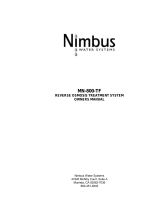
Component identifi cation
FIGURE 4-1: COMPONENT IDENTIFICATION
Table 4-2:
Component identification
Item Description
1 Controller Power On/Off and status display
2 Inlet solenoid valve Normally closed. Opens when power is applied.
3 Cartridge fi lter pressure gauges (in-right/out-left)
Measure the feed and effl uent pressure of the cartridge fi lters. Pressure difference
determines when cartridge change out is required.
4 Sediment fi lter 5 micron sediment fi lter.
5 Carbon fi lter
10 micron extruded carbon cartridge to remove chlorine and reduce organics from the feed
stream.
6 Low pressure switch Shuts the system down if the inlet pressure is lower than 8 psi (adjustable).
7 High pressure pump and motor Rotary pump and motor to pressurize the incoming water.
8 Membrane modules RO membrane elements housed in stainless steel pressure tubes.
9 System pressure gauges Measure the system (feed) and concentrate (effl uent) pressure of the membrane modules.
10 Concentrate control valve To adjust system pressure. Must not be completely closed when the system is in operation.
11 Recirc valve To adjust and maintain adequate fl ow thru membranes
12 TDS monitor
Monitors the feed and permeate water quality.
12a - feed sensor; 12b - permeate sensor
13 Permeate check valve Prevents backfl ow into RO module.
1
10
11
3
12a
5
4
2
3
9
12b
6
8
7
13
12
6
OVERVIEW

5
DRISTEEM WATER TREATMENT SYSTEMS INSTALLATION, OPERATION, AND MAINTENANCE MANUAL
INSTALLATION
System installation
1. Locate RO system with adequate clearance from walls and other
equipment to enable membrane servicing.
2. Run five polyvinyl tube lines to the system as follows:
LINE 1
Connect raw water feed supply to the solenoid valve inlet in front of the fi rst
cartridge fi lter housing. This will require ½ inch threaded pipe fi tting and
adaptor for the feed line. If desired, install an isolation valve in this line; ensure
the valve opening does not restrict the water fl ow.
LINE 2
Run a ⅜ inch line from the open end of the concentrate valve to a drain. Ensure
that no liquids from other lines near this drain fl ow back through this line.
LINE 3
Run a ⅜ inch line from one of the two permeate outlets on the back of the
system to the pressurized permeate storage container.
NOTE: The recirc fl ow line is pre-connected at the factory.
LINE 4
Run a ⅜ inch line from the other permeate outlet to the humidifi er or end
process being fed by the system.
LINE 5
Run a ¼inch line from the pressurized relief solenoid to a drain. Ensure that no
liquids from other lines near this drain fl ow back through this line.
FIGURE 5-1: SOLENOID VALVE INLET
FIGURE 5-2: RECIRC FLOW LINE
CAUTION
Pump and system performance will be
adversely affected if the feed/suction
line is restricted.
CAUTION
Confi rm all lines are connected before
plugging in unit power.

6
DRISTEEM WATER TREATMENT SYSTEMS INSTALLATION, OPERATION, AND MAINTENANCE MANUAL ........
PRE-TREATMENT CONNECTION
If you have pre-treatment equipment and you wish to shut-down the RO system
during backwash or regeneration, a microswitch is required (standard with
DriSteem water softeners).
1. Wire the microswitch to terminal labeled PreTreat inside controller.
When the equipment goes into backwash or regeneration, the pre-treat limit
switch opens and turns the power off the inlet solenoid valve, which then turns
the RO pump off (and back on) when the cycle is complete.
SERIES 200 CONTROLLER SPECIFICATIONS
POWER
Either 110-120 VAC or 208-240 VAC, 1 phase,
50/60 Hz, +10/-15%, 2.5 watts
Input power is auto selected
INPUTS
Three switch inputs, selectable normally open or normally closed
OUTPUTS
RO pump 1HP (based on service factor of 1.0 max)
Inlet solenoid 5A
20A maximum total load
NOTE: All six switches are factory set to the OFF position.
Auto reset (disabled)
Pressure fault retry (disabled)
Tank full restart time delay (two seconds)
Input contact type (NC, open to operate)
If you desire to change any switch functions, move that switch to the ON
position.
INSTALLATION
System installation
FIGURE 6-1: CONTROL BOARD
CAUTION
The controller is rated for maximum
20 amp total load. Terminal strip
P11 is dry contact for input signals
from tank full, pressure fault and
pretreat lockout. Use a small gauge
2 conductor cable for these wire
connections.
Table 6-1:
Switch positions
Switch Off position On position
1 Auto reset off Auto reset on
2 Retries disabled Retries enabled
3 2 sec. restart 15 min. restart
4 N.O switches N.C. switches
Switch 5 and 6 not used.

7
DRISTEEM WATER TREATMENT SYSTEMS INSTALLATION, OPERATION, AND MAINTENANCE MANUAL
Schematic drawing
INSTALLATION
FIGURE 7-1: CONTROLLER ELECTRICAL SCHEMATIC
OM-7821

8
DRISTEEM WATER TREATMENT SYSTEMS INSTALLATION, OPERATION, AND MAINTENANCE MANUAL ........
Control board
RO PUMP WIRING
The RO pump connects to P4 (L1) and P5 (L2) RO pump terminals. This output can operate 110/240 VAC motors up to
1HP directly.
INLET WIRING
The inlet solenoid valve connects to P6 (L1) and P7 (L2) inlet terminals.
PRESSURE FAULT SWITCH
The feed pressure switch is connected to the pressure fault input. Low pressure (factory preset 8 psi) will shut system off.
PRETREAT SWITCH
In systems with pretreatment, a pretreat lockout switch can be connected to the pretreat input. This switch should operate
when the pretreatment device is out of service.
NOTE: The output from the pretreatment device must be a dry contact and must not supply voltage.
TANK FULL SWITCH
DriSteem systems use a pressure switch to keep the pressurized storage tank between 30-50 psi (207-345 kPa). The
switch is connected to the tank full input.
INSTALLATION
FIGURE 8-1: CONTROLLER ELECTRICAL SCHEMATIC
Tank full

9
DRISTEEM WATER TREATMENT SYSTEMS INSTALLATION, OPERATION, AND MAINTENANCE MANUAL
OPERATION
The unit has a single mode of operation ON with six sub-modes or states as
indicated by the steady or fl ashing panel lights. Any light condition other than
steady power ON indicates the unit is effectively in standby-mode. If there are
no lights, the system is OFF and all outputs are turned off. In the operating
mode, the unit operates automatically. All inputs are monitored and the outputs
are controlled accordingly. Pressing the power key will toggle the unit from
off to operate or from operate to off. If power is removed from the unit when
power is reapplied, the unit will restart in the mode it was in when the power
was removed.
When the power switch is turned ON, the center status LED will light green, the
valve will open, and the RO pump will start.
Under normal operation the RO unit will run until:
a. the storage tank is full (right LED amber) or
b. pretreat lockout has occurred (center status LED fl ashing green).
When a or b has cleared after a time delay, the RO unit will restart and the
center status LED will return to green. Switch setting three selects a two second
or 15 minute tank full restart time delay.
Upon an alarm signal for pressure fault, the left status LED will fl ash red, the
RO pump will stop, and the inlet valve will close and the RO pump will turn
OFF.
• If switch one and two are in the OFF position (disabled), the left status LED
will be a steady red and the RO will not restart until the power switch has
been manually cycled OFF then ON to reset the unit.
• If switch one is in the ON position (auto reset), every 60 minutes the RO
will start and stop again if a pressure fault continues.
• If switch two is in the ON position (pressure fault retry), the RO will attempt
to restart after 30 seconds, then fi ve minutes, then 30 minutes. If the
pressure alarm has not cleared after the third try, the RO unit will remain
OFF until manually reset.
If switch one and two are in the ON position after a pressure fault condition,
the RO unit will continually attempt to restart after each 60 minute cycle, until
the pressure switch input has cleared.
System operation
• Power Key: Places the controller in
operating mode
• Pressure retry: Steady red light
• Pressure fault: Blinking red light
• Power on: Steady green light, system is
operating.
• Pretreat: Flashing green light
• Tank full: Steady amber light
• Flush: No flush sequence
FIGURE 9-1: PANEL LIGHTS AND
POWER BUTTON

10
DRISTEEM WATER TREATMENT SYSTEMS INSTALLATION, OPERATION, AND MAINTENANCE MANUAL ........
OPERATION
System operation continued
INITIAL SYSTEM START-UP
SYSTEM FLUSH
Direct permeate discharge to drain for fi rst 30 minutes of operation.
1. Connect the system to the appropriate electrical outlet, 110-120 VAC or
208-240 VAC 1 phase.
2. Ensure all plumbing connections are open to allow flow. Open the
concentrate valve (counterclockwise). Close the recirc valve (clockwise).
Ensure suffi cient pressure (40 psi recommended) is in feed line. If pressure
is less than 8 psi, the low pressure switch will disallow start-up until
pressure is adequate.
3. Press the power button; the solenoid will open and the unit will start
operating.
4. After water is flowing from the concentrate line, adjust the concentrate
control valve to obtain designated flow for the specific model (see Table
2-2 on page 2).
5. If required, adjust recirc control valve to meet desired flow rates (see
Table 2-2 on page 2).
6. Allow the unit to run for 30 minutes to ensure proper flushing of system.
7. After the flush time is over, press the power button OFF.
8. Redirect the permeate line to the desired location.
NORMAL OPERATIONS
1. Turn the power back ON. After the pump starts, adjust the control valve to
the desired flow/pressure (not to exceed 150 psi).
2. The recycle valve may now be adjusted to achieve desired recycle flow
rate, ensuring concentrate flow rate is as specified.
SHUTDOWN
1. Press the power button to shut unit OFF. Close the isolation valve if it is
installed on the feed line.
2. If the unit is to be shut down for more than one week, a membrane
preservative should be used. To accomplish this, perform 30 second flush
using cartridge filter insert (see page 14 for more information). After
30 seconds, press the power button OFF, and close the concentrate valve.
This will hold the preservative in the pressure vessel.
3. When the system is restarted after an extended shutdown, follow initial
system start-up procedures.
FIGURE 10-1: CONTROL VALVES
CAUTION
To prevent concentrate from
precipitating and causing irreversible
fouling of the RO membrane, do not
operate the system with the control
valve completely closed.
CAUTION
Do not exceed recommended
maximum recovery.

11
DRISTEEM WATER TREATMENT SYSTEMS INSTALLATION, OPERATION, AND MAINTENANCE MANUAL
MAINTENANCE
Maintenance information
MAINTENANCE TIPS
Maintain proper operating conditions:
• Do not exceed 150 psi on the system inlet pressure gauge.
• Do not over use recycle fl ow. This can cause premature scaling of the
membrane. A proper concentrate fl ow is required for a long membrane life.
• To ensure no chlorine reaches the RO membranes, test the water from
your carbon fi lter periodically for chlorine break through. To do this, a
sample could be obtained by briefl y removing the Feed TDS probe at the
downstream side of the cartridge fi lters. Brief power ON/OFF will be
needed to perform this.
WHEN TO CHANGE CARTRIDGE FILTERS
Cartridge fi lters (both sediment and carbon) should be changed regularly to
maintain proper pressure and fl ow.
The carbon fi lter removes chlorine and will exhaust its capacity over time. This
is dependent upon feed source concentration and fl ow rate. Check chlorine
removal effi ciency regularly.
Change the fi lters when the difference between the two cartridge fi lter pressure
gauges increase by 10 psi over the initial pressure difference. For example, if
initial readings are 60 psi in and 58 psi out, the difference is 2 psi. Therefore,
when that difference reaches 12 psi, it is time to replace the sediment and
carbon cartridges.
WHEN TO CLEAN MEMBRANES
In normal operation, the membrane in reverse osmosis elements can become
fouled by mineral scale, biological matter, and grime. These deposits build
up during operation until it causes loss in water output or loss of salt rejection,
or both. Elements should be cleaned or replaced whenever the water output
rate drops by 10 percent from its initial fl ow rate (the fl ow rate established
during the fi rst 24 to 48 hours of operation) or when TDS in the product water
(permeate) rises above 50. Use the factory mounted TDS sensor located on the
right side of the system.
It should be noted that the water output rate will drop if feed water temperature
decreases (about 1.5% per °F). This is normal and does not indicate membrane
fouling. A malfunction in the pretreatment, pressure control or pump can cause
a drop in feed water delivery pressure, feed water fl ow, product water output,
or an increase in salt passage. If such adjustments are needed, the element
may not require cleaning.
MEMBRANE CLEANING AND PRESERVATIVE CARTRIDGES
• Clean and preserve membranes without removing them from your system
• Reduce downtime
• Maintain your system performance at a higher level
• Prolong membrane life by regular use of cleaning cartridge
FIGURE 11-2: 4" X 10" BIG BLUE
DECHLORINATOR CARTRIDGE
DriSteem replacement
part number 550027-004.
FIGURE 11-1: 4" X 10" SEDIMENT FILTER
DriSteem replacement
part number 550026-004.

12
DRISTEEM WATER TREATMENT SYSTEMS INSTALLATION, OPERATION, AND MAINTENANCE MANUAL ........
MAINTENANCE
MEMBRANE CLEANING IN THE RO SYSTEM
Membrane cleaning cartridges:
• Clean membranes without having to remove them from the RO system
• Reduce downtime
• Maintain the system performance at a higher level
• Prolong membrane life by regular use of cleaning cartridges
HOW DOES IT WORK?
NOTE: Clean monthly to obtain optimum results.
1. Exchange the system's pre-filter cartridge with a cleaning cartridge
2. Follow the instructions.
3. Restart the system.
4. Repeat the process if required.
SCALE CLEANING CARTRIDGE
The scale cleaning cartridge is for removal of mineral scale and build-up.
CLEANING PROCEDURE
1. Shut down the RO system.
2. Disconnect permeate line and divert to drain before any cleaning
cartridge is installed.
3. Remove the filter cartridge from the pre-filter housing.
4. Replace the filter cartridge with the cleaning cartridge and assemble into
the filter housing.
5. Turn the system ON. After 30-40 seconds, shut down the system.
OPTIONAL: Instead of time, use one of the following criteria:
a. Run the system until the pH of the concentrate is almost the same as the
cleaning solution (pH=3)
b. Permeate rate for the system drops to a very low value.
6. Let the membrane(s) soak in the cleaning solution overnight.
7. Remove the empty cleaning cartridge and replace it with the original filter.
8. Restart the system. Direct the permeate to drain for five minutes.
9. Go back to normal operations.
Maintenance continued
FIGURE 12-1: 10 INCH BIG BLUE SCALE
CLEANING CARTRIDGE
DriSteem replacement
part number 550045-202.

13
DRISTEEM WATER TREATMENT SYSTEMS INSTALLATION, OPERATION, AND MAINTENANCE MANUAL
MAINTENANCE
ORGANIC CLEANING CARTRIDGE
The organic cleaning cartridge is for removal of organics/fouling.
CLEANING PROCEDURE
1. Shut down the RO system.
2. Disconnect permeate line and divert permeate to drain during cleaning.
3. Remove the pre-filter cartridge from the filter housing.
4. Replace the sediment pre-filter cartridge with the cleaning cartridge and
assemble into the filter housing.
5. Turn the system ON. After 30-40 seconds, shut down the system.
OPTIONAL: Instead of time, use one of the following criteria:
a. Run the system until the pH of the concentrate is almost the same as the
cleaning solution (pH=10-12)
b. Permeate rate for the system drops to a very low value.
6. Let the membrane(s) soak in the cleaning solution overnight.
7. Remove the empty cleaning cartridge and replace it with the original filter.
8. Restart the system. Direct the permeate to drain for five minutes.
9. Go back to normal operations.
Maintenance continued
FIGURE 13-1: 10 INCH BIG BLUE
ORGANIC CLEANING CARTRIDGE
DriSteem replacement
part number 550045-701.

14
DRISTEEM WATER TREATMENT SYSTEMS INSTALLATION, OPERATION, AND MAINTENANCE MANUAL ........
MAINTENANCE
To prevent bacterial growth and help maintain fl ux, it is recommended that
elements be immersed in a preservative solution if the system will be OFF for
more than one week.
MEMBRANE PRESERVATIVE CARTRIDGE
PRESERVING PROCEDURE
1. Shut down the RO system.
2. Disconnect the permeate line and direct permeate to drain during
cleaning/preserving.
3. Remove the 5M filter cartridge from the pre-filter housing.
4. Replace the filter cartridge with the preservative cartridge and assemble
into the filter housing.
5. Turn the system ON. After 30-40 seconds, shut down the system.
6. Drain the system of the permeate solution as much as possible by opening
a valve/fitting at a low point in the system.
7. Close OFF the inlet and outlet to the membrane/system.
FLUSHING OUT PRESERVATIVE/RESTART PROCEDURE
8. Open valves and put the system back in the position it was before
preserving.
9. Remove the empty preservative cartridge and replace it with a new
cartridge filter.
10. Restart the system. Direct permeate to drain for 15-30 minutes.
11. Go back to normal operation.
Storage
FIGURE 14-1: 10 INCH BIG BLUE
CLEANING CARTRIDGE
DriSteem replacement
part number 550045-902.

15
DRISTEEM WATER TREATMENT SYSTEMS INSTALLATION, OPERATION, AND MAINTENANCE MANUAL
MAINTENANCE
TOOLS
• Rubber mallet
• Flat blade screwdriver
• Open end wrench, ⅞ inch
• Food grade RT-111 silicone
• Safety glasses
PROCEDURE
1. Turn OFF the RO system.
2. Relieve pressure on the membrane arry by opening the control valve.
3. Remove all lines from both ends of the pressure vessel(s). Make sure the
fittings are marked so the fittings go back to the correct locations after
replacing.
4. Remove u-pins from the vessel. Slowly and carefully pull the end plugs out
from the fitting with a channel lock.
5. Remove end plugs by pulling carefully.
Replacing membranes
FIGURE 15-1: DRISTEEM REVERSE
OSMOSIS MEMBRANES
DriSteem replacement
part number
550035-025.

16
DRISTEEM WATER TREATMENT SYSTEMS INSTALLATION, OPERATION, AND MAINTENANCE MANUAL ........
MAINTENANCE
PROCEDURE
1. Shut down the RO system.
2. Close field supplied inlet supply valve.
3. Turn the blue pressure housings counterclockwise. Filter cartridge should
come free from the housing top and remain in the housing.
4. Remove and replace cartridges.
5. Before replacing the housing, insure the o-ring seal is lubed and placed in
groove of housing. Inspect seal and replace as needed.
6. Rotate the housing clockwise until hand tight.
Replacing prefi lters
FIGURE 16-1: PRE-FILTER
1
2
1. Carbon filter:
Primarily to remove chlorine; also
removes organics and sediments down
to 10 microns.
2. Sediment filter:
Removes sediments and particles down
to 5 micron size.
/