Page is loading ...

neuro 102L Plus
neuro 102V Plus
User Manual
Universal Single Loop
Process Controllers

CONTENTS
User Manual
neuro 102 Plus
1. FRONT PANEL LAYOUT 1
2. BASIC OPERATION 3
3. SET-UP MODE ACCESS AND OPERATION 8
4. 10CONTROL PARAMETERS
5. ALARM PARAMETERS 12
6. CONFIGURATION PARAMETERS 14
7. SUPERVISORY PARAMETERS 17
8. 19PROFILE PARAMETERS
9. OP2 & OP3 FUNCTION PARAMETERS 22
10. USER LINEARISATION PARAMETERS 25
11. HARDWARE ASSEMBLY & CONFIGURATIONS 26
12. MECHANICAL INSTALLATION 33
13. ELECTRICAL CONNECTIONS 35

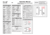
1
FRONT PANEL LAYOUT
The controller front panel comprises of Digital Readouts, LED Indicators and Push Button Keys as shown in Figure 1.1 (a) &
1.1 (b) below.
READOUTS
The Upper Readout is a 4 digit, 7-segment bright red LED display and usually displays the PV (Process Value). In Set-up
Mode, the Upper Readout displays parameter values/options.
The Lower Readout is a 4 digit, 7-segment bright green LED display and usually displays Setpoint Value or % Output Power. In
Set-up Mode, the Lower Readout displays parameter names (prompts) .
User Manual
neuro 102 Plus
Section 1
Output-1 Status Output-2 Status
Upper Readout
Lower Readout
PPI
neuro 102L Plus
OUT1 OUT2
ALM1
MODE
ALM2
Alarm-1 Indicator
Alarm-2 Indicator
Operation Mode
Indicator
ENTER Key
UP Key
DOWN Key
PAGE Key
Figure 1.1 (b) : neuro 102L Plus
Figure 1.1 (a) : neuro 102V Plus
PPI
neuro 102V Plus
OUT1 OUT2 MODE
1
2
AL
Upper Readout
Lower Readout
Operation Mode
Indicator
ENTER Key
DOWN Key
PAGE Key
Output-1 Status
Output-2 Status
Alarm-1 Indicator
Alarm-2 Indicator
UP Key

User Manual
neuro 102 Plus
2
KEYS
There are four tactile keys provided on the front panel for configuring the controller, setting-up the parameter values and
selecting Operation Modes. Refer Table 1.2 for detailed key operations.
Table 1.2
Symbol Key Function
Press to enter or exit set-up mode.
DOWN
UP
ENTER Press to store the set parameter value and to scroll to the next
parameter on the PAGE.
Press to increase the parameter value. Pressing once increases the
value by one count; keeping pressed speeds up the change.
Press to decrease the parameter value. Pressing once decreases
the value by one count; keeping pressed speeds up the change.
PAGE
Table 1.1
MODE
(Dual Colour LED :
Red & Green)
Indicates Output-2 ON/OFF status if the control output is Relay / SSR
Remains OFF if the control output is DC Linear (mA / V)
OUT2
(Red LED)
Flashes while Alarm-1 is active
1 (Red LED)
2 (Red LED) Flashes while Alarm-2 is active
Indicator Status
OUT1
(Red LED)
Indicates Output-1 ON/OFF status if the control output is Relay / SSR
Remains OFF if the control output is DC Linear (mA / V)
*AL
INDICATORS
The front panel indicators are LED’s that show the status related to control, alarm and operation mode. Refer Table 1.1 below
for details.
Flashes while Alarm-1 is active
**ALM1 (Red LED)
**ALM2 (Red LED) Flashes while Alarm-2 is active
* Applicable for Model neuro 102V Plus
** Applicable for Model neuro 102L Plus
—Remains OFF if controller is in Auto Mode with Main Control
Setpoint (SP) active
—Glows Red if controller is in Manual Mode
—Flashes Green while the Ramp/Soak profile is in progress & glows
steady Green if profile is in HOLD State
—Glows Green if Auxiliary or Remote Setpoint is Active

3
Heat or Cool Power
Uni-directional Control Bi-directional Control
Heat Power Cool Power
Figure 2.1
POWER-UP
Upon power-up, all displays and indicators are lit on for approximately 3 seconds. This is followed by the indication of the
controller model name on the Upper Readout and the firmware version on the Lower Readout, for
approximately 1 second.
MAIN DISPLAY MODE
After the Power-up display sequence, the Upper Readout starts showing the measured PV (Process Value) and the Lower
Readout displays the Setpoint Value. This is the MAIN Display Mode that shall be used most often.
% Output Power Indication
In PID control mode, the Lower Readout can be toggled using ENTER key to indicate either % output power or setpoint value
SP. The output power is indicated with the left most digit showing ‘P’, ‘H’ or ‘C’ depending upon uni-directional (Heat or Cool) or
bi-directional (Heat and Cool) control mode. Refer Figure 2.1 below.
Tune Mode Indication
The Lower Readout flashes while the controller is Tuning. Do not disturb the process or alter any parameter values
while Tuning is in progress. The “Tune” message automatically disappears upon completion of Tuning procedure.
Profile Mode Indications
While a Profile Cycle is in progress, the front panel indicator ‘PRF’ flashes or glows steadily. The steady glowing indicates that
though the profile is active, it is currently in HOLD state. Also, the Lower Readout shows the Profile Setpoint instead of the
control setpoint SP. The % Output Power (if PID Control) can be viewed by toggling the Lower Readout using ENTER key.
Note :
While Profile Cycle is in progress, the Control Setpoint SP can still be adjusted on Lower Readout. While the Lower Readout shows Profile
Setpoint, use UP/DOWN keys to adjust the control setpoint SP as described earlier.
PV Error Indications
The PV Error type is flashed on the Upper Readout. For different errors and the causes, refer Table 2.1 below.
BASIC OPERATION
Adjusting SP (Control Setpoint)
If permitted at Supervisory Level, the SP value can be directly adjusted on the Lower Readout in the MAIN Display Mode.
While the Lower Readout shows the control setpoint, step through the following sequence for adjusting the SP value :
1. Press and release UP or DOWN key once. The Lower Readout starts flashing.
2. Use UP/ DOWN keys to adjust the SP value.
3. Press and release ENTER key. The Lower Readout stops flashing and the new set value is registered and stored.
User Manual
neuro 102 Plus
Section 2

Table 2.1
PV above Max. Range
PV below Min. Range
Message Error Type Cause
Thermocouple / RTD broken
Sensor Open
Under-range
Over-range
CONTROL / ALARM STATUS UNDER PV ERROR CONDITIONS
a) The tuning, if in progress, is aborted.
b) The Profile Cycle, if in progress, enters in HOLD state.
c) Under Over-range or Under-range error condition, all the control outputs are switched off. However, under Sensor Open
error, the PID control output power is maintained at the value set for the parameter “Sensor Break Output Power” on
PAGE-12.
d) For Alarm activation, the under-range condition is treated as minimum PV, whereas the over-range and open conditions
are treated as maximum PV. Thus, Process High, positive Deviation Band and Window Band alarms activate under Over-
range/Open error. Similarly, Process Low, negative Deviation Band and Window Band alarms activate under Under-range
error.
User Manual
neuro 102 Plus
4
Auxiliary Set-point Mode Indication
(Applicable if controller is supplied with Auxiliary Set-point option)
The Controller is supplied with 2 rear panel terminals for connecting remote switch (potential-free contacts) to toggle between
Main Control Set-point (SP) & Auxiliary Control Set-point.
The “Open” & “Close” switch positions activate Main Control Set-point (SP) & Auxiliary Control Set-point, respectively.
The front panel indicator ‘MODE’ glows steady with Green color if Auxiliary Control Set-point is active.
Remote Set-point Mode Indication
(Applicable if controller is supplied with Remote Set-point option)
The Controller accepts DC Current (0/4-20 mA) or DC Voltage (0-5/10 V) as Remote Set-point Input. The parameter ‘Remote
Set-point’ on PAGE-17 must be set to ‘Enable’ for activating Remote Set-point feature. If this parameter is set to
‘Disable’ then the controller always treats Main Control Set-point (SP) as active.
The Controller also provides 2 rear panel terminals for connecting remote switch (potential-free contacts) to toggle between
Main Control Set-point (SP) & Remote Control Set-point, if ‘Enabled’ on PAGE-17.
The “Open” & “Close” switch positions activate Remote Control Set-point & Main Control Set-point (SP), respectively.
The front panel indicator ‘MODE’ glows steady with Green color if Remote Control Set-point is active.
PV Error Indications
The PV Error Type is flashed on the Upper Readout. For different Error Types and the Causes, refer Table 2.1 below.

User Manual
neuro 102 Plus
5
MANUAL MODE OPERATION
This operation mode is available only if the control action is PID and if the manual mode operation is permitted at supervisory
level. In this mode, the controller operates in Open loop mode wherein the % Output Power is manually adjusted by the
operator. This mode is often used for process start-up to make sure that the process equilibrium is achieved before the control
is transferred for subsequent automatic (closed loop) control. The controller ensures a bumpless Auto / Manual transfer.
The manual mode can be activated or de-activated using ENTER key. While in manual mode, the Upper Readout shows PV
while the Lower Readout shows % Power that can be adjusted using UP/DOWN keys.
Follow the steps below to enter (Activate) into Manual Mode and to revert to (De-activate) Automatic Mode.
1. Hold ENTER key pressed for approximately 2 seconds until front panel indicator MODE glows steady with Red color.
2. Release Enter key. The controller is now placed in Manual mode. The Upper Readout displays the PV and the Lower
Readout displays the %Output Power.
3. Adjust the Output Power using the UP and DOWN keys. The Output Power is adjustable between the set Power Low and
Power High limits.
To de-activate the Manual mode; Hold the ENTER key pressed for approximately 2 seconds until the front panel indicator
MODE turns off. The controller now enters into Auto control mode with the first power same as that was adjusted last while in
Manual mode.
Notes:
1. The Controller can not be placed in Manual mode while a Profile Cycle is in progress. If the controller is in manual mode and if profile start
command is issued, the controller reverts to Auto Mode and initiates profile.
2. The Manual mode Activation / De-activation is suppressed while the Tuning is in progress. However, the Tuning procedure can be
activated regardless of whether the controller is in Auto or Manual control mode.
3. While the Controller is in Manual Mode, Standby Mode (explained later in this section) can not be entered and vice-a-versa.
4. If the power fails while the Manual Control Mode is active; upon resumption of power the controller continues to remain in Manual control
mode with the last user set power.
STANDBY MODE
This mode, allows the operator to put the controller in ‘indication-only’ mode wherein all the output control signals as well as
Alarm Relays are forced OFF. This may be desired prior to the start of a new process batch.
If enabled at supervisory level, the standby mode can be activated or de-activated by setting the parameter ‘Standby’ to Yes or
No respectively. The standby parameter is available on Operator PAGE-0.
Notes:
1. The Standby and Tuning modes are mutually exclusive. If Standby mode is activated while the controller is tuning, the controller aborts
tuning operation and enters Standby mode.
2. If the Power Supply to the controller is switched-off or a Power-failure occurs while the controller is operating in Standby mode; upon
resumption of power, the controller continues to operate in Standby mode.
OPERATOR PAGE AND PARAMETERS
The controller provides a separate page that contains parameters that require frequent settings by the operator. The page is
called Operator Page and the parameters are called Operator Parameters. The availability of operator parameters is
controlled at supervisory level and the parameter settings is not locked by the Master Lock.

User Manual
neuro 102 Plus
5
Accessing Operator Page & Adjusting Parameters
Step through the following sequence to open the operator page and to adjust the operator parameter values.
1. Press and release PAGE key. The Lower Readout shows (PAGE) and Upper Readout shows (0).
2. Press ENTER key. The Lower Readout shows prompt for the first available operator parameter and the Upper Readout
shows value for the parameter.
3. Use UP / DOWN keys to adjust the value and then press ENTER key to store the set value and scroll to next parameter.
The controller automatically reverts to MAIN Display Mode upon scrolling through the last operator parameter. Alternatively,
use PAGE key to return to MAIN Display Mode.
The operator parameters are described in Table 2.2. Note that the parameters presented on operator page depend upon the
functions selected/enabled and supervisory level permissions.
ACTIVATE / DE-ACTIVATE STANDBY MODE
This parameter is available and applicable only if Standby mode is
enabled at supervisory level. Set the parameter value to ‘Yes’ or
‘No’ for entering and exiting the Standby mode, respectively.
Setpoint Low Limit
to Setpoint High Limit
(Default : -1999)
This is the Main Setpoint value that the controller respects for the
control purpose while it is not running a profile or not in standby /
tuning mode.
CONTROL SETPOINT
No
Yes
(Default : No)
Parameter Description Settings
(Default Value)
ALARM-2 WINDOW BAND
Same as that described for Alarm-1 above but applied to Alarm-2.
ALARM-2 DEVIATION BAND
ALARM-2 SETPOINT
ALARM-1 WINDOW BAND
The Alarm setpoint for Alarm-1 if the Alarm Type is Window Band.
ALARM-1 DEVIATION BAND
The Alarm setpoint for Alarm-1 if the Alarm Type is Deviation Band.
ALARM-1 SETPOINT
The Alarm setpoint for Alarm-1 if the Alarm Type is set to Process
High or Process Low.
Same as that for Alarm-1 above but
applied to Alarm-2.
Table 2.2
For DC mA/mV/V : 3 to 9999 counts
For Thermocouples/RTD :
3 to 999 or 0.3 to 999.9
(Default : 0)
Min. to Max. Range
specified for the
selected Input Type
(Default : Min or Max Range)
For DC mA/mV/V :
-1999 to 9999 counts
For Thermocouples/RTD :
-999 to 999 or -1.999 to 999.9
(Default : 0)

User Manual
neuro 102 Plus
7
AUXILIARY CONTROL SETPOINT
(Available only if the Controller is supplied with Auxiliary Set-point
option)
The alternate control set-point that the controller respects for
control purpose when selected through remote input terminals.
Setpoint Low Limit
to Setpoint High Limit
(Default : -1999)
Parameter Description Settings
(Default Value)

User Manual
neuro 102 Plus
8
The various parameters are arranged in different groups, called PAGES, depending upon the functions they represent. Each
group is assigned a unique numeric value, called PAGE NUMBER, for its access.
The parameters are always presented in a fixed format: The Lower Readout displays the parameter prompt (Identification
Name) and the Upper Readout displays the set value. The parameters appear in the same sequence as listed in their
respective sections.
SET-UP MODE
The Set-up Mode allows the user to view and modify the parameter values. Follow the steps below for setting the parameter
values:
1. Press and release PAGE key. The Lower Readout shows PAGE and the Upper Readout shows page number 0. Refer
Figure 3.1.
2. Use UP / DOWN keys to set the desired PAGE NUMBER.
3. Press and release ENTER key. The Lower Readout shows the prompt for the first parameter listed in the set PAGE
NUMBER and the Upper Readout shows its current value. If the entered PAGE NUMBER is invalid (contains no
parameter list or any associated function), the controller reverts to the MAIN Display Mode.
4. Press and release the ENTER key until the prompt for the required parameter appears on the Lower Readout. (The last
parameter in the list rolls back to the first parameter).
5. Use UP / DOWN keys to adjust the parameter value. (The display flashes if UP key is pressed after reaching the maximum
value or DOWN key is pressed after reaching the minimum value).
6. Press and release the ENTER key. The new value gets stored in the controller’s non-volatile memory and the next
parameter in the list is displayed.
The Figure 3.1 illustrates the example of altering the value for the parameter ‘Control Action’ from On-Off to PID.
SET-UP MODE : ACCESS AND OPERATION
Figure 3.1
Notes
1. Each page contains a fixed list of parameters that are presented in a pre-determined sequence. Note however that availability of a few
parameters, called Conditional Parameters, depend upon the settings for some other parameters. For example, the parameter ‘Control
Hysteresis’ for Output-1 is available only if, the set value for the parameter ‘Control Action’ is ‘On-Off’.
2. To exit the set-up mode and return to the MAIN Display Mode, press and release PAGE key.
3. If no key is pressed for approximately 30 seconds, the set-up mode times out and reverts to the MAIN Display Mode.
Section 3
Use UP/DOWN
keys to change
the value
Press ENTER
key to store the value &
move to next parameter
First Parameter
on Page-12
New Parameter
value
Next Parameter
on Page-12
or
or
Main Display
Mode
Default Page Page Number
Press PAGE
key to enter
Set-up Mode
Use UP/DOWN
key to set the
Page Number
Press ENTER
key to open
the Page

User Manual
neuro 102 Plus
9
MASTER LOCKING
The controller facilitates locking all the PAGES (except Operator PAGE) by applying Master Lock Code. Under Locking, the
parameters are available for view only and cannot be adjusted. The Master Lock, however does not lock the operator
parameters. This feature allows protecting the rather less frequently used parameters against any inadvertent changes while
making the frequently used operator parameters still available for any editing.
For enabling / disabling the Lock, step through the following sequence:
Locking
1. Press and release PAGE key while the controller is in the MAIN Display Mode. The Lower Readout shows PAGE and the
Upper Readout shows 0.
2. Use UP / DOWN keys to set the Page Number to 123 on the Upper Readout.
3. Press and release ENTER key. The controller returns to the MAIN Display Mode with the Lock enabled.
The Figure 3.2 below illustrates the Locking procedure.
Figure 3.2
or
MAIN Display
Mode
Default Page Locking Code MAIN Display
Mode
Press PAGE
key to enter
Set-up Mode
Use UP/DOWN
key to set the
‘Locking Code’
Press ENTER key
to Lock & Return to
Main Mode
UnLocking
Repeat the Locking procedure twice for unlocking.

User Manual
neuro 102 Plus
10
Refer Table 4.1 for the parameter descriptions and settings.
CONTROL PARAMETERS : PAGE-10
Table 4.1
0 to 600 Seconds
(Default : 16 sec.)
0 to 3600 Seconds
(Default : 100 sec.)
Parameter Description Settings
(Default Value)
PROPORTIONAL BAND
(Available for PID Control only)
Sets proportional gain (% power per unit error). Defined in same
units and resolution as that for PV.
INTEGRAL TIME
(Available for PID Control only)
Sets integral time constant in seconds. Setting the value to 0, cuts-
off integral action.
DERIVATIVE TIME
(Available for PID Control only)
Sets derivative time constant in seconds. Setting the value to 0,
cuts-off derivative action.
0.5 to 100.0 Seconds
(in steps of 0.5 secs.)
(Default : 10.0 sec.)
CYCLE TIME
(Available for PID Control only)
Sets the total ‘On + Off’ time in seconds for time modulating power
output through OP1 Relay / SSR.
0.1 to 10.0
(Default : 1.0)
RELATIVE COOL GAIN
(Available for PID Control with bi-directional, that is, Heat-
Cool mode)
Sets the ratio of cooling power to the heating power.
COOL CYCLE TIME
(Available for PID Control with bi-directional, that is, Heat-
Cool mode)
Sets the On + Off cycle time in seconds for time modulating power
output through OP2 Relay / SSR.
0.5 to 100.0 Seconds
(in steps of 0.5 secs.)
(Default : 10.0 sec.)
HYSTERESIS
(Available for On-Off or Pulsed On-Off Control only)
Sets differential (dead) band between On-Off switching for OP1.
Defined in same units and resolution as that for PV.
PULSE TIME
(Available for Pulsed On-Off Control only)
Sets the total ‘On + Off’ pulse time in seconds for OP1 Relay / SSR
output.
Pulse ON Time
to 120.0 Seconds
(Default : 2.0 sec.)
Section 4
For DC mA/mV/V : 1 to 9999 counts
For Thermocouples/RTD :
1 to 999 or 0.1 to 999.9
(Default : 500)
For DC mA/mV/V : 1 to 9999 counts
For Thermocouples/RTD :
1 to 999 or 0.1 to 999.9
(Default : 20)

User Manual
neuro 102 Plus
11
Parameter Description Settings
(Default Value)
COOL PULSE TIME
(Available for Pulsed On-Off Control with bi-directional
mode)
Sets the total ‘On + Off’ pulse time in seconds for OP2 Relay / SSR
output.
Cool ON Time
to 120.0 Seconds
(Default : 2.0)
0.1 to Value set for
Cool Pulse Time
(Default : 1.0)
HEAT POWER LOW
(Available for PID Control only)
Sets the minimum % output power limit for OP1.
0 to Heat Power High
(Default : 0)
HEAT POWER HIGH
(Available for PID Control only)
Sets the maximum % output power limit for OP1 .
Heat Power Low to 100
(Default : 100)
COOL HYSTERESIS
(Available for On-Off or Pulsed On-Off Control with bi-
directional mode)
Sets differential (dead) band between On-Off switching for OP2.
Defined in same units and resolution as that for PV.
COOL PULSE-ON TIME
(Available for Pulsed On-Off Control with bi-directional
mode)
Sets the ON pulse time in seconds for OP2 Relay / SSR output.
COOL POWER LOW
(Available for PID Control with bi-directional, that is, Heat-
Cool mode)
Sets the minimum % output power limit for OP2.
0 to Cool Power High
(Default : 0)
0.1 to Value set
for Pulse Time
(Default : 1.0)
PULSE-ON TIME
(Available for Pulsed On-Off Control only)
Sets the ON pulse time in seconds for OP1 Relay / SSR output.
COOL POWER HIGH
(Available for PID Control with bi-directional, that is, Heat-
Cool mode)
Sets the maximum % output power limit for OP2.
Cool Power Low to 100
(Default : 100)
For DC mA/mV/V : 1 to 9999 counts
For Thermocouples/RTD :
1 to 999 or 0.1 to 999.9
(Default : 20)

User Manual
neuro 102 Plus
12
Refer Table 5.1 for parameter description & settings.
ALARM AND RETRANSMISSION (RECORDER) PARAMETERS : PAGE 11
Table 5.1
Parameter Description Settings
(Default Value)
ALARM-1 TYPE
Selects the Alarm-1 activation type. Selecting ‘None’ disables the
alarm and suppresses all the related parameters for Alarm-1.
None
Process Low
Process High
Deviation Band
Window Band
(Default : None)
ALARM-1 SETPOINT
(Available for Process High or Process Low Alarm-1 Type)
Sets Alarm limit independent of control setpoint for Alarm-1
Activation. Defined in same units and resolution as that for PV.
ALARM-1 DEVIATION BAND
(Available for Deviation Band Alarm-1 Type)
Sets positive or negative deviation (offset) limit from control
setpoint for High or Low Alarm-1 activation, respectively. Defined
in same units and resolution as that for PV.
Min. to Max. Range
specified for the
selected Input Type
(Default : Min or Max Range)
ALARM-1 WINDOW BAND
(Available for Window Band Alarm-1 Type)
Sets symmetrical positive and negative deviation (offset) limits
from control setpoint for both High and Low Alarm-1 activation.
Defined in same units and resolution as that for PV.
ALARM-1 HYSTERESIS
Sets differential (dead) band between Alarm-1 switching ON and
OFF states. Defined in same units and resolution as that for PV.
ALARM-1 INHIBIT
Setting to ‘Yes’ suppresses Alarm-1 activation upon power-up or
process start-up. (Default : No)
No
Yes
Section 5
ALARM-2 TYPE
Selects the Alarm-2 activation type. Selecting ‘None’ disables the
alarm and suppresses all the related parameters for Alarm-2.
None
Process Low
Process High
Deviation Band
Window Band
(Default : None)
For DC mA/mV/V : 1 to 9999 counts
For Thermocouples/RTD :
1 to 999 or 0.1 to 999.9
(Default : 2)
For DC mA/mV/V : 3 to 9999 counts
For Thermocouples/RTD :
3 to 999 or 0.3 to 999.9
(Default : 5)
For DC mA/mV/V :
-1999 to 9999 counts
For Thermocouples/RTD :
-999 to 999 or -1.999 to 999.9
(Default : 5)

User Manual
neuro 102 Plus
13
Parameter Description Settings
(Default Value)
ALARM-2 SETPOINT
ALARM-2 DEVIATION BAND
Min. to Max. Range
specified for the
selected Input Type
(Default : Min or Max Range)
ALARM-2 WINDOW BAND
ALARM-2 HYSTERESIS
ALARM-2 INHIBIT
Set to Yes to suppress Alarm-2 activation upon power-up or
process start-up. (Default : No)
No
Yes
(Available for Window Band Alarm-2 Type)
Sets symmetrical positive and negative deviation (offset) limits
from control setpoint for both High and Low Alarm-2 activation.
Defined in same units and resolution as that for PV.
(Available for Deviation Band Alarm-2 Type)
Sets positive or negative deviation (offset) limit from control
setpoint for High or Low Alarm-2 activation, respectively. Defined
in same units and resolution as that for PV.
(Available for Process High or Process Low Alarm-2 Type)
Sets Alarm limit independent of control setpoint for Alarm-2
Activation. Defined in same units and resolution as that for PV.
Sets differential (dead) band between Alarm-2 switching ON and
OFF states. Defined in same units and resolution as that for PV.
Process Value
Setpoint
(Default : Process Value)
(Available if OP3 function is recorder)
Selects either Process Value (PV) or Control Setpoint (SP) for
retransmission (recording).
PV/SP SELECTION FOR RETRANSMISSION
RECORDER (RETRANSMISSION) LOW
(Available if OP3 function is recorder)
Sets the minimum value (PV or SP) that shall correspond to the
minimum recorder output signal level (0 mA or 4 mA or 0 V). (Default : -199)
Min. to Max. Range
Specified for the
Selected Input Type
(Default : 1376)
Min. to Max. Range
Specified for the
Selected Input Type
RECORDER (RETRANSMISSION) HIGH
(Available if OP3 function is recorder)
Sets the maximum value (PV or SP) that shall correspond to the
maximum recorder output signal level (20 mA or 10 V or 5 V).
For DC mA/mV/V : 1 to 9999 counts
For Thermocouples/RTD :
1 to 999 or 0.1 to 999.9
(Default : 2)
For DC mA/mV/V : 3 to 9999 counts
For Thermocouples/RTD :
3 to 999 or 0.3 to 999.9
(Default : 5)
For DC mA/mV/V :
-1999 to 9999 counts
For Thermocouples/RTD :
-999 to 999 or -1.999 to 999.9
(Default : 5)

14
User Manual
neuro 102 Plus
SENSOR BREAK OUTPUT POWER
(Available for PID control only)
In case of Thermocouple / RTD broken or disconnected, the
controller outputs this power value under open loop condition.
INPUT/OUTPUT CONFIGURATION PARAMETERS : PAGE-12
Refer Table 6.1 for parameter description & settings.
Table 6.1
Parameter Description Settings
(Default Value)
CONTROL ACTION
Select appropriate Control Algorithm suited for process
requirement.
CONTROL LOGIC
Select Reverse (heat logic) or Direct (cool logic).
PV UNITS
(Available for Thermocouple / RTD Inputs)
Selects temperature measurement units in °C or °F.
INPUT TYPE
Select Input type in accordance with the type of Thermocouple or
RTD or Sensor / Transducer Output (mA/mV/V) connected for
process value measurement.
Refer Table 6.2
(Default : Type K)
(Default : C)°
°F
°C
(Default : Reverse)
Reverse
Direct
(Default : PID)
On-Off
PID
Pulse
Section 6
SETPOINT LOW LIMIT
Set minimum permissible control setpoint value.
(Default : -199)
Min. Range to
Setpoint High for the
selected Input Type
SETPOINT HIGH LIMIT
Set maximum permissible control setpoint value.
Setpoint Low to
Max. Range for the
selected Input Type
(Default : 1376)
0 to 100
(Default : 0)
Input Type Settings Default
0 to 20 mA 0.00 to Signal High 0.00
4 to 20 mA
0 to 80 mV
Reserved
0 to 1.25 V
0 to 5 V
0 to 10 V
1 to 5 V
4.00 to Signal High
0.00 to Signal High
0.0 to Signal High
0.000 to Signal High
0.000 to Signal High
0.00 to Signal High
1.000 to Signal High
4.00
0.00
0.0
0.000
0.000
0.00
1.000
SIGNAL LOW
(Available for DC linear mV/V/mA Inputs only)
The transmitter output signal value corresponding to PV RANGE
LOW parameter value. Refer Appendix-A : DC Linear Signal
Interface for details.

User Manual
neuro 102 Plus
15
PV RESOLUTION
(Available for DC linear mV/V/mA & RTD Inputs only)
Set the process value indication resolution (decimal point). All the
resolution based parameters (Control Setpoint, Hysteresis, Alarm
Setpoints etc.) then follow this resolution setting.
PV RANGE LOW
(Available for DC Linear Inputs)
Set process value corresponding to SIGNAL LOW parameter
value.
PV RANGE HIGH
(Available for DC Linear Inputs)
Set process value corresponding to SIGNAL HIGH parameter
value.
Parameter Description Settings
(Default Value)
OFFSET FOR PV
This value is algebraically added to the measured PV to derive the
final PV that is displayed and compared for alarm / control.
Final PV = Measured PV + Offset
0.5 to 60.0 Seconds
(in steps of 0.5 Seconds)
(Default : 2.0 sec.)
DIGITAL FILTER TIME CONSTANT
Set the time constant, in seconds, for the low-pass digital filter
applied to the measured PV. The filter helps smoothing/averaging
the signal input and removing the undesired noise.
SIGNAL HIGH
(Available for DC linear mV/V/mA Inputs only)
The transmitter output signal value corresponding to PV RANGE
HIGH parameter value. Refer Appendix-A : DC Linear Signal
Interface for details.
Input Type Settings Default
0 to 20 mA
4 to 20 mA
0 to 80 mV
Reserved
0 to 1.25 V
0 to 5 V
0 to 10 V
1 to 5 V
Signal Low to 20.00 20.00
20.00
80.00
80.00
1.250
5.000
10.00
5.000
Signal Low to 20.00
Signal Low to 80.00
Signal Low to 80.00
Signal Low to 1.250
Signal Low to 5.000
Signal Low to 10.00
Signal Low to 5.000
Refer Table 6.2
(Default : 1)
-1999 to 9999
(Default : 0)
-1999 Low to 9999
(Default : 1000)
For DC mA/mV/V : 1 to 9999 counts
For Thermocouples/RTD :
1 to 999 or 0.1 to 999.9
(Default : 0)

User Manual
neuro 102 Plus
16
Table 6.2
Resolution
Option What it means Range (Min. to Max.)
Type J Thermocouple
Type K Thermocouple
Type T Thermocouple
0 to +960°C / +32 to +1760°F
-200 to +1376°C / -328 to +2508°F
-200 to +385°C / -328 to +725°F
Type R Thermocouple
0 to +1770°C / +32 to +3218°F
Fixed
1°C / 1°F
0 to 20mA DC current
4 to 20mA DC current
0 to 80mV DC voltage
Reserved
0 to 1.25V DC voltage
0 to 5.0V DC voltage
0 to 10.0V DC voltage
1 to 5.0V DC voltage
3-wire, RTD Pt100
-1999 to +9999 units
-199 to +600°C / -328 to +1112°F
-199.9 to 600.0°C / -199.9 to 999.9°F
or
User settable
1°C / 1°F
or
0.1°C / 0.1°F
User settable
1 / 0.1 / 0.01/
0.001 units
Type N Thermocouple
Type B Thermocouple
Type S Thermocouple
0 to +1300°C / +32 to +2372°F
0 to +1825°C / +32 to +3092°F
0 to +1765°C / +32 to +3209°F
Reserved for customer specific Thermocouple type not listed
above. The type shall be specified in accordance with the ordered
(optional on request) Thermocouple type.

User Manual
neuro 102 Plus
17
SUPERVISORY PARAMETERS : PAGE-13
Refer Table 7.1 for parameter description & settings.
Table 7.1
Settings
(Default Value)
SELF-TUNE COMMAND
(Available for PID control only)
Set to ‘Yes’ to initiate a new tuning cycle or set to ‘No’ to abort a
tuning operation in progress.
Parameter Description
OVERSHOOT INHIBIT
(Available for PID control only)
Enabling this feature controls the rate of PV rise or fall upon
process start-up in order to reach the control setpoint with as
minimum overshoot/undershoot as possible.
1.0 to 2.0
(Default : 1.0)
OVERSHOOT INHIBIT FACTOR
(Available for PID control with Overshoot Inhibit enabled)
This parameter adjusts the effectiveness of the Overshoot Inhibit
feature. Increase the value if the overshoot is curbed but the PV
takes longer to reach the SP. Decreases the value if the overshoot
persists.
(Default : Disable)
Disable
Enable
(Default : No)
No
Yes
MANUAL MODE
Supervisory permission for Auto/Manual mode selection. Set to
‘Enable’ for permission.
SP ADJUSTMENT ON OPERATOR PAGE
Supervisory permission for control setpoint editing on Operator
Page. Set to ‘Enable’ for permission.
SP ADJUSTMENT ON LOWER READOUT
Supervisory permission for control setpoint editing on Lower
Readout. Set to ‘Enable’ for permission.
ALARM SP ADJUSTMENT
ON OPERATOR PAGE
Supervisory permission for Alarm setpoint adjustments on
Operator Page. Set to ‘Enable’ for permission.
STANDBY MODE
Supervisory control over availability of Standby (entry / exit)
command on Operator Page. ‘Enable’ for availability.
(Default : Enable)
Disable
Enable
(Default : Enable)
Disable
Enable
(Default : Disable)
Disable
Enable
(Default : Disable)
Disable
Enable
(Default : Disable)
Disable
Enable
Section 7

User Manual
neuro 102 Plus
18
Settings
(Default Value)
Parameter Description
PROFILE ABORT COMMAND
ON PAGE-1
Supervisory control over availability of Profile Abort command on
Page-1. ‘Enable’ for availability. (Default : Disable)
Disable
Enable
BAUD RATE
Communication speed in ‘Bits per Second’. Set the value to match
with the host baud rate.
COMMUNICATION PARITY
One of the communication error trapping features. Select the data
packet parity as implemented by the host protocol.
CONTROLLER ID NUMBER
Unique numeric code assigned to the controller for identification
by the host. Set the value as required by the host.
COMMUNICATION WRITE ENABLE
Setting to ‘No’ disallows the host to set or modify any parameter
value. The host, however, can read the values.
1 to 127
(Default : 1)
(Default : No)
No
Yes
(Default : Even)
None
Even
Odd
The Following Serial Communication Parameters are not available if the Controller is ordered with
Auxiliary Setpoint Option.
(Default : 9.6)
4800
9600
19200
38400
57600
2400
/