UPI - 5D
AL-1
AL-2
ACK
Alarm 1 Indicator
Alarm 2 Indicator
ENTER key
UP Key
PAGE Key
DOWN Key
Readout
Front Panel
Function
Symbol Key
DOWN
UP
PAGE Press to enter / exit Set-up mode.
Press to increase the parameter value. Pressing
once increases the value by one count; holding the
key pressed speeds up the change.
Press to decrease the parameter value. Pressing
once decreases the value by one count; holding the
key pressed speeds up the change.
ENTER
If Readout is showing Parameter Name in the setup
mode then upon pressing this key the Readout
shows the value for the parameter.
If Readout is showing Parameter Value in the setup
mode then upon pressing this key the set parameter
value is stored and the Readout shows the next
Parameter Name.
Note : While in Main mode, this key can be used to
acknowledge any pending Alarm(s) to de-activate
alarm relay(s).
ACK
Keys Operation
PV above Max. Range
PV below Min. Range
Message Error Type Cause
Thermocouple / RTD brokenSensor Open
Under-range
Over-range
PV Error Indications
Universal Process Indicator
with Enhanced Features
UPI-5D
Parameters Settings
(Default Value)
OPERATOR PARAMETERS : PAGE 0
Maximum PV View Only
(Default : NA)
Minimum PV View Only
(Default : NA)
Reset Command
(Default : No)
No
Yes
Reset Password 0 to 250
(Default : 0)
Alarm-1 Setpoint
Alarm-2 Setpoint
Min. to Max Range
specified for the
selected Input Type
(Default : Min. or Max Range)
Min. to Max Range
specified for the
selected Input Type
(Default : Min. or Max Range)
Parameters Settings
(Default Value)
RETRANSMISSION PARAMETERS : PAGE 11
Retransmission
(recorder)
Output Type
(Default : 0 to 20 mA)
0 to 20 mA
4 to 20 mA
0 to 5 Volts
0 to 10 Volts
Retransmission
(recorder) Low
Min. to Max. Range
specified for the
selected Input Type
(Default : -200)
Retransmission
(recorder) High
Min. to Max. Range
specified for the
selected Input Type
(Default : 1376)
None
Process Low
Process High
(Default : None)
Parameters Settings
(Default Value)
ALARM PARAMETERS : PAGE 10
Alarm-1 Type
Alarm-1 Setpoint Min. to Max Range
specified for the
selected Input Type
(Default : Min. or Max Range)
Alarm-1 Hysteresis 1 to 999 or
0.1 to 999.9
(Default : 2.0)
Alarm-1 Inhibit
(Default : No)
No
Yes
Alarm-1 Logic
(Default : Normal)
Reverse
Normal
Alarm-1 Latch
(Default : No)
No
Yes
Alarm-2 Setpoint Min. to Max Range
specified for the
selected Input Type
(Default : Min. or Max Range)
Alarm-2 Hysteresis 1 to 999 or
0.1 to 999.9
(Default : 2.0)
Alarm-2 Inhibit
(Default : No)
No
Yes
Alarm-2 Logic
(Default : Normal)
Reverse
Normal
Alarm-2 Latch
(Default : No)
No
Yes
Alarm-2 Type None
Process Low
Process High
(Default : None)
Parameters Settings
(Default Value)
USER LINEARISATION PARAMETERS : PAGE-33
User Linearization
Setting Code 0 to 9999
(Default : 0)
User Linearization
(Default : No)
No
Yes
Total Break Points 2 to 32
(Default : 2)
Break Point Number 1 to 32
(Default : 1)
Actual Value For
Break Point (X Co-ord) -1999 to 9999
(Default : Undefined)
Derived Value For
Break Point (Y Co-ord) -1999 to 9999
(Default : Undefined)
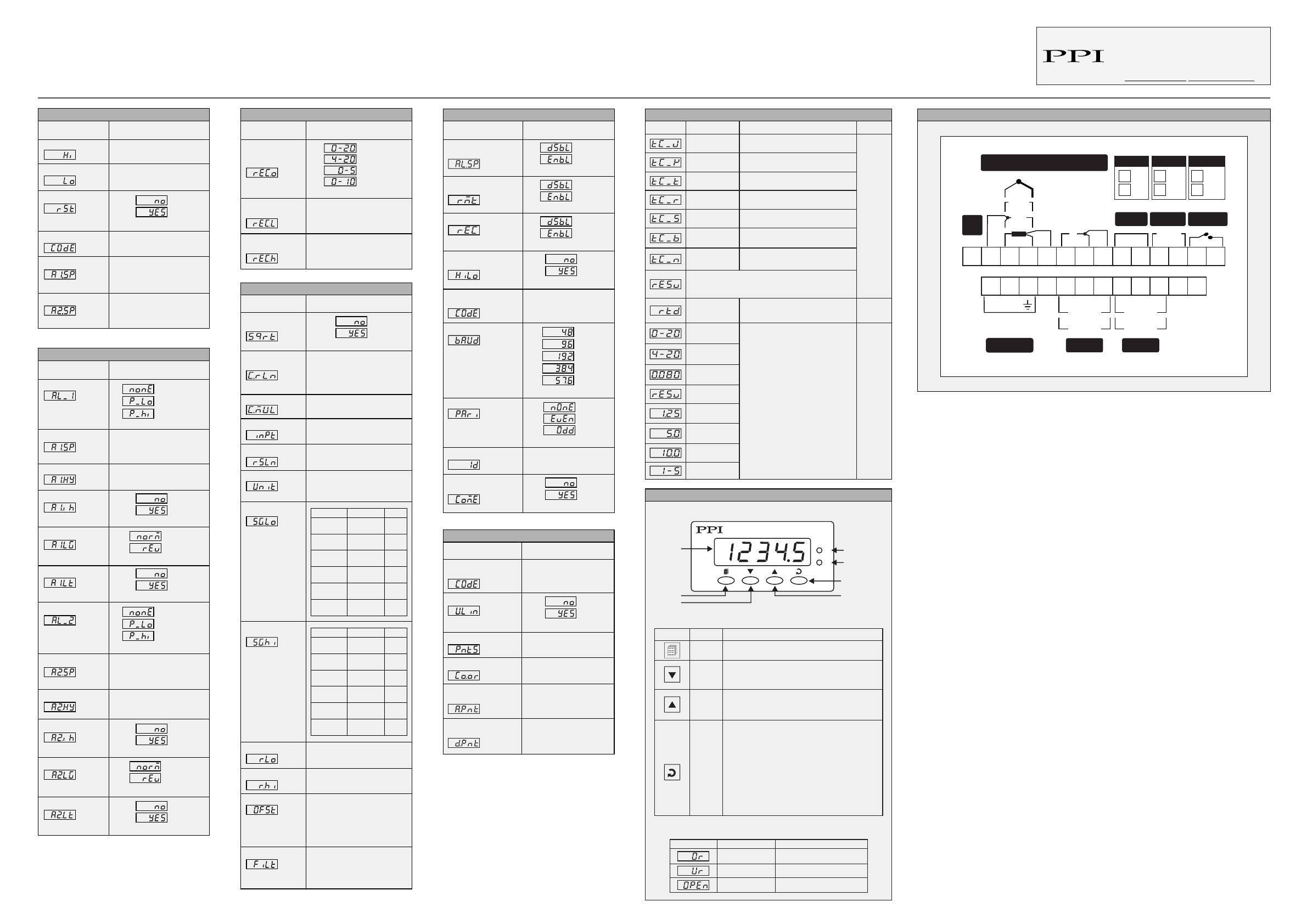
FRONT PANEL LAYOUT
Operation Manual
This brief manual is primarily meant for quick reference to wiring
connections and parameter searching. For more details on
operation and application; please log on to www.ppiindia.net
ELECTRICAL CONNECTIONS
-19999 to 30000
(Default : 0.0)
-19999 to 30000
(Default : 100.0)
For DC Lin. Volts/Current
-19999 to 30000 Counts
For Thermocouple/RTD
-1999 to 3000 or
-1999.9 to 3000.0
(Default : 0)
0.0 to 60.0 Seconds
(Default : 2.0 sec.)
Parameters Settings
(Default Value)
INPUT CONFIGURATION PARAMETERS : PAGE-12
Refer Table 1
(Default : Type K)
Refer Table 1
(Default : 1°C)
°C
°F
(Default : ºC)
1
0.1
0.01
0.001
(Default : 1)
1 to 9999
(Default : 0)
DC Signal Low
DC Signal High
DC Range Low
DC Range High
Offset
Digital Filter
Input Type
Resolution
Units
Square Root
Selection
Const Multiplier
Resolution
Const Multiplier
(Default : No)
No
Yes
Parameters Settings
(Default Value)
Alarm SP Adjustment
On Operator Page
(Default : Disable)
Disable
Enable
Process Value
High-low Monitoring
(Default : No)
No
Yes
Password for Resetting
PV High-low 0 to 250
(Default : 0)
SUPERVISORY PARAMETERS : PAGE-13
Baud Rate
(Default : 9.6)
4800
9600
19200
38400
57600
Parity
(Default : Even)
None
Odd
Even
Serial ID Number
Serial Write
Permission No
Yes
(Default : No)
1 to 127
(Default : 1)
Recorder
Remote Alarm
Acknowledge Switch
(Default : Disable)
Disable
Enable
(Default : Disable)
Disable
Enable
-19999 to 30000 units
1
0.1
0.01
0.001
units
0 to 20mA
DC current
4 to 20mA
DC current
0 to 80mV
DC voltage
Reserve
0 to 1.25V
DC voltage
0 to 5.0V
DC voltage
0 to 10.0V
DC voltage
1 to 5.0V
DC voltage
3-wire,
RTD Pt100
1 °C/°F
or
0.1 °C/°F
-199.9 to +600.0°C / -328.0 to +1112.0°F
Resolution
Option What it means Range (Min. to Max.)
Reserved for customer specific Thermocouple type not
listed above. The type shall be specified in accordance with
the ordered (optional on request) Thermocouple type.
0.0 to +1314.0°C / +32.0 to +2397.0°F
0.0 to +1826.0°C / +32.0 to +3218.0°F
0.0 to +1768.0°C / +32.0 to +3214.0°F
0.0 to +1771.0°C / +32.0 to +3219.0°F
-200.0 to +387.0°C / -328.0 to +728.0°F
-200.0 to +1376.0°C / -328.0 to +2508.0°F
0.0 to +960.0°C / +32.0 to +1760.0°F
Type J
Thermocouple
1 °C/°F
or
0.1 °C/°F
Type K
Thermocouple
Type T
Thermocouple
Type R
Thermocouple
Type S
Thermocouple
Type B
Thermocouple
Type N
Thermocouple
TABLE 1
Input Type Settings Default
0 to 20 mA 0.00 to
Signal High 0.00
4 to 20 mA 4.00 to
Signal High 4.00
0 to 5 V 0.000 to
Signal High 0.000
0 to 10 V 0.00 to
Signal High 0.00
1 to 5 V 1.000 to
Signal High 1.000
0 to 80 mV 0.00 to
Signal High 0.00
Input Type Settings Default
0 to 20 mA
4 to 20 mA
0 to 5 V
0 to 10 V
1 to 5 V
Signal Low
to 20.00
Signal Low
to 20.00
Signal Low
to 5.000
Signal Low
to 10.00
Signal Low
to 5.000
20.00
20.00
5.000
10.00
5.000
0 to 80 mV
Signal Low
to 80.00 80.00
Lbl. Ref. : B127-V2
UPI-5D
B+ B-
mA
mV
TC
RTD
+ + +
–
–
–
mA/V
+
–
–
+
V
PV Input
RS485 Retrans
24V
Exc
O/P
1 2 3456 7 8 9 10 11 12 13 14
19 20 21 22 23 24 25 26
NC C NO
RELAY
+
–
SSR
ALM 1
15 16 17 18
85~265
VAC
Supply
N
LNC C NO
RELAY
+
–
SSR
ALM 2
ALM ACK
mA
V
RLY
SSR
RLY
SSR
Retrans ALM 1 ALM 2
(Setting the Value
to 0.0 disables the filter)
101, Diamond Industrial Estate, Navghar,
Vasai Road (E), Dist. Palghar - 401 210.
Sales : 8208199048 / 8208141446
Support : 07498799226 / 08767395333
Jan 2022