Page is loading ...


CONTENTS
User Manual
neuro 100
1. FRONT PANEL LAYOUT 1
2. BASIC OPERATION 3
3. SET-UP MODE ACCESS AND OPERATION 5
4. ALARM PARAMETERS 7
5. RETRANSMISSION PARAMETERS 9
6. INPUT CONFIGURATION 10
7. SUPERVISORY PARAMETERS 14
8. USER LINEARISATION PARAMETERS 16
9. HARDWARE ASSEMBLY & CONFIGURATIONS 17
10. MECHANICAL INSTALLATION 23
11. ELECTRICAL CONNECTIONS 25
For Size 48X48
For Size 96X96
1. FRONT PANEL LAYOUT 30
2. HARDWARE ASSEMBLY & CONFIGURATION 32
3. 36ELECTRICAL CONNECTIONS

1
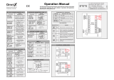
The indicator front panel comprises of digital readouts, LED indicators and membrane keys as shown in Figure 1.1 below.
FRONT PANEL LAYOUT
Figure 1.1
READOUTS
The Upper Readout is a 4 digit, 7-segment bright red LED display and usually displays the PV (Process Value).In Set-up
Mode, the Upper Readout displays parameter values/options.
The Lower Readout is a 4 digit, 7-segment bright green LED display and usually displays Process Value Units. In case of any
active Alarm(s), the Lower Readout flashes Alarm Status information. In Set-up Mode, the Lower Readout displays the names
(identifier tags) for the parameters.
INDICATORS
The front panel comprises 2 LED indicators that show Alarm status. Refer Table 1.1 below for details.
Flashes while Alarm-1 is active.
AL1
AL2 Flashes while Alarm-2 is active.
LED Status
Table 1.1
KEYS
There are four tactile keys provided on the front panel for configuring the indicator, setting-up the parameter values. Refer
Table 1.2 below.
User Manual
neuro 100
Section 1
DOWN Key
PAGE Key
Alarm-1 Status
neuro 100
PPI
Upper Readout
Lower Readout
ENTER Key
UP Key
Alarm-2 Status
AL1 AL2

2
User Manual
neuro 100
Table 1.2
Symbol Key Function
Press to enter or exit set-up mode.
PAGE
DOWN
UP
ENTER Press to store the set parameter value and to scroll to the next
parameter on the PAGE.
Press to increase the parameter value. Pressing once increases the
value by one count; keeping pressed speeds up the change.
Press to decrease the parameter value. Pressing once decreases
the value by one count; keeping pressed speeds up the change.

3
POWER-UP
Upon power-up, all displays and indicators are lit on for approximately 3 seconds. This is followed by the indication of the
indicator model name on the Upper Readout and the firmware version o n t h e L ower Readout, for
approximately 1 second.
MAIN DISPLAY MODE
After the Power-up display sequence, the Upper Readout starts showing the measured PV (Process Value) and the Lower
Readout displays the user set Units for Process Value. This is the MAIN Display Mode that shall be used most often.
Alarm Status Information
In case of any Alarm (or Alarms) becoming active, the Lower Readout flashes the related Alarm details in the format ‘Ax.YY’,
where x is the Alarm Number (1 or 2) and YY is the Alarm Type (Lo or Hi). For example; if Alarm -1 is active and the set Alarm
Type is Low then the Lower Readout flashes In case of multiple Alarms, each Alarm Status is flashed sequentially with
1 Seconds interval.
PV Error Indications
The PV Error type is flashed on the Upper Readout. For different errors and the causes, refer Table 2.1 below.
Table 2.1
PV above Max. Range
PV below Min. Range
Message Error Type Cause
Thermocouple / RTD broken
Sensor Open
Under-range
Over-range
BASIC OPERATION
ALARM STATUS UNDER PV ERROR CONDITIONS
For Alarm activation, the under-range condition is treated as minimum PV, whereas the over-range and open conditions are
treated as maximum PV. Thus, Process High alarm activates under Over-range / Open error. Similarly, Process Low alarm
activates under Under-range error.
OPERATOR PAGE AND PARAMETERS
The parameters that require frequent settings are organized on a separate page, called the Operator Page. The availability of
operator parameters is controlled at supervisory level and the parameter setting cannot be locked by the Master Lock.
Accessing Operator Page & Adjusting Parameters
Step through the following sequence to open the operator page and to adjust the operator parameter values.
1. Press and release PAGE key. The Lower Readout shows (PAGE) and Upper Readout shows (0).
2. Press and release ENTER key. The Lower Readout shows prompt for the first available operator parameter and the Upper
Readout shows value for the parameter.
3. Use UP / DOWN keys to adjust the value and then press ENTER key to store the set value and scroll to next parameter.
The automatically reverts to MAIN Display Mode upon scrolling through the last operator parameter. Alternatively, indicator
use PAGE key to return to MAIN Display Mode.
User Manual
neuro 100
Section 2

4
User Manual
neuro 100
Table 2.2
Parameter Description Settings
(Default Value)
View Only
(Default :NA)
(Default :No)
No
Yes
View Only
(Default :NA)
0 to 250
(Default :0)
Min to max Range
specified for the
selected Input Type
(Default : Min or Max Range)
MAXIMUM PV
This indicates the highest value attained by the Process Value.
This is a read only value and is available only if Min/Max
monitoring is enabled.
MINIMUM PV
This indicates the lowest value attained by the Process Value.
This is a read only value and is available only if Min/Max
monitoring is enabled.
RESET COMMAND
Available only if Min/Max monitoring is enabled. This feature
clears the current Min/Max values and starts afresh monitoring the
PV for new highest and lowest values.
ALARM ACKNOWLEDGE
Set this parameter value to ‘Yes’ to acknowledge any pending
Alarm(s) to de-activate alarm relay(s). This parameter is available
only when any alarm(s) is active.
(Alternatively, use UP or DOWN key to acknowledge pending
Alarm(s).
RESET PASSWORD
For resetting the Min/Max values, set the reset command to ‘Yes’
and then enter the correct password.
ALARM-1 SETPOINT
The setpoint for Alarm-1. This parameter is not available if the
selected Alarm-1 type is ‘None’.
ALARM-2 SETPOINT
The setpoint for Alarm-2. This parameter is not available if the
selected Alarm-2 type is ‘None’.
Min to max Range
specified for the
selected Input Type
(Default : Min or Max Range)
(Default :No)
No
Yes
The operator parameters are described in Table 2.2. Note that the parameters presented on Operator Page depend upon the
functions selected/enabled and supervisory level permissions. The operator parameter list mainly includes :
a) Min / Max Process Monitoring Parameters.
b) Setpoint Values for Alarm-1 and Alarm-2.

5
The various parameters are arranged in different groups, called PAGES, depending upon the functions they represent. Each
group is assigned a unique numeric value, called PAGE NUMBER, for its access.
The parameters are always presented in a fixed format: The Lower Readout displays the parameter prompt (Identification
Name) and the Upper Readout displays the set value. The parameters appear in the same sequence as listed in their
respective sections.
SET-UP MODE
The Set-up Mode allows the user to view and modify the parameter values. Follow the steps below for setting the parameter
values:
1. Press and release PAGE key. The Lower Readout shows PAGE and the Upper Readout shows page number 0. Refer
Figure 3.1.
2. Use UP / DOWN keys to set the desired PAGE NUMBER.
3. Press and release ENTER key. The Lower Readout shows the prompt for the first parameter listed in the set PAGE and the
Upper Readout shows its current value. If the entered PAGE NUMBER is invalid (contains no parameter list or any
associated function), the reverts to the MAIN Display Mode.indicator
4. Press and release the ENTER key until the prompt for the required parameter appears on the Lower Readout. (The last
parameter in the list rolls back to the first parameter).
5. Use UP / DOWN keys to adjust the parameter value. (The display flashes if UP key is pressed after reaching the maximum
value or DOWN key is pressed after reaching the minimum value).
6. Press and release the ENTER key. The new value gets stored in the indicator’s non-volatile memory and the next
parameter in the list is displayed.
The Figure 3.1 illustrates the example of altering the value for the parameter ‘Input type’.
SET-UP MODE : ACCESS AND OPERATION
Figure 3.1
Press PAGE
key to enter
Set-up mode
Press ENTER
key to open
the Page
Use UP/DOWN
keys to set the
Page Number
MAIN Display
Mode
Default Page Page Number
or
Use UP/DOWN
keys to change
the value
Press ENTER key
to store the value &
move to next parameter
First Parameter
on PAGE-12
Next Parameter
on PAGE-12
or
New Parameter
value
Notes
1. Each page contains a fixed list of parameters that are presented in a pre-determined sequence. Note however that availability of a few
parameters, called Conditional Parameters, depend upon the settings for some other parameters. For example, the parameter ‘Alarm
Setpoint’ is available if corresponding ‘Alarm type’ is set to other than ‘none’.
2. To exit the set-up mode and return to the MAIN Display Mode, press and release PAGE key.
3. If no key is pressed for approximately 30 seconds, the set-up mode times out and reverts to the MAIN Display Mode.
User Manual
neuro 100
Section 3

6
User Manual
neuro 100
MASTER LOCKING
The indicator facilitates locking all the PAGES (except Operator PAGE) by applying Master Lock Code. Under Locking, the
parameters are available for view only and cannot be adjusted. The Master Lock, however, does not lock the operator
parameters. This feature allows protecting the rather less frequently used parameters against any inadvertent changes while
making the frequently used operator parameters still available for any editing.
For enabling / disabling the Lock, step through the following sequence:
Locking
1. Press and release PAGE key while the indicator is in the MAIN Display Mode. The Lower Readout shows PAGE and the
Upper Readout shows 0.
2. Use UP / DOWN keys to set the Page Number to 123 on the Upper Readout.
3. Press and release ENTER key. The indicator returns to the MAIN Display Mode with the Lock enabled.
The Figure 3.2 below illustrates the Locking procedure.
Figure 3.2
UnLocking
Repeat the Locking procedure twice for unlocking.
Press PAGE
key to enter Set-up mode
Use UP/DOWN keys
to set the ‘Locking’ Code
Press ENTER key to
Lock & Return to MAIN Mode
MAIN Mode
MAIN Mode
Default Page Locking Code
or

7
Visit www.ppiindia.net for technical notes on ALARM for detailed understanding of the parameters / terminologies
used for describing the Alarm parameters in this section.
The parameters required for configuring Alarms are grouped on PAGE-10. The configuration includes selecting the type of
Alarm, setting the hysteresis value, enabling/disabling start-up Alarm suppression, etc. Refer Table 4.1 for parameter
description & settings.
ALARM PARAMETERS
Table:4.1
User Manual
neuro 100
Parameter Description Settings
(Default Value)
None
Process Low
Process High
(Default : )None
Min. to Max. Range
specified for the
selected Input Type
(Default : Min or Max Range)
1 to 999 or
0.1 to 999.9
(Default : 2.0)
(Default : Normal)
Reverse
Normal
ALARM-1 TYPE
Select the Alarm-1 activation type. Selecting ‘None’ will disable
the alarm and suppress all the related parameters for Alarm-1.
ALARM-1 SETPOINT
Sets the Process High or Process Low limit for Alarm-1.
ALARM-1 HYSTERESIS
Sets differential (dead) band between Alarm-1 ON and OFF
states.
ALARM-1 INHIBIT
Set to Yes to suppress Alarm-1 activation upon power-up (process
start-up) condition.
ALARM-1 LOGIC
Select ‘Normal’ if Alarm-1 relay is to activate an Audio / Visual
alarm. Select ‘Reverse’ for Tripping (cut-off) the system.
ALARM LATCH
No
The Relay switches ON/OFF with Alarm switching.
Yes
The Relay Output switches (ON for Normal Logic / OFF for
Reverse Logic) upon Alarm activation. However, Alarm de-
activation does not affect the Relay status. The Relay status can
only be regained by pressing ‘Acknowledge-key’ provided the
Alarm has de-activated.
No
Yes
(Default :Yes)
No
Yes
(Default :No)
Section 4

8
User Manual
neuro 100
Parameter Description Settings
(Default Value)
(Default : Normal)
Reverse
Normal
Min. to Max. Range
specified for the
selected Input Type
(Default : Min/Max Range)
1 to 999 or
0.1 to 999.9
(Default : 2.0)
(Default :No)
No
Yes
Sets the Process High or Process Low limit for Alarm-2.
ALARM-2 SETPOINT
Sets differential (dead) band between Alarm-2 ON and OFF
states.
ALARM-2 HYSTERESIS
Set to Yes to suppress Alarm-2 activation upon power-up (process
start-up) condition.
ALARM-2 INHIBIT
Select ‘Normal’ if Alarm-2 relay is to activate an Audio / Visual
alarm. Select ‘Reverse’ for tripping (cut-off) the system.
ALARM-2 LOGIC
No
The Relay switches ON/OFF with Alarm switching.
Yes
The Relay Output switches (ON for Normal Logic / OFF for
Reverse Logic) upon Alarm activation. However, Alarm de-
activation does not affect the Relay status. The Relay status can
only be regained by pressing ‘Acknowledge-key’ provided the
Alarm has de-activated.
ALARM LATCH
ALARM-2 TYPE
Select the Alarm-2 activation type. Selecting ‘None’ will disable
the alarm and suppress all the related parameters for Alarm-2.
None
Process Low
Process High
(Default : )None
(Default :Yes)
No
Yes

9
The parameters required for configuring Retransmission are grouped on PAGE-11. The configuration includes selecting the
Output type, Recorder Low & High settings etc. Refer Table 5.1 for parameter description & settings.
RETRANSMISSION PARAMETERS
Table 5.1
Parameter Description Settings
(Default Value)
Min. to Max. Range
specified for the
selected Input Type
(Default : -200)
Select Output Signal type in accordance with the hardware
module fitted. Select 0-20 or 4-20 mA, if Current output module is
fitted. Select 0-5 or 0-10 V, if Voltage output module is fitted.
RECORDER OUTPUT TYPE
Set the minimum Process Value (PV) that shall correspond to the
minimum recorder output signal level (0mA or 4mA or 0V).
RECORDER LOW
Set the maximum Process Value (PV) that shall correspond to the
maximum recorder output signal level (20 mA or 10 V or 5 V).
RECORDER HIGH
(Default : 0 to 20 mA)
0 to 20 mA
4 to 20 mA
0 to 5 Volts
0 to 10 Volts
Min. to Max. Range
specified for the
selected Input Type
(Default : 1376)
User Manual
neuro 100
Section 5

10
The indicator is needs to be appropriately configured in terms of input and other features like digital filter etc. The PAGE-12
presents Input configuration parameters that are listed below in Table 6.1 .
INPUT CONFIGURATION PARAMETERS
Table 6.1
Parameter Description Settings
(Default Value)
Refer Table 6.3
(Default : Type K)
Refer Table 6.3
(Default : 1)
Refer Table 6.2
(Default : ºC)
-1999 to 9999
(Default : 0.0)
-1999 to 9999
(Default : 100.0)
-1999 to 9999 or
-199.9 to 999.9
(Default : 0)
Select Input type in accordance with the type of Thermocouple or
RTD sensor or transducer output connected for process value
measurement. Ensure proper hardware jumper settings, if
required.
INPUT TYPE
(Not Available for Thermocouple Inputs)
Set the process value indication resolution (decimal point). All the
resolution based parameters (hysteresis, alarm setpoints etc.)
then follow this resolution setting.
RESOLUTION
Select Temperature units in ºC or ºF for Thermocouple or Pt100
sensor.
For DC Linear input (mA/mV/V), Select appropriate Units from the
list in Table 6.2. Note however that the selected Units are for the
purpose of Lower Readout indication only.
UNITS
DC RANGE LOW
(Available for DC Linear Input)
Sets process value corresponding to minimum DC Linear signal
input (e.g., 0V, 0mA, 4mA, etc.)
(Available for DC Linear Input)
Sets process value corresponding to maximum DC Linear signal
input (e.g., 5V, 10V, 20mA, etc.)
DC RANGE HIGH
This value is algebraically added to the measured PV to derive the
final PV that is displayed and used for Alarm / Retransmission.
Final PV = Measured PV + Offset
OFFSET
FILTER
Sets the time constant, in seconds, for the low-pass digital filter
applied to the measured PV. The filter helps smoothing /
averaging the signal input and removing the undesired noise. The
higher the filter value the lower the indication response to the PV
changes and vice-a-versa.
0.5 to 60.0 Seconds
(in steps of 0.5 Seconds)
(Default : 2.0 sec.)
User Manual
neuro 100
Section 6


13
User Manual
neuro 100
Table 6.3
Resolution
Option What it means Range (Min. to Max.)
Type J Thermocouple
Type K Thermocouple
Type T Thermocouple
0 to +960°C / +32 to +1760°F
-200 to +1376°C / -328 to +2508°F
-200 to +387°C / -328 to +728°F
Type N Thermocouple
0 to +1771°C / +32 to +3219°F
0 to +1768°C / +32 to +3214°F
0 to +1826°C / +32 to +3218°F
0 to +1314°C / +32 to +2397°F
1 °C/°F
0 to 20mA DC current
4 to 20mA DC current
0 to 50mV DC voltage
0 to 200mV DC voltage
0 to 1.25V DC voltage
0 to 5.0V DC voltage
0 to 10.0V DC voltage
1 to 5.0V DC voltage
3-wire, RTD Pt100
-1999 to 9999 units
-199 to +600°C / -328 to +1112°F
-199.9 to +600.0°C / -199.9 to +999.9°F
or
1 °C/°F
or
0.1 °C/°F
1, 0.1, 0.01,
0.001 units
Type R Thermocouple
Type S Thermocouple
Type B Thermocouple
Reserved for customer specific Thermocouple type not
listed above. The type shall be specified in accordance with
the ordered (optional on request) Thermocouple type.

14
The supervisory level responsibilities include exercising control over operator, making process related decisions and
controlling the availability of process data for remote use. The PAGE-13 parameters allow implementation of supervisory level
decisions. The Table 7.1 below lists supervisory parameters.
SUPERVISORY PARAMETERS
Table 7.1
User Manual
neuro 100
Parameter Description Settings
(Default Value)
0 to 250
(Default : 0)
(Default : Serial Comm.)
None
Serial Comm.
Remote
Alarm Ack
(Default : 9.6)
4800
9600
19200
38400
57600
ALARM SP ADJUSTMENT
ON OPERATOR PAGE
Supervisory permission for Alarm setpoint adjustments on
Operator Page. Set to ‘Enable’ for permission.
PROCESS VALUE HIGH-LOW MONITORING
This parameter enables or disables the PV monitoring for
Min/Max values. Set to ‘Yes’ for enabling the feature.
This parameter allows protection against inadvertent resetting of
Min/Max values. That is, the reset command is executed only if the
operator sets the password that matches with this parameter
value.
PASSWORD FOR RESETTING
PV HIGH-LOW
Select the feature based on the hardware module fitted.
None
No hardware module fitted.
Serial Comm.
RS485 communication with host PC
Remote Alarm Ack
Connect potential-free switch for remote Alarm acknowledgment.
UTILITY OPTION SELECTION
BAUD RATE
Communication speed in ‘Bits per Second’. Set the value to match
with the host baud rate.
PARITY
One of the communication error trapping features. Select the data
packet parity as implemented by the host protocol.
(Default : Even)
None
Odd
Even
(Default : Disable)
Disable
Enable
(Default :No)
No
Yes
Section 7

15
User Manual
neuro 100
Parameter Description Settings
(Default Value)
1 to 127
(Default : 1)
SERIAL ID NUMBER
Unique numeric code assigned to the for identification by indicator
the host. Set the value as required by the host.
SERIAL WRITE PERMISSION
Setting to ‘No’ disallows the host to set / modify any parameter
value. The host, however, can read the value. (Default :No)
No
Yes

16
Visit www.ppiindia.net for technical notes on USER LINEARISATION for detailed understanding of the parameters /
terminologies used for describing the parameters in this section.
The parameters listed on this page are used to implement the linearisation curve on the process value represented by the DC
linear output of a transmitter. The parameters affect the measured PV only if the ‘User Linearisation’ feature is ‘Enabled’ and if
the input type is DC Linear. That is, the PV measured using Thermocouple or RTD is not affected by the linearisation
parameters. The Table 8.1 below lists the user linearisation parameters.
USER LINEARISATION PARAMETERS
Table 8.1
Parameter Description Settings
(Default Value)
0 to 9999
(Default : 0)
2 to 32
(Default : 2)
1 to 32
(Default : 1)
-1999 to 9999
(Default : Undefined)
USER LINEARIZATION SETTING CODE
Protection password for access to the linearisation related
parameters. Set to 333 as valid password.
USER LINEARIZATION
Enable / Disable user linearisation feature.
TOTAL BREAK POINTS
Select number of segments for the purpose of input PV curve
linearisation by setting the number of total break points.
BREAK POINT NUMBER
Select the break point for which the X, Y co-ordinates are to be set.
Set the actual measured (X co-ordinate) value for the selected
break point number.
ACTUAL VALUE FOR
BREAK POINT (X CO-ORD)
DERIVED VALUE FOR
BREAK POINT (Y CO-ORD)
Set the computed or derived (Y co-ordinate) value for the selected
break point number.
-1999 to 9999
(Default : Undefined)
User Manual
neuro 100
(Default :No)
No
Yes
Section 8

17
HARDWARE ASSEMBLY AND CONFIGURATIONS
The Figure 9.1 above shows the indicator outer-case viewed with front label upright.
ELECTRONIC ASSEMBLY
The basic electronics assembly (without any plug-in modules), comprises of 3 Printed Circuit Boards (PCB). When viewed
from the front; the CPU PCB is to the right, Power-supply PCB is to the left and the Display PCB is behind the bezel.
The electronic assembly can be removed from the plastic enclosure and placed back as described and illustrated in Figure
9.2.
User Manual
neuro 100
Figure 9.1
UP
UP
Front Label
Pullout Grip
Enclosure
Connection Diagram
Rear Terminals
Ventilations
Ratchets
Panel Mounting Clamp
Panel Sealing
Gasket
Bezel
neuro 102
1
2
3
4
5
678910
11
12
13
14
15
16
17
18
N/O
C
+
-
RE LAY
SSR / DC Linear
OUTPUT 1
Pt100
T/C
mV, V, mA
INPUT
OUTPUT 2
+
SSR / DC Linear
RELAY
N/O
N/C
C
OUTPUT 3
SERIAL
COMMS.
+
SSR / DC Linear
RELAY
N/O
N/C
C
PPI
L
N
AC
DC
SUPPLY
GND
A
B
AUXILIARY SP
SELECTION
PPI
neuro 100
AL1 AL2
Section 9

18
Power Supply
PCB
CPU PCB
Display
PCB
‘UP’ inscribed on topside
UP
UP
Placing Back
Removal
Pullout Grip
PPI
neuro 100
AL1 AL2
neuro 102
1
2
3
4
5
678910
11
12
13
14
15
16
17
18
N/O
C
+
-
REL AY
SSR / DC Linear
OUTPUT 1
Pt100
T/C
mV, V, mA
INPUT
OUTPUT 2
+
SSR / DC Linear
RELAY
N/O
N/C
C
OUTPUT 3
SERIAL
COMMS.
+
SSR / DC Linear
RELAY
N/O
N/C
C
PPI
L
N
AC
DC
SUPPLY
GND
A
B
AUXILIARY SP
SELECTION
Removing Assembly from Enclosure
With the indicator upright, hold the Bezel with the fingers on the pullout grips provided on the left and right sides of the bezel.
Pull the bezel outward. The assembly comes out with the bezel.
Placing Assembly Back into Enclosure
With the indicator upright (the UP inscribed on the Enclosure is on the topside), insert the bezel gently with the boards on either
side sliding into the guides provided inside of the Enclosure. Ensure that the bezel fits in tight on the Enclosure-front to secure
the panel-sealing gasket (provided to meet IP65 safety requirements).
Figure 9.2
User Manual
neuro 100
/