Page is loading ...

59627 MaxVU Rail Extrusion Controller Concise manual (EN)
59627-4 MaxVU Rail Extrusion Controller
Concise Manual
1. INSTALLATION
WARNING: This product can expose you to chemicals including arsenic, which is known
to the State of California to cause cancer. For more information go to
www.P65Warnings.ca.gov
Installation Guidance
• Installation should only be performed by technically competent personnel.
• Standards compliance shall not be impaired when fitting into the final installation.
• It is the responsibility of the installing engineer to ensure that the configuration is safe.
• Local regulations regarding the electrical installation & safety must be observed.
• Impairment of protection occurs if product is used in a manner not specified by the
manufacturer.
• Due to the low weight of this instrument there are no special lifting or carrying considerations.
• Designed to offer a minimum of Basic Insulation only.
• Ensure supplementary insulation suitable for Installation Category II is achieved when
installed.
• To avoid possible hazards, accessible conductive parts of the final installation should be
protectively earthed in accordance with EN61010 for Class 1 equipment.
• Output wiring should be within a Protectively Earthed cabinet.
• Sensor sheaths should be bonded to protective earth or not be accessible.
• Live parts should not be accessible without the use of a tool.
• When fitted to the final installation, an IEC/CSA APPROVED disconnecting device should be
used to disconnect both LINE and NEUTRAL conductors simultaneously.
• Do not position the equipment so that it is difficult to operate the disconnecting device.
• Ventilation slots must not be covered, and adequate air circulation must be allowed.
• Use conductor sizes 30-12 AWG, minimum temp rating of cables to be 80°C.
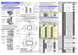
Terminal Wiring
CAUTION: Check information label on housing for correct operating voltage
before connecting supply to Power Inputs.
Diagrams show all possible option combinations, check your exact
product specification before connecting.
1
RS485
A (Rx/Tx+)
Serial
Comms
2
RS485
B (Rx/Tx-)
3
Relay COM / Linear +
Output 3
4
Relay NO / Linear -
5
Relay COM / SSR -
Output 2
6
Relay NO / SSR +
7
L +
Mains Power
(24V optional)
8
N -
9
- Volt-free or TTL
Digital Input
10
+ compatible
16
Relay NC
Output 1
11
Relay COM / SSR -
12
Relay NO / SSR +
13
RTD
Input –
thermocouple,
RTD or linear
14
RTD / TC + / Linear +
15
RTD / TC - / Linear -
* NEVER DIRECTLY CONNECT DEDICATED CONFIGURATION SOCKET TO A USB PORT.
2. FRONT PANEL
Display shows PV (process variable),
units, SP (setpoint), alarm/latch
statuses, error & warning messages
.
D
isplay turns off after 5, 15 or 30
minutes without
key press.
Navigation & Editing
Press or keys to navigate between parameters or menu items.
Press to highlight and edit a parameter value.
Press or to change the parameter value, then press within 60 seconds to
confirm change.
For example, changing the setpoint (
SP).
Navigating to Setup Mode or Advance Configuration from Operator Mode:
Setup Mode - press & .
Advanced Configuration - press & .
Returning to Operator Mode:
Press & to move back one level. After 120 seconds without key presses the unit
returns automatically to the first Operator Mode screen.
3. SETUP (& FIRST POWER UP)
Important Note: When powered up for the first time, or after a factory reset (default) the
instrument enters Setup.
The device remains in Setup, or will keep powering up back into Setup, until
all
parameters have been reviewed and the user
exits Setup.
Some parameters may be hidden depending on configuration & hardware.
Alternatively press & to enter Setup from Operator mode and & to exit.
Setup Lock
Enter code & press
Default 10
Parameter
Description
Default Value
>Input
Type
J Thermocouple *
K Thermocouple
-200 – 1200ºC
-328 – 2192ºF
-128.8 – 537.7ºC
-199.9 – 999.9ºF
K Thermocouple *
-240 – 1373ºC
-400 – 2503ºF
-128.8 – 537.7ºC
-199.9 – 999.9ºF
PT100 *
-199 – 800ºC
-328 – 1472ºF
-128.8 – 537.7ºC
-199.9 – 999.9ºF
B Thermocouple
100 – 1824ºC
211 – 3315ºF
C Thermocouple
0 – 2320ºC
32 – 4208ºF
L Thermocouple *
0 – 762ºC
32 – 1403ºF
0.0 – 537.7ºC
32.0 – 999.9ºF
N Thermocouple
0 – 1399ºC
32 – 2551ºF
R Thermocouple
0 – 1795ºC
32 – 3198ºF
S Thermocouple
0 – 1762ºC
32 – 3204ºF
T Thermocouple *
-240 – 400ºC
-400 – 752ºF
-128.8 – 400.0ºC
-199.9 – 752.0ºF
Linear dc
0 – 50mV
>Input
Units
°C or °F (hidden when a linear input is used)
°C
* Maximum of 1 decimal place for temperature inputs marked.
>Input
Decimal Place
0000 *
000.0 *
00.00
0.000
0000
Scale Range max & min only visible when input is a linear type.
>Input
Scale Range Maximum
Maximum for application working range. 1000
>Input
Scale Range Minimum
Minimum for application working range. 0
>Input
Digital I/P Action
None
Alarm Reset (clears latched alarms)
Ctrl Enable/Disable (disables control)
Ctrl Auto/Manual
Pre-Tune Start/Stop
Tune at SP Start/Stop
Ctrl
Enable/Disable
>Output 1
Usage
Heat
Cool
Non Linear Cooling
Alarm 1
Alarm 2
Alm. 1or2
Loop Alarm
Heat
Control Loop Alarm time is 2x Integral (PID) or Loop Alarm Time (if mode is On.Off)
>Output 2
Usage
Same options as Output 1 Usage
Alarm 1
>Output 3
Usage
or
>Linear Outp
Usage
Same options as Output 1 Usage.
Heat
Cool
PV Retx
SP Retx
Alarm 2
PV Retx
>Linear Outp
Type
0-10V
2-10V
0-20mA
4-20mA
0-5V
1-5V
0-10V
>Linear Outp
Scale Range Maximum
Maximum PV value corresponding to
maximum linear output. Input type Max
>Linear Outp
Scale Range Minimum
Minimum PV value corresponding to
minimum linear output. Input type Min
>Alarm 1
Value
Range minimum to range maximum, or OFF
(maximum +1). OFF disables alarm.
Default
PV High
alarm type.
1373
>Alarm 2
Value
Same options as Alarm 1.
Default PV Low alarm type.
-240
Setpoint
Target setpoint.
0
>Coms Unit Address
Modbus address from 1 to 255
1
>Coms Baud Rate
1200, 2400, 4800, 9600, 19200 & 38400
9600
>Coms Parity
Odd, Even or None
None
>Control
Automatic Tuning
Off
,
Start Pre-Tune
or
Start Tune at SP *
Off
*Start Tune at SP not available for Heat & Cool processes.
When you exit if necessary, press and to clear Control is Enabled Pop Up Alert.
4. OPERATOR MODE
Name
Details
User Screen
PV - top
SP - bottom
Temperature Unit - right.
Manual control
Manual Power is shown as
P%
.
Important: Visibility for parameters below must be set to
Show
in
Operator
sub-menu.
Alarm State
To clear
latches press
then to select
Yes.
Press to
accept.
Alarm active
Alarm set, but not
active
Alarm not set
Latch State
Output Latched
Latch set, but
output not Latched
Latch not set
Maximum PV
To clear press then to select
Yes. Press to accept.
Screens show the
Maximum & Minimum PV
reached.
Minimum PV
Control Enable
OFF - Control output(s) disabled. (Ignored in manual mode).
ON
- Control output(s) enabled.
Manual Control
Enable
OFF - Automatic control, PID or On-Off control available.
ON - Manual control, Manual Power shown as P% xxx.
Warnings & Error Messages
Caution: Do not continue your process until any issues are resolved.
Name
Details
Pop up Alerts:
Warnings and
Confirmations
For example, Pop Up Alert for Alarm 1.
Pop Up Alerts need to be acknowledged.
Press and to clear Pop Up Alert.
Pop up Alerts: Alarm 1, Alarm 2, Alarm 1 & 2, Starting Calibration, Calibration Ongoing,
Calibration Fail
,
Control is Enabled
,
Tune Error
messages,
Tuning in progress, Setup
not Completed & Offset in use (SP offset).
ALARM
Alternates with PV to show Alarm is active.
LATCH
Alternates with PV.
One or more outputs are latched on and no alarm is active.
HIGH
Process variable input > 5% over-range.
LOW
Process variable input > 5% under-range.
OPEN
Break detected in process variable input sensor, wiring or wrong
input type selected. Shows OPEN
until resolved, control is off.
ERROR
Selected input range is not calibrated.
Shows ERROR
until resolved, control is off.
TUNE
Alternates with SP. Auto-tuning is in progress.
P%
Manual power value replaces setpoint, shows P% xxx of power.
Ramp
Alternates with actual setpoint. Setpoint ramp is active.
OFF
Control is disabled. Control output(s) are off.
Control Delayed
Visible when Delay Timer is active. Control output(s) are off.
Tuning in progress
Alternates with setpoint. Tuning is active.
Tune Errors
Display alternates between Tune Error & Setpoint.
Remains visible until Automatic Tuning is turned Off.
tErr1
PV within 5% of SP (for pre-tune)
tErr2
Setpoint is ramping
tErr3
Control is ON/OFF (not PID)
tErr4
Control is manual
tErr5
Tune at Setpoint not able to run
tErr6
Sensor Break
tErr7
Timer Running
tErr8
Control is Disabled
5. SPECIFICATIONS
Important: Check your product code for exact hardware fitted.
PROCESS INPUT
Thermocouple
Calibration:
±0.25% of full range, ±1LSD & ±1°C for Thermocouple CJC.
Factory calibration
is accurate 0.25% of span above -100°C, below -100°C
a
ccuracy is within +/- 0.9%. To meet 0.25% accuracy below -100°C
recalibrate using procedure in full manual.
BS4937, NBS125 & IEC584.
PT100 Calibration:
±0.25% of full range, ±1LSD.
BS1904 & DIN43760 (0.00385
Ω
/
Ω
/°C).
DC Calibration:
±0.25% of full range, ±1LSD.
Sampling Rate:
4 per second.
Impedance:
>1MΩ resistive, except dc mA (5Ω) and V (47kΩ)
Sensor Break Detection:
Thermocouple, RTD, 4 to 20mA, 10 to 50mV, 2 to 10V and 1 to
5V ranges only. Control outputs turn off at sensor break.
DIGITAL INPUT (Isolated or Non-Isolated version)
Functions:
Reset Alarm
,
Control Enable
/
Disable
,
Auto/Manual
,
Pre-Tune
Start/Stop or Tune at SP Start/Stop.
Signal:
Non
-isolated - Open or Close only.
Isolated
- Open (2 to 24Vdc) or Closed (<0.8Vdc).
Open to Closed transition = Reset, Enabled, Auto or Start.
OUTPUTS
Relay Contacts:
Form C SPDT (Op 1) / Form A SPST relay (other), 2A @ 250Vac.
Relay Lifetime:
>150,000 operations at rated voltage/current, resistive load.
SSR Driver Capability:
SSR drive voltage >10V at 20mA
DC Linear (Output 3 option only):
Types:
Accuracy:
0 to 20mA, 4 to 20mA, 0 to 5V, 0 to 10V or 2 to 10V
±
0.25% (mA @ 250Ω, V @ 2kΩ). Degrades linearly to ±0.5% for
increasing burden (to specification limits).
Load Resistance:
Current Output 500Ω max, Voltage Output 500Ω min.
Resolution:
8 bits in 250ms (10 bits in 1s typical, >10 bits in >1s typical).
RS485 SERIAL COMMUNICATIONS (Modbus RTU)
Data Rate:
1200, 2400, 4800, 9600, 19200 or 38400 bps.
OPERATING CONDITIONS
Usage:
For indoor use only, DIN-rail mounted in suitable enclosure.
Ambient Temp:
<95% humidity 0°C to 55°C (Operating), –10°C to 80°C (Storage).
Relative Humidity:
20% to 95% non-condensing.
Altitude:
< 2000m
Power Supply:
Mains power version - 100 to 240Vac ±10%, 50/60Hz, 9VA
Low voltage version
- 24Vac +10/-15% 50/60Hz 9VA or 24Vdc
+10/-15% 5W.
ENVIRONMENTAL
Standards:
CE, UL & cUL.
EMI:
EN61326-1:2013, Table 2 & Class A.
Warning: This is a Class A product. In a domestic environment, this product may cause
radio interference in which case the user may be required to take adequate measures.
Safety:
UL61010-1 Edition 3, EN61010-1 Version 2010,
Pollution Degree 2 & Installation Class 2.
Protection Rating:
IP20.
PHYSICAL
Unit Size:
Height - 99mm; Width – 22.5mm; Depth - 121mm
Ventilation:
A space of 80mm must be allowed above & below each unit.
Weight:
0.20kg maximum
ISOLATION
PSU
Universal
Input
Relay
SSR
Linear
RS485
Comms
Non-
Isolated
Digital
Input
Isolated
Digital
Input
Config
Port
PSU
Universal Input
Relay
SSR
Linear
RS485 Comms
Non-Isolated Digital Input
Isolated Digital Input
Configuration Port
Not Applicable
No Isolation
Reinforced Isolation
6. SAFETY & WARNING SYMBOLS
Risk of electric shock.
Caution, refer to the manual.
Alternating or direct current
could be present.
Equipment protected
through-out by double
insulation.
Bus
Connector
pin-outs:
* Dedicated
configuration port
Data B
Data A
Data B
Data A
Up
Down
Ok /
Select
Bus Connector (optional)
Mounting & Unmounting
Alarm State
Alarm 1
Alarm 2
Loop
Latch State
Out 1
Out 2
Out 3
Fixed LEDs - Heat, Cool & Alarm:

59627 MaxVU Rail Extrusion Controller Concise manual (EN)
Alarm State
Alarm 1
Alarm 2
Loop
Latch State
Out 1
Out 2
Out 3
7. ADVANCED CONFIGURATION
Advanced Configuration gives access to all possible parameters; however, the device
hides parameters that are irrelevant to your exact product specification & configuration.
Advanced Configuration Navigation
Enter by pressing & . Press or to navigate to the required menu, then press
to enter.
Press & to exit up 1 level. Depending upon which menu you enter it may be
necessary to exit 2 or 3 levels for Operator Mode.
Advanced Configuration menus
Advanced Lock
Enter code & press
Default 20
Menus
Description
User
Includes Status, Control & Manual Mode enable/disable.
Input
Configure the process input.
User Calibration
Single or two-point calibration adjustments for the process input.
Outputs
Configuration parameters for the outputs.
Control
PID control tuning & configuration parameters.
Setpoint & Timer
Setpoint & timer settings.
Alarms
Alarm configuration.
Communication
Modbus communications settings.
Display
Lock codes and Factory Default.
Operator Screens
Control what appears in Operator Mode.
Information
View serial number & manufacturing details.
User menus
Parameter
Description
Default Value
Alarm State
Alarm active
Alarm set, but not
active
-
Alarm not set
n/a
Latch State
Output
Latched
Latch set but output
not Latched
-
Latch not set
To clear press
then
to select Yes.
Press to accept.
n/a
Maximum PV
Maximum and Minimum PV recorded
whilst powered up or since last reset.
To clear press then to select Yes.
Press to accept.
n/a
Minimum PV
Control Enable
OFF - Control output(s) disabled. (Ignored
when in manual mode) SP replaced by
OFF
.
ON
ON - Control output(s) enabled. Setpoint
visible in User screen.
Manual Control
Enable
OFF - Instrument in automatic control mode
(PID or On-Off control).
OFF
ON - Manual control ON. Power shown as
Pxxx % in Operator mode, in place of SP.
Input menu
Parameter
Description
Default Value
Input Type
See Input Type table in SETUP (& FIRST
POWER UP).
K Thermocouple
Units
Displayed as °C or °F
(Units are hidden when a linear input is used)
°C
Decimal Place
0000
0000
000.0
00.00
Not for temperature.
0.000
Scale Range
Maximum
Maximum for application working range
Max allowed for
Input Type.
Scale Range
Minimum
Minimum for application working range
Min allowed for
Input Type.
Filter Time
OFF or 0.5 to 100.0 seconds in 0.5
increments
2.0
CJC Enable
Enable Enables the internal thermocouple
CJC (Cold Junction Compensation).
Enable
Disable Disables the internal CJC.
External compensation must be provided for
thermocouples.
Digital I/P Action
None
Alarm Reset (clears latched alarms)
Ctrl Enable/Disable
Ctrl Auto/Manual
Pre-Tune Start/Stop
Tune at SP Start/Stop (not available for
heat/cool)
Ctrl
Enable/Disable
User Calibration menu
Single-point offset or two-point calibration adjustment for process input. Can be used
together, if required.
Parameter
Description
Default Value
Offset
Shifts the input value up or down by a single offset
amount across the entire range.
0
Low Point
Enter value at which the low point error was measured.
Lower Limit
Low Offset
Enter equal, but opposite offset value to the observed
low point error.
0
High Point
Enter value at which the high point error was measured.
Upper Limit
High Offset
Enter an equal, but opposite offset value to the
observed high point error.
0
Outputs menu
Parameter
Description
Default
Value
>Output 1
Usage
Heat
Cool
Non Linear Cooling
Alarm 1
Alarm 2
Alm. 1or2
Loop Alarm
Heat
Control Loop Alarm is set as 2x Integral (PID) or Loop Alarm Time (On.Off control)
Alarm Action
Direct - Output active when alarm triggers
Reverse
- Output active when alarm is not
triggered
Direct
Latching
Off - Alarm doesn’t latch
On
– Alarm latches & needs to be cleared
Off
LED Indicator
Direct - LED Indicator lit when output is active
Reverse
- LED Indicator lit when output is
inactive
Direct
>Output 2
Usage
Same options as Output 1 - Usage
Alarm 1
Alarm Action
Same options as Output 1 - Alarm Action
Direct
Latching
Same options as Output 1 - Alarm Latching
Off
LED Indicator
Same options as Output 1 - LED Indicator
Direct
>Output 3
or >Linear Outp
3rd output - either Relay/SSR driver (Output 3) or Linear.
>Output 3
Usage
>Linear Outp
Usage
Output 3 - same options as Output 1 -
Usage
Heat
Cool
PV Retransmit
SP Retransmit
Output 3
:
Alarm 2
Linear:
PV
Retransmit
>Output 3 Alarm Action
Same options as Output 1 - Alarm Action
Direct
>Output 3 Alarm
Latching
Same options as Output 1 - Alarm Latching
Off
>Output 3 LED Indicator
Same options as Output 1 - LED Indicator
Direct
>Linear Outp
Type
0-10V
2-10V
0-20mA
4-20mA
0-5V
1-5V
0-10V
>Linear Outp
Scale Range Maximum
Display value for maximum output, -1999 to 9999
Input type
Max
>Linear Outp
Scale Range Minimum
Display value for minimum output, -1999 to 9999
Input type
Min
Control menu
PID control tuning & configuration & Loop Alarm. Hidden if no control outputs are set.
Parameter
Description
Default
Value
Proportion Heat
Band
ON/OFF (0.0) or PID control in display units.
1 to 9999 - 0 decimal places
0.1 to 999.9 - 1 decimal place
0.01 to 99.99 - 2 decimal places
0.001 to 9.999 - 3 decimal places
161
Proportion Cool
Band
161
Auto Reset (Integral)
0.01 to 99.59.
and OFF (0.00) (minutes & seconds).
5.00
Rate (Derivative)
0.01 to 99.59 or OFF (0.00) (minutes & seconds).
1.15
Overlap/
Deadband
In display units, range -20 to +20% of Heat & Cool
Proportional Band.
0
is Off.
0
Differential
(On/Off)
Visible when using On/Off control.
In display units centred about the setpoint.
Range: 0.1% to 10.0% of input span
8
Loop Alarm Time
Visible when On/Off control & Loop Alarm assigned to
an output.
Sets time before the loop alarm triggers.
(minutes & seconds)
99.59
Parameter
Description
Default
Value
Manual Rst (Bias)
Manual Reset 0 to 100%
(-100%
to 100% if heat/cool control)
25%
Soft Start Time
0:01 to 60:00 or OFF (0:00)
(hours & minutes)
OFF
Soft Start Setpoint
See Soft Start diagram.
-240
Heat Cycle Time
0.1
to
512.0
seconds
32.0
Cool Cycle Time
32.0
Output Interlock
Prevents simultaneous activation of both heat & cool
outputs. On / Off
Only set to On if Overlap/Deadband = 0.
Off
Heat Power Limit
% power upper limit 0 to 100%
100%
Cool Power Limit
% power upper limit 0 to 100%
100%
Power Up Action
Last - Powers up with control enable in the same state
as on power off or power failure.
On - Always powers up with control enabled.
Off - Always powers up with control disabled.
Last
Automatic Tuning
Off
Start Pre-Tune
Start Tune at SP *
Off
*Start Tune at SP not available for Heat & Cool process.
Setpoint menu
Parameter
Description
Default Value
Ramp Rate
Rate actual setpoint changes from current PV to
target setpoint following power-up or control enable.
From
0.001
to
9999.
or
OFF
(
10 000
) (Units / hr).
Any setpoint changes also follow this rate.
OFF
Upper Limit
Used to limit the Maximum setpoint value.
Scale Range
Maximum
Lower Limit
Used to limit Minimum setpoint value.
Scale Range
Minimum
Offset
Offsets the setpoint. For use in multi-zone setpoint
slave applications.
Offset in use pop-up appears when SP is changed.
0
Soft Start diagram
① At power on the unit will control to the Soft Start Setpoint.
② Then remain at this value for the time defined by the Soft Start Time. During this
period the control cycle time is ¼ of the value entered and the Heat Power Limit is used.
③ When soft start timer expires the unit returns to normal operation. It controls to the
normal setpoint & from this point the Heat Power Limit is not used by the controller.
Non Linear Cooling diagram
With non-linear cooling, the cooling curve adjusts the output power so that the effective
power over 0% to -70% is weaker, by adjusting the % on vs off time.
① At power on the unit will control to the Soft Start Setpoint.
② Then remain at this value for the time defined by the Soft Start Time. During this
period the control cycle time is ¼ of the value entered and the Heat Power Limit is used.
③ When soft start timer expires the unit returns to normal operation. It controls to the
normal setpoint & from this point the Heat Power Limit is not used by the controller.
Alarms menu
Parameter
Description
Default Value
>Alarm 1
Type
None
PV High
PV Low
Deviation
Band
PV High
Value
Range minimum to range maximum, or
OFF (maximum +1). OFF disables
alarm. Default PV High alarm type.
1373
Hysteresis
0 to full span.
1
>Alarm 2
Type
Same options as Alarm 1
PV Low
Value
-240
Hysteresis
1
>Options
Alarm Inhibit temporarily deactivates alarms at power-up & on change in setpoint.
Alarm Inhibit
None
Alarm 1
Alarm 2
Alarm 1 & 2
None
Alarm PV Notification
None
Alarm 1
Alarm 2
Alarm 1
&
2
Alarm 1
&
2
Sensor Break Alarm
On - activates both alarms, if
configured, when a sensor break is
detected.
Off
Communications menu
Modbus communications settings, only shown when RS485 option is fitted.
Parameter Name
Description
Default Value
Unit Address
Modbus address from 1 to 255
1
Baud Rate
Coms data rate in kbps
1200, 2400, 4800, 9600, 19200 & 38400.
9600
Parity
Parity checking: Odd, Even or None
None
Display menu
Lock codes & Factory Defaults.
Parameter Name
Description
Default Value
Setup Unlock Code
View & adjust Setup lock code.
From 1 to
9999 or Off for no lock code.
10
Advanced Unlock
Code
View & adjust Advanced lock code.
From 1 to
9999 or Off for no lock code.
20
Screen Timeout
Screensaver time 5, 15 or 30 mins.
5
Selected language
Display language, 2 available – English plus either
German or French.
English
Reset to Defaults
Reset parameters back to factory defaults.
To clear press then to select Yes.
Press to accept.
Operator Screens menu
Controls what appears in Operator Mode.
Parameter Name
Description
Default Value
Control Enabled
Hide
or
Show
parameters in Operator
Mode.
Hide
Manual Ctrl Enabled
Hide
Alarm State
Hide
Latch State
Show
Maximum PV
Hide
Minimum PV
Hide
Information menu (Read-Only)
Parameter Name
Description
PRL
DOM
The hardware/software revision level.
Date of manufacture (mmyy).
FW Version
FW Type
The firmware version number & code type.
Serial
Instrument serial number.
Out1
Out2
Out3
SSR (SSR driver) or Relay
SSR (SSR driver) or Relay.
None, SSR (SSR driver), Relay or Linear.
Comm
DI
Comms option - Fitted or None.
Digital Input options – Iso (isolated) or NonIs (non-isolated).
Please refer to the full manual for further information on any topic.
/