Arctic Cat Pantera 3000 User manual
- Category
- Engine
- Type
- User manual

www.arcticcat.com
SERVICE MANUAL
www.
a
r
c
ti
cca
t.
com
®
®
®
®
®

1
ZR/XF/M/Pantera 3000/5000/7000/9000
TABLE OF CONTENTS
General Information/Foreword .................................................. 2
Snowmobile Identification ..................................................... 2
Recommended Gasoline and Oil .......................................... 2
Engine Break-In .................................................................... 3
Drive Belt Break-In ................................................................ 3
Genuine Parts ....................................................................... 3
Varying Altitude Operation .................................................... 3
Preparation For Storage........................................................ 5
Preparation After Storage ..................................................... 6
After Break-In Checkup/Checklist ......................................... 6
Engine Specifications............................................................ 8
Electrical Specifications ........................................................ 9
Drive System Specifications................................................ 10
Drive Clutch/Driven Clutch-Related Specifications ............. 10
Drive System Components ................................................. 10
Chain Case Performance Calibrations ................................ 11
Track Specifications ............................................................ 13
Suspension Specifications .................................................. 13
Torque Conversions ............................................................ 13
Torque Specifications .......................................................... 14
Steering and Body .................................................................... 15
Steering Post....................................................................... 15
Ski (ZR/XF/Pantera)............................................................ 19
Ski (XF HC/M) ..................................................................... 20
Ski Wear Bar ....................................................................... 20
Spindle (ZR/XF/Pantera)..................................................... 21
Spindle (XF HC/M) .............................................................. 21
Steering Tie Rod ................................................................. 22
Ski Alignment ...................................................................... 23
A-Arms (ZR/XF/Pantera)..................................................... 24
A-Arms (XF HC/M).............................................................. 25
Ski Shock Absorber............................................................. 27
Sway Bar............................................................................. 27
Front Bumper ...................................................................... 27
Seat Assembly .................................................................... 28
Seat Cushion ...................................................................... 28
Taillight/Brakelight Assembly............................................... 29
Rear Bumper/Snowflap ....................................................... 29
Windshield/Console/ Headlight ........................................... 29
Headlight Bulb..................................................................... 31
Adjusting Headlight Aim ..................................................... 31
Engine ........................................................................................ 32
Engine Removing/Installing - 3000 ..................................... 32
Engine Removing/Installing - 5000/9000 ............................ 41
Engine Removing/ Installing - 7000 .................................... 57
Engine Servicing - 3000...................................................... 64
Engine Servicing - 5000/9000............................................. 88
Assembly Schematic - 5000/9000..................................... 111
Engine Servicing - 7000.................................................... 114
Assembly Schematic - 7000.............................................. 133
Troubleshooting Engine..................................................... 135
Engine-Related Items ............................................................. 137
Water Pump ...................................................................... 137
Pressure Testing Engine ................................................... 142
Checking Compression ..................................................... 142
Changing Oil/Filter ............................................................ 143
Testing Oil Pressure.......................................................... 145
Liquid Cooling System (5000/9000) .................................. 146
Liquid Cooling System (3000/7000) .................................. 147
Cooling System Schematics ............................................. 148
Air Silencer........................................................................ 150
Turbocharger/Intercooler (9000)........................................ 151
Fuel Systems........................................................................... 156
Fuel System ...................................................................... 156
Individual Components...................................................... 156
Self-Diagnostic System/Codes.......................................... 160
Fuel Pressure Regulator ................................................... 161
Throttle Body Assembly .................................................... 161
Throttle Cable.................................................................... 168
Fuel Pump......................................................................... 168
Troubleshooting................................................................. 171
Gas Tank........................................................................... 172
Electrical Systems .................................................................. 174
Ignition System.................................................................. 174
Throttle Position Sensor .................................................... 174
Electrical Resistance Tests (3000).................................... 177
Electrical Resistance Tests (5000/9000)........................... 178
Electrical Resistance Tests (7000).................................... 178
Voltage Regulator Tests .................................................... 179
Testing Fuel Gauge Sender .............................................. 179
Emergency Stop Switch .................................................... 180
Starter Relay Solenoid ...................................................... 180
Fuse .................................................................................. 180
Ignition Switch ................................................................... 180
Starter Motor ..................................................................... 181
Troubleshooting Electric Start ........................................... 186
Magneto ............................................................................ 186
Brakelight Switch............................................................... 189
Headlight Dimmer Switch.................................................. 190
Testing Handlebar Warmer Elements .............................. 190
Testing Thumb Warmer Element....................................... 191
Testing Handlebar Warmer/Thumb Warmer Switch .......... 191
Testing Passenger Handwarmer Switch ........................... 191
Testing Passenger Handwarmer Elements ....................... 191
Testing Seat Heater Switches ........................................... 192
Testing Speedometer Sensor............................................ 192
Testing Gear Position Switch............................................. 192
Testing Shift Switch ........................................................... 193
Testing Shift Actuator ........................................................ 193
Testing Heated Shield Outlet............................................. 193
Voltage/Resistance Chart - Air Temperature..................... 194
Voltage/Resistance Chart - Coolant Temperature............. 194
Drive Train/Track/Brake Systems .......................................... 195
Drive Belt........................................................................... 195
Drive Clutch....................................................................... 196
Driven Clutch..................................................................... 199
Drive Clutch/Driven Clutch ................................................ 203
Drive Train ......................................................................... 205
Drive Sprockets ................................................................. 211
Track Tension .................................................................... 213
Track Alignment................................................................. 213
Brake System (Hydraulic) ................................................. 214
Brake Lever/Master Cylinder Assembly ............................ 220
Troubleshooting Drive Clutch/Driven Clutch...................... 221
Troubleshooting Track ....................................................... 222
Troubleshooting Hydraulic Brake System.......................... 222
Suspension.............................................................................. 223
Suspension Setup Basics ................................................. 223
Servicing Suspension ....................................................... 228
FOX Air Shocks................................................................. 242
Servicing IFP Shock.......................................................... 242

2
General
Information/Foreword
NOTE: General specifications for each 2016 Arctic
Cat Snowmobile can be accessed from the Arctic Cat
Cat Tracker Dealer Communication System online.
NOTE: Some illustrations and photographs used in
this manual are used for clarity purposes only and are
not designed to depict actual conditions.
This Arctic Cat Service Manual contains service and
maintenance information for certain Model Year 2016
Arctic Cat Snowmobiles (see cover). The manual is
designed to aid service personnel in service-oriented
applications.
This manual is divided into sections. The sections cover
specific snowmobile components or systems and, in
addition to the standard service procedures, includes
assembling, disassembling, and inspecting instructions.
When using this manual as a guide, the technician should
use discretion as to how much disassembly is needed to
correct any given condition.
The service technician should become familiar with the
operation and construction of the components or systems
by carefully studying the complete manual. This will
assist the service technician in becoming more aware of
and efficient with servicing procedures. Such efficiency
not only helps build consumer confidence but also saves
time and labor.
All Arctic Cat publications and snowmobile decals dis-
play the words Warning, Caution, and Note to emphasize
important information. The symbol ! WARNING
identifies personal safety-related information. Be sure to
follow the directive because it deals with the possibility
of severe personal injury or even death. A CAUTION
identifies unsafe practices which may result in snowmo-
bile-related damage. Follow the directive because it deals
with the possibility of damaging part or parts of the
snowmobile. The symbol NOTE: identifies supple-
mentary information worthy of particular attention.
At the time of publication, all information, photographs,
and illustrations were technically correct. Some photo-
graphs and illustrations used in this manual are used for
clarity purposes only and are not designed to depict
actual conditions. Because Arctic Cat Inc. constantly
refines and improves its products, no retroactive obliga-
tion is incurred.
All materials and specifications are subject to change
without notice.
Keep this manual accessible in the shop area for refer-
ence.
Product Service and Warranty Department
Arctic Cat Inc.
Snowmobile Identification
The Arctic Cat Snowmobile has two important identifica-
tion numbers. The Vehicle Identification Number (VIN)
is stamped into the tunnel near the right-side footrest or
on top of the tunnel. The decal also displays pertinent
production information. The Engine Serial Number
(ESN) is stamped into the crankcase of the engine.
These numbers are required to complete warranty claims
properly. No warranty will be allowed by Arctic Cat if
the engine serial number or VIN is removed or mutilated
in any way.
Recommended Gasoline
and Oil
RECOMMENDED GASOLINE
(3000/5000/7000)
The recommended gasoline to use in these snowmobiles
is 87 octane regular unleaded. In many areas, oxygenates
are added to the gasoline. Oxygenated gasolines contain-
ing up to 10% ethanol are acceptable gasolines.
When using ethanol blended gasoline, adding a gasoline
antifreeze is not necessary since ethanol will prevent the
accumulation of moisture in the fuel system.
RECOMMENDED GASOLINE (9000)
The recommended gasoline to use in these snowmobiles
is 91 octane (minimum).
NOTE: If a situation arises in which 91 octane gaso-
line is not available, 87 octane gasoline can be substi-
tuted; however, do not prolong the usage of 87 octane
gasoline as it will cause poor engine performance.
In many areas, oxygenates are added to the gasoline.
Oxygenated gasolines containing up to 10% ethanol are
acceptable gasolines. Do not use gasolines containing
methanol.
RECOMMENDED OIL
(3000/5000/9000)
The recommended oil to use is Synthetic 0W-40 Oil in all
temperatures and conditions.
CAUTION
Do not use white gas or gasoline containing methanol.
Only Arctic Cat approved gasoline additives should be
used.
CAUTION
Any oil used in place of the recommended oil may
cause serious damage.

3
OILCHARTJ
After the engine break-in period, the engine oil should be
changed every 2500-3000 miles (3000/5000) or
1500-2000 miles (9000) and before prolonged storage.
RECOMMENDED OIL (7000)
The recommended oil to use is Synthetic C-TEC4 Oil
(p/n 6639-529 - gal.).
After the engine break-in period, the engine oil should be
changed every 2500 miles before prolonged storage and
the oil filter should be changed every 12,000 miles.
Engine Break-In
3000/5000/9000
The Arctic Cat 4-stroke engine (when new or rebuilt)
requires a short break-in period before the engine is sub-
jected to heavy load conditions.
This engine does not require any pre-mixed fuel during
the break-in period.
To ensure trouble-free operation, careful adherence to the
following break-in guidelines will be beneficial.
* With occasional full-throttle operation.
To ensure proper engine break-in, Arctic Cat recom-
mends that the engine oil and filter be changed after 500
miles or after one month, whichever comes first. This
service is at the discretion and expense of the snowmo-
bile owner.
7000
The engine (when new or rebuilt) requires a short
break-in period before the engine is subjected to heavy
load conditions.
This engine does not require any pre-mixed fuel during
the break-in period.
There is never a more important period in the life of the
engine than the first 500 km (300 miles).
Since the engine is brand new, do not put an excessive
load on it for the first 500 km (300 miles). The various
parts in the engine wear and polish themselves to the cor-
rect operating clearances. During this period, prolonged
full throttle operation or any condition that might result
in engine overheating must be avoided.
Operating your snowmobile for the first time: Start the
engine and let it idle for 15 minutes.
0-160 km (0–100 miles): Avoid prolonged operation
above 6000 RPM.
160-500 km (100–300 miles): Avoid prolonged operation
above 8000 RPM.
500 km (300 miles) and beyond: The snowmobile can
now be operated normally.
NOTE: After 800 km (500 miles) of operation, the
engine oil must be changed and the oil filter replaced.
If any engine trouble should occur during the engine
break-in period, immediately have an Arctic Cat
dealer check the snowmobile.
Drive Belt Break-In
Drive belts require a break-in period of 25 miles. Drive
the snowmobile for 25 miles at 3/4 throttle or less. By
revving the engine up and down (but not exceeding 60
mph), the exposed cord on the side of a new belt will be
worn down. This will allow the drive belt to gain its opti-
mum flexibility and will extend drive belt life.
NOTE: Before starting the snowmobile in extremely
cold temperatures, the drive belt should be removed
and warmed up to room temperature. Once the drive
belt is at room temperature, install the drive belt (see
Drive Belt sub-section in the Drive Train/Track/Brake
Systems section of this manual).
Genuine Parts
When replacement of parts is necessary, use only genuine
Arctic Cat parts. They are precision-made to ensure high
quality and correct fit.
Varying Altitude Operation
Operating a snowmobile at varying altitudes requires
recalibration of drive system components.
Consult the appropriate specification sheet on Cat
Tracker Online.
Following are basic altitude theories for clutching,
engine, suspension, and track.
CAUTION
DO NOT use premixed fuel in the snowmobile gas tank.
Engine damage will occur.
0-200 miles (3000) 1/2 Throttle (30 MPH-max)
0-200 miles (5000/9000) 1/2 Throttle (45 MPH-max)
200-400 miles 1/2-3/4 Throttle
400-600 miles 1/2-3/4 Throttle *
CAUTION
Running the engine with the drive belt removed could
result in serious engine damage and drive clutch failure.

4
CLUTCHING
On a normally-aspirated engine as altitude changes,
engine horsepower changes with it. As you go up in alti-
tude, the engine loses horsepower. Because of this, the
continuously variable transmission (CVT) system needs
to be calibrated to compensate for the horsepower loss.
At altitudes above 5000 ft, the engine loses peak horse-
power but will also lose horsepower at engagement
speed. For this reason, calibrating the drive system is
usually needed in order to attain acceptable performance.
Changing drive clutch engagement speed can be done
several ways. Some of the methods will affect other char-
acteristics of CVT operation, so you must be careful what
you change. Drive clutch springs are the most common
way to increase engagement speed; however, by simply
changing the cam arms to a lighter weight from the
heavier sea level cam arm, you will gain some engage-
ment speed.
Other more complicated methods exist such as engage-
ment notches and changing the position of the cam arm
center of gravity in relation to the roller. This is called
“tucking the weight” and can be used, but, like the
engagement notch, it can hurt belt life.
The driven clutch will also play a part in CVT tuning for
high altitude operation. A steeper helix (torque bracket)
angle in the driven clutch will mean a quicker up-shift. A
shallower angle will mean a slower up-shift. If the
up-shift is too quick, due to a very steep helix, RPM will
be pulled down under the peak operating RPM of the
engine (where the horsepower is) and performance will
suffer. The engine may even bog. If you have a helix that
is too shallow, the engine may over-rev or have poor
acceleration. Usually, angles shallower than the sea level
calibrations work best. The driven spring will also affect
driven clutch tuning. Tighten the spring, and RPM will
increase. Loosen the spring, and RPM will decrease. The
spring should be used to fine-tune and complement the
helix selection.
Carburetor calibration changes for high altitude operation
will have an effect on the CVT system and how it oper-
ates. Understanding the basics of CVT operation is
important in order to make the correct high altitude CVT
calibration changes.
ENGINE
A normally aspirated engine will generate more horse-
power at sea level than it does at higher altitudes. The
reason is that the higher you go, less oxygen is available
for the engine to use during its combustion process. Less
oxygen means it needs less fuel to obtain the correct
air/fuel ratio to operate properly. This is why the fuel
ratio has to be recalibrated. High altitude engines operate
as though they have a lower compression ratio. This,
along with less oxygen and less fuel, means that the
engine generates less horsepower. All of these character-
istics will become more evident the higher the altitude.
TURBOCHARGING
Turbocharging is one method of compensating for loss of
air density that works extremely well when applied to
four-cycle internal combustion engines.
Exhaust gasses are directed through the turbocharger tur-
bine wheel which is attached to the compressor through a
common shaft. As the exhaust gasses spin the turbine, the
compressor is spun at very high RPM. Inlet air is drawn
into the compressor, compressed, and routed to the intake
manifold of the engine. Intake pressure, therefore, is
maintained at the optimum level as altitude or tempera-
ture increases.
The turbocharger output must be regulated to maintain
the optimum manifold pressure throughout the designed
operating range. This is accomplished by regulating the
volume of exhaust gasses passing through the turbine by
controlling a diverter valve (waste gate) at the turbo-
charger turbine inlet. At lower altitudes/temperatures,
excessive exhaust gasses are diverted past the turbine and
into the exhaust downstream of the turbocharger thus
limiting the compressor output to maintain correct mani-
fold pressure.
As altitude increases, the manifold pressure is held con-
stant by diverting less exhaust past the turbine, thus
increasing compressor speed. This will continue until the
waste-gate is completely closed at which time manifold
pressure will start to decrease much the same as a nor-
mally aspirated engine.
The waste gate is controlled by a spring/diaphragm
mechanism that is connected to the intake manifold by an
air line. A mechanical linkage connects the diaphragm to
the waste gate control arm.
Air is heated by friction and compression through the tur-
bocharger and air density is lost by heating the air; there-
fore, an after-cooler is installed between the turbocharger
compressor and the intake manifold. This is an air-to-air
after-cooler that uses outside air directed through a radia-
tor-type cooler to cool the compressed air prior to enter-
ing the intake manifold.
SUSPENSION
The different riding styles of the individual operator, the
varying snow conditions, and the type of terrain are all
factors that affect the suspension at high altitude. Trail
riding versus powder snow riding versus combination
riding will all require different suspension settings.
The normal setting for front ski suspension is as little
spring pre-load tension as possible for powder snow rid-
ing allowing the skis to float across the snow with the
least amount of resistance. Trail riding will require more
spring tension to carry the varying load more effectively.
Many different settings and spring tensions to consider
exist when adjusting for riding style and snow condi-
tions.
The rear suspension has a number of spring settings that
produce different riding characteristics.
The front arm spring and shock will also affect the ride
and handling when either on a trail or in powder snow. A
strong spring setting on this shock will cause the snow-
mobile to tend to “dig” more when riding in the powder
snow rather than climbing up on top of the snow. But, it
will work more effectively when riding on a trail. A
softer spring setting will allow the front of the rear sus-
pension to collapse much quicker and change the angle of
the track to the snow. A more gradual angle will tend to
raise the snowmobile up on the snow rather than digging
into it.

5
Many possible variables and adjustments to the rear sus-
pension exist depending on snow conditions, riding style,
and type of terrain. These adjustments can be made to
individualize the snowmobile to the riding style of the
operator.
As snow cover and riding conditions change, several dif-
ferent adjustments can be made to change the ride and
handling characteristics for operator preference. Located
on the front suspension arm are limiter straps. They limit
the amount of “fallout” the front arm can have. These
straps may be adjusted in or out due to conditions and
riding style. The more the straps are brought up, the more
steering power the operator has due to the amount of ski
pressure.
Another adjustment that can be made on the rear suspen-
sion is the front arm shock spring tension. As trail condi-
tions change, the spring pre-load may be used to decrease
the chance of the front end “bottoming out.” With a
stiffer spring pre-load, the ride of the snowmobile will
improve on the trail but will affect the performance in the
deep powder snow. In deep powder snow, the stiffer
spring pre-load will cause the front-end to “dig” and pos-
sibly take longer for it to plane off. Several different-rate
springs are available for different riding styles and terrain
conditions.
On the standard models, the front shock springs are also
individually adjustable for the terrain conditions and
driving style of the operator. The spring adjuster has been
set at the factory so the correct amount of threads are
exposed between the spring adjuster and the shock hous-
ing as an initial setting. Additional ski pressure can be
obtained by tightening the spring tension; ski pressure
can be decreased by relaxing spring tension. Springs with
different spring rates are available for operator choice
and snow conditions.
A limit exists as to how far you can pre-load the springs
before “coil bind” takes effect where the wire on the
spring actually runs into itself and causes binding. Equal
adjustments should be maintained on both sides of the
snowmobile. On the Sno Pro models with air shocks,
they are individually adjustable for the terrain conditions
and driving style of the operator. The shocks are preset at
the factory (see chart) as an initial setting; however, it is
possible to “fine tune” the shocks to match the operator’s
weight, riding style, and terrain conditions.
Checking and adjusting air pressure must be done at rid-
ing temperature (outside) and shocks are at full extension
with no weight on the shock. Also, it is advisable to
check air pressure when the outside temperature varies
more than 25°.
NOTE: Care should be taken to have equal pressure
in the ski shocks before operating the snowmobile.
Finally, track tension should be looked at to make sure
that it is within recommended specifications to affect the
efficiency of the snowmobile. On models with the torque
sensing link, the track is actually tightening as the sus-
pension moves through its range of motion causing the
track to sag in the middle and rub on the top part of the
rear suspension arm.
TRACK
Carefully matching the riding requirements to the type of
track will ensure the maximum use of all available engine
power. Lug height and track durometer are the two main
concerns when selecting a track for various riding styles.
Tracks exist with lug heights from 1.0” up to 3.0” to
accommodate various snow conditions. Generally, the
deeper the snow, the taller the lug. It must be noted that
the installation of any deep-lug track may reduce top end
speed and promote premature wear strip wear in marginal
snow conditions.
Durometer is a measurement of how hard a rubber is. The
lugs on most tracks range between 60 and 85 durometer.
On the durometer scale, the higher the number, the harder
the lugs. For riding in deep powder snow, a softer durom-
eter track works best. The softer rubber allows the track
to “give” a little and pack the snow creating lift rather
than digging its way straight down. When hill-climbing,
the harder lug of an 80 durometer track works the best
due to penetrating the hard snow creating more bite.
Some tracks come with a dual durometer rating, such as a
track with a 80/60 durometer rating. The lugs on this
track are 80% 80 durometer rubber, and the top 20% is
made of the softer 60 durometer rubber. This track is
designed to be a good all-around track for riding mostly
in deep powder snow but can climb the occasional hard
snow hill.
Preparation For Storage
Prior to storing the snowmobile, it must be properly ser-
viced to prevent corrosion and component deterioration.
1. Clean the seat cushion with a damp cloth and Arctic
Cat Vinyl Protectant.
2. Clean the snowmobile thoroughly by hosing dirt, oil,
grass, and other foreign matter from the skid frame,
tunnel, hood, and belly pan. Allow the snowmobile
to dry thoroughly. DO NOT get water into any part
of the engine.
3. Change the engine oil and replace the air filter on the
9000 if necessary.
4. Fill the gas tank to its rated capacity; then add Arctic
Cat Fuel Stabilizer to the gas tank following direc-
tions on the container for the stabilizer/gasoline
ratio. Tighten the gas tank cap securely.
5. With the snowmobile level, check the lubricant level
in the chain case. If low, add chain lube through the
fill plug hole.
Initial Setting Chart
Model Front Shock (Ski) Front Arm Shock
ZR 129”/137” Sno
Pro/Cross Trek
75 psi N/A
XF High Country
M Sno Pro
100 psi N/A
M LTD 100 psi
(Main Chamber)
150 psi (Evol Chamber)
50 psi
(Main Chamber) 125
psi (Evol Chamber)
ZR RR 100 psi
(Main Chamber)
200 psi (Evol Chamber)
N/A

6
6. Remove the drive belt from the drive clutch/driven
clutch. Lay the belt on a flat surface or slide it into a
cardboard sleeve to prevent warping or distortion
during storage; then clean and inspect the drive
clutch and driven clutch.
7. Apply light oil to the upper steering post bushings
and to the shafts of the shock absorbers; then lubri-
cate the rear suspension with an all-temperature
grease.
8. Tighten all nuts, bolts, and cap screws making sure
all calibrated nuts, bolts, and cap screws are tight-
ened to specifications. Make sure all rivets holding
the components together are tight. Replace all loose
rivets.
9. Clean and polish the hood, console, and chassis with
Cat Cleaner. DO NOT USE SOLVENTS. THE PRO-
PELLENT WILL DAMAGE THE FINISH.
10. On electric start models, disconnect the battery
cables making sure to disconnect the negative cable
first; then clean the battery posts and cables.
11. If possible, store the snowmobile indoors. Raise the
track off the floor by blocking up the back end mak-
ing sure the snowmobile is secure. Loosen the track
adjusting bolts to reduce track tension. Cover the
snowmobile with a machine cover or a heavy, venti-
lated tarpaulin to protect it from dirt and dust.
12. If the snowmobile must be stored outdoors, position
the snowmobile out of direct sunlight; then block the
entire snowmobile off the ground making sure the
snowmobile is secure. Loosen the track adjusting
bolts to reduce track tension. Cover with a machine
cover or a heavy, ventilated tarpaulin to protect it
from dirt, dust, and rain.
Preparation After Storage
Taking the snowmobile out of storage and correctly pre-
paring it for another season will assure many miles and
hours of trouble-free snowmobiling. Arctic Cat recom-
mends the following procedure:
1. Clean the snowmobile thoroughly. Polish the exterior
of the snowmobile.
2. Clean the engine. Remove the cloth from the exhaust
system. Check exhaust system and air silencer for
obstructions.
3. Inspect all control wires and cables for signs of wear
or fraying. Replace if necessary. Use cable ties or
tape to route wires and cables away from hot or rotat-
ing parts.
4. Inspect the drive belt for cracks and tears. Check belt
specifications. Replace if damaged or worn. Install
the drive belt (see the Drive Train/Track/Brake Sys-
tems section).
NOTE: If the old belt is worn but in reasonable con-
dition, retain it with the snowmobile as a spare in case
of emergency.
5. Adjust the throttle cable. Inspect all fuel hoses and
oil hoses for deterioration or cracks; replace if neces-
sary. Make sure all connections are tight.
6. Tighten all nuts, bolts, and cap screws making sure
all calibrated nuts, bolts, and cap screws are tight-
ened to specifications.
7. If not done during preparation for storage, lubricate
the rear suspension with an all-temperature grease.
8. Check the coolant level and all coolant hoses and
connections for deterioration or cracks. Add properly
mixed coolant as necessary.
9. On electric start models, charge the battery; then
connect the battery cables making sure to connect the
positive cable first. Test the electric start system.
10. Inspect the entire brake system, all controls, head-
light, taillight, brake light, ski wear bars, and head-
light aim; adjust or replace as necessary.
11. Adjust the track to the proper tension and alignment.
After Break-In
Checkup/Checklist
Certain areas require adjustment after the break-in period
in order to obtain peak performance. These areas are the
following.
DRIVE BELT DEFLECTION — Drive belt deflection
is very important to the snowmobile. Even if it is checked
and is correct when the snowmobile is set up, it does
change (more so during the break-in period). This is
because the rubber engine mounts and the rubber snubber
on the torque link will all take a “set” during the first 100
miles allowing the distance between the drive clutch and
driven clutch to shorten. When this happens, the snow-
mobile will appear to have a too long drive belt. To add
to this, the drive belt itself wears and stretches somewhat
leading to a low-end performance problem and, if not
corrected, causes premature drive belt wear.
After the break-in period, drive belt deflection should be
checked according to the instructions given in the Drive
Train/Track/Brake Systems section of this manual.
CAUTION
Sealed batteries require charging if left for extended
non-start periods. Arctic Cat recommends trickle
charging once a month. Follow the manufacturer’s
instructions and cautions.
CAUTION
On models with remote start, make sure to leave the
battery cables disconnected. Failure to disconnect the
battery cables when storing the snowmobile for a pro-
longed period of time (six weeks or more) will result in a
discharged or damaged battery.
CAUTION
Avoid storing in direct sunlight and using a plastic
cover as moisture may collect on the snowmobile caus-
ing corrosion.

7
DRIVE CLUTCH/DRIVEN CLUTCH
ALIGNMENT — The alignment between the drive
clutch and driven clutch are set at the factory. Normally,
no adjustment is necessary; however, if premature drive
belt wear or poor performance is experienced, the drive
clutch/driven clutch alignment must be checked.
TRACK TENSION AND ALIGNMENT — A certain
amount of stretch occurs on all tracks during the first 500
miles. The track must be inspected/adjusted after the first
50 to 100 miles to the specifications given in the Track
Specifications sub-section of this section and periodically
thereafter. If these adjustments aren’t performed, the
track may “derail” which leads to track and slide rail
damage.
Along with these major areas, other areas should be
checked and adjusted.
Below is a list of items to check after the break-in period.
The recommended mileage for this inspection is between
100 and 300 miles.
Check drive belt deflection - drive clutch/driven
clutch alignment
Adjust track tension and alignment
Check throttle cable tension
Check engine idle
Check coolant level
Check chain case lubricant level
Check engine oil
Check lights (high/low beam, brakelight)
Check safety switch operation
Check engine compartment for any rubbing com-
ponents
Check steering hardware for tightness
Check skid frame and A-arm mounting hardware
for tightness
Check brake lever travel and adjustment
Grease all lubrication points

8
Engine Specifications
3000
5000/9000
7000
ITEM
Spark Plug Type NGK CR8EB
Spark Plug Gap 0.6-0.8 mm (0.023-0.031
in.)
Valve Face Diameter (intake)
(exhaust)
31.6 mm
27.9 mm
Valve/Tappet Clearance (intake)
(cold engine) (max) (exhaust)
0.16 mm
0.22 mm
Valve Guide/Stem (intake)
Clearance (max) (exhaust)
0.08 mm
0.10 mm
Valve Guide Inside Diameter (max) 4.532 mm
Valve Head Thickness (min) 2.3 mm
Valve Seat Angle 45° +15’/+30’
Valve Spring Free Length (min) 38.7 mm
Valve Spring Tension @ 31.5 mm 19.0 kg (42 lb)
Cam Lobe Height (min) 36.5 mm
Camshaft Journal Oil Clearance (max) 0.07 mm
Camshaft Journal Holder(right & center)
Inside Diameter (left)
21.94-22.04 mm
17.44-17.48 mm
Camshaft Journal Outside(right & center)
Diameter (left)
21.96-21.98 mm
17.48-17.53 mm
Camshaft Runout (max) 0.05 mm
Cylinder Head/Cover Distortion (max) 0.05 mm
Piston/Cylinder Clearance 0.14mm
Cylinder Bore (max) 76.965 mm
Piston Diameter 10 mm from Skirt End 76.825 mm
Piston Ring Free End Gap (min) (1st/2nd) 12.5 mm
Bore x Stroke 76.9 x 75.3 mm
Cylinder Trueness (max) 0.05 mm
Piston Ring End Gap (1st/2nd)
- Installed (max) (oil)
0.65 mm
0.85 mm
Piston Ring to Groove Clearance (max) 0.1 mm
Piston Ring Groove Width(1st/2nd)
(oil)
1.202-1.204 mm
2.501-2.503 mm
Piston Ring Thickness (1st/2nd) 1.170-1.195 mm
Piston Pin Bore (max) 18.018 mm
Piston Pin Outside Diameter (min) 17.984 mm
Connecting Rod (small end bore) (max) 18.044 mm
Crankshaft Runout (max) 0.03 mm
ITEM
Engine Model Number (5000)
(9000)
AA11L5
AB11L5
Displacement 1056 cc
Bore x Stroke 98 x 70 mm
(3.85 x 2.75”)
Cooling System Liquid
Spark Plug (NGK) MR8AI-9
Spark Plug Gap 0.035”
Piston Skirt/Cylinder Clearance (5000)
(9000)
0.0011-0.0016”
0.0006-0.0010”
Piston Pin Diameter (5000)
(9000)
0.8658-0.8661”
0.9447-0.9449”
Piston Pin Bore Diameter (5000)
(9000)
0.8662-0.8664”
0.9449-0.9451”
Piston Pin/Connecting Rod (5000)
Small End Clearance (9000)
0.0004-0.0010”
0.0004-0.0009”
Piston Ring End Gap (1st)
(2nd)
(Oil)
0.0059-0.0138”
0.0118-0.0177”
0.0078-0.0275”
Piston Ring/Groove Clearance(1st - Top)
(1st - Bottom)
(2nd)
(Oil)
0.0059-0.0074”
0.0008-0.0035”
0.0008-0.0024”
0.0024-0.0059”
Piston Diameter (5000)
(10 mm from skirt edge) (9000)
3.8568-3.8574”
3.8574-3.8580”
Cylinder/Head Distortion (max) 0.002”
Connecting Rod Small End Bore (5000)
Inside Diameter (9000)
0.866-0.867”
0.945-0.946”
Cam Lobe Height (Int) (5000)
(9000)
1.487-1.489”
1.436-1.437”
Cam Lobe Height (Exh) (5000)
(9000)
1.432-1.433”
1.417-1.418”
Camshaft Journal Outside Diameter 0.8650-0.8658”
Camshaft Journal Bore Diameter 0.8666-0.8670”
Camshaft Journal Clearance 0.0007-0.0020”
Crank Pin Diameter 1.7707-1.7720”
Crankshaft Runout 0.002”
Crankshaft Main Bearing Clearance 0.0007-0.0015”
Crankshaft/Rod Bearing Clearance 0.0016-0.0025”
Crankshaft Thrust Runout (max) 0.0043”
Crankshaft Main/Rod Journals (Bearing Surfaces) 0.0012”
Valve Guide Inside Diameter 0.2165-0.2170”
Valve Guide/Stem Clearance (max)(Int)
(Exh)
0.0015”
0.0022”
Valve Face Width 0.0197”
Valve Clearance - Cold (59°-77° F)(Int)
(Exh - 5000)
(Exh - 9000)
0.0039-0.0078”
0.0078-0.0118”
0.0118-0.0157”
Valve Seat Contact Width(Int/Exh) 0.0354-0.0433”
Valve Stem Diameter (Int)
(Exh)
0.2155-0.2161”
0.2147-0.2153”
ITEM
Engine Model Number 8KH
Displacement 1049 cc
Compression Ratio 11:1
Bore x Stroke 82.04 x 66.29 mm (3.23 ×
2.61”)
Cooling System Liquid
Spark Plug (NGK) CR9E
Spark Plug Gap 0.71-0.79 mm (0.028-0.031”)
Piston Skirt/Cylinder Clearance 0.036-0.061 mm
(0.0014-0.0024”)
Piston Pin Diameter 18.991-19.000 mm
(0.7477-0.7480”)
Piston Pin Bore Diameter 19.004-19.015 mm
(0.7482-0.7486”)
Piston Pin to Piston Pin Bore Clearance 0.004-0.024 mm
(0.0002-0.0009”)
Connecting Rod: Small End Diameter 19.005-19.027 mm
(0.7482-0.7491”)
Crankshaft Pin/Connecting Rod Big End
Clearance
0.033-0.050 mm
(0.0013-0.0020”)
Connecting rod: Big End Diameter 41.000-41.018 mm
(1.6142-1.6149”)
Piston Ring End Gap (Top)
(2nd)
(Oil)
0.35-0.45 mm (0.014-0.018”)
0.70-0.80 mm (0.028-0.031”)
0.10-0.35 mm (0.004-0.014”)
Piston Ring/ (1st - Top)
Groove Clearance (2nd)
(Oil)
0.030-0.070 mm
(0.0012-0.0028”)
0.020-0.060 mm
(0.0008-0.0024”)
0.040-0.110 mm
(0.0016-0.0043”)
Piston Diameter
(8 mm from bottom edge)
81.95-81.97 mm
(3.2264-3.2270”)
Cam Lobe Height (Intake) 34.50 mm (1.3583”)
Cam Lobe Height (Exhaust) 34.00 mm (1.3356”)
Cam Lobe Width (Intake/Exhaust) 24.85 mm (0.9783”)
Camshaft Journal Diameter 24.46-24.47 mm
(0.9630-0.9635”)
Camshaft Journal Clearance 0.028-0.062 mm
(0.0011-0.0024”)
Crank Pin Diameter 37.976-38.000 mm
(1.4951-1.4961”)
Crankshaft Runout (max) 0.3 mm (0.012”)
Crankshaft Main Bearing Clearance 0.027-0.045 mm
(0.0011-0.0018”)
Crankshaft/Rod Bearing Clearance 0.032-0.050 mm
(0.0013-0.0020”)
ITEM

9
Electrical Specifications
* Harness plugged in
NOTE: Lighting coil output is unregulated voltage.
Valve Stem Diameter (Intake) 4.475-4.490 mm
(0.1762-0.1677”)
Valve Stem Diameter (Exhaust) 4.460-4.475 mm
(0.1756-0.1762”)
Valve Guide Inside Diameter (Intake) 4.500-4.512 mm
(0.1772-0.1776”)
Valve Guide Inside Diameter (Exhaust) 4.500-4.512 mm
(0.1772-0.1776”)
Valve Guide/Stem Clearance (Intake) 0.010-0.037 mm
(0.0004-0.0015”)
Valve Guide/Stem Clearance (Exhaust) 0.025-0.052 mm
(0.0010-0.0020”)
ITEM
Component Test Value + Test Connections -
3000 (Normally Closed Ignition)
Spark Plug Cap 5000 ohms
Ignition Coil Resistance (primary) Less than 1 ohm
Ignition Coil Primary Voltage Battery Voltage
Stator Coil (crankshaft position sensor)
Resistance (AC generator)
100-150 ohms
Less than 1 ohm
Crankshaft Position Sensor 1.5 AC Volts or more
AC Generator Output (no load) 65 AC volts @ 4000 RPM
Ignition Timing 10° BTDC @ 1500 RPM
5000/9000 (Normally Closed Ignition)
Magneto Coil (3 tests) 0.2-0.4 ohm yellow yellow
Ignition Coil (1) 1.4 ohms red/green gray/green
Ignition Coil (2) 1.4 ohms red/green brown/green
Fuel Injector 9-12 ohms (5000)
10.5-13 ohms (9000)
lead
lead
lead
lead
Crankshaft Position Sensor 173-211 ohms blue/white green/white
Injection Coil 3.6 ohms black/yellow black
Voltage Regulator/Rectifier* 12-14.5 DC Volts terminal terminal
Magneto Coil (no load)
(3 tests)
36-44 AC Volts yellow yellow
Spark Plug Cap 4000-6000 ohms cap end cap end
Ignition Switch Less than 1 ohm
(key in ON position)
terminal terminal
7000 (Normally Closed Ignition)
Magneto Coil (3 tests)* 0.15-0.23 ohm white white
Primary Ignition Coil* 1.19-1.61 ohms
Secondary Ignition Coil* 8.5k-11.5k ohms
Crankshaft Position Sensor 336-504 ohms blue/white green/white
Voltage Regulator/Rectifier** 12-14.5 DC Volts terminal terminal
Magneto Coil (no load) 36-44 AC Volts white white
Ignition Switch Less than 1 ohm
(key in OFF position)
terminal terminal
! WARNING
Most voltages generated by the ignition system are suf-
ficient to interrupt pacemakers! All technicians, espe-
cially those using pacemakers, must avoid contact with
all electrical connections.

10
Drive System
Specifications
Drive Clutch/Driven
Clutch-Related
Specifications
Drive System Components
A list of Drive System components that are available
through the Arctic Cat Service Parts Department can be
found in the Quick Reference Guide. This information
will be useful when doing any fine-tuning on the drive
system.
Model Altitude Drive Clutch
Spring
Cam
Arm
Driven
Clutch
Spring
Torque
Bracket
Drive
Belt
Engagement
RPM
Peak
RPM
Top
Gear
Botto
m
Gear
Chain
Pitch
ZR 5000 0-5000 36/195 lb 58g 140/200 lb 48S 0627-081 28-3000 85-8600 22T 48T 90
ZR 9000 0-5000 120/265 lb 86g 140/200 lb 66-49-.2
0
0627-082 38-4000 76-7800 21T 41T 86
ZR 7000 0-5000 35/215 lb 64g 140-230 lb 58-49-.1
5
0627-070 38-4000 85-8600 21T 49T 90
XF 7000 0-5000 35/215 lb 64g 140-230 lb 58-49-.1
5
0627-070 38-4000 85-8600 21T 49T 90
Pantera 3000 0-5000 Black/Blue 63g Black/Blue 36° 0627-081 28-3000 85-8600 19T 50T 90
Pantera 7000 0-5000 35/215 lb 64g 140-230 lb 48-59-.1
5
0627-070 38-4000 85-8600 21T 49T 90
XF 7000 High Country 0-5000 35-215 lb 64g 140-230 lb 58-49-.1
5
0627-070 38-4000 85-8600 21T 49T 90
M 7000 0-5000 85/255 lb 56g 155/240 lb 48S 0627-070 38-4000 85-8600 21T 49T 90
M 9000 0-5000 120/265 lb 86g 155/240 lb 56-48-.2
0
0627-082 38-4000 76-7800 21T 49T 90
XF 9000 0-5000 120/265 lb 86g 155/240 lb 56-48-.2
0
0627-082 38-4000 76-7800 21T 49T 90
XF 9000 High Country 0-5000 120/265 lb 86g 155/240 lb 56-48-.2
0
0627-082 38-4000 76-7800 21T 49T 90
ALIGNMENT BAR
OFFSET P/N CENTER-TO-CENTER OFFSET FLOAT
0644-428 (3000) 10.30” ± 0.020” 1.485” None
0744-093 (5000/9000) 11.567” ± 0.020” 1.500” None
0744-093 (7000) 10.30” ± 0.020” 1.500” None

11
Chain Case Performance
Calibrations
Drive
Sprocket
Gear
Ratio Ratio Chain Engine RPM
Top Btm 6200 6400 6600 6800 7000 7200 7400 7600 7800 8000 8200 8400 8600 8800 9000
Vehicle Speed (mph)
7 Tooth
(3.0" pitch)
21 49 0.429 90 59 61 63 65 67 69 71 73 74 76 78 80 82 84 86
20 46 0.435 88 60 62 64 66 68 70 72 74 75 77 79 81 83 85 87
23 51 0.451 92 62 64 66 68 70 72 74 76 78 80 82 84 86 88 90
22 48 0.458 90 63 65 67 69 71 73 76 78 80 82 84 86 88 90 92
24 50 0.480 92 66 68 71 73 75 77 79 81 83 85 88 90 92 94 96
21 41 0.512 86 71 73 75 78 80 82 84 87 89 91 93 96 98 100 103
21 38 0.553 84 76 79 81 84 86 89 91 93 96 98 101 103 106 108 111
20 35 0.571 82 79 81 84 87 89 92 94 97 99 102 104 107 109 112 114
23 40 0.575 86 79 82 84 87 90 92 95 97 100 102 105 108 110 113 115
22 37 0.595 84 82 85 87 90 93 95 98 101 103 106 109 111 114 116 119
24 39 0.615 86 85 88 90 93 96 99 101 104 107 110 112 115 118 121 123
23 36 0.639 84 88 91 94 97 100 102 105 108 111 114 117 119 122 125 128
24 35 0.686 84 95 98 101 104 107 110 113 116 119 122 125 128 131 134 137
8 Tooth
(2.86"
pitch)
21 49 0.429 90 64 67 69 71 73 75 77 79 81 83 85 87 89 91 94
20 46 0.435 88 65 67 70 72 74 76 78 80 82 84 86 89 91 93 95
23 51 0.451 92 68 70 72 74 77 79 81 83 85 88 90 92 94 96 98
22 48 0.458 90 69 71 73 76 78 80 82 84 87 89 91 93 96 98 100
24 50 0.480 92 72 75 77 79 81 84 86 88 91 93 95 98 100 102 105
21 41 0.512 86 77 80 82 84 87 89 92 94 97 99 102 104 107 109 112
21 38 0.553 84 83 86 88 91 94 97 99 102 105 107 110 113 115 118 121
20 35 0.571 82 86 89 91 94 97 100 103 105 108 111 114 116 119 122 125
23 40 0.575 86 86 89 92 95 98 100 103 106 109 112 114 117 120 123 126
22 37 0.595 84 89 92 95 98 101 104 107 110 112 115 118 121 124 127 130
24 39 0.615 86 93 96 99 101 104 107 110 113 116 119 122 125 128 131 134
23 36 0.639 84 96 99 102 105 108 112 115 118 121 124 127 130 133 136 139
24 35 0.686 84 103 106 110 113 116 120 123 126 130 133 136 140 143 146 150
8 Tooth
(3.0" pitch)
21 49 0.429 90 68 70 72 74 76 79 81 83 85 87 89 92 94 96 98
20 46 0.435 88 69 71 73 75 77 80 82 84 86 88 91 93 95 97 100
23 51 0.451 92 71 73 76 78 80 83 85 87 89 92 94 96 99 101 103
22 48 0.458 90 72 75 77 79 82 84 86 89 91 93 96 98 100 103 105
24 50 0.480 92 76 78 81 83 85 88 90 93 95 98 100 103 105 107 110
21 41 0.512 86 81 83 86 89 91 94 96 99 102 104 107 109 112 115 117
21 38 0.553 84 87 90 93 96 98 101 104 107 110 112 115 118 121 124 127
20 35 0.571 82 90 93 96 99 102 105 108 110 113 116 119 122 125 128 131
23 40 0.575 86 91 94 97 99 102 105 108 111 114 117 120 123 126 129 132
22 37 0.595 84 94 97 100 103 106 109 112 115 118 121 124 127 130 133 136
24 39 0.615 86 97 100 103 106 110 113 116 119 122 125 128 132 135 138 141
23 36 0.639 84 101 104 107 111 114 117 120 124 127 130 133 137 140 143 146
24 35 0.686 84 108 112 115 119 122 126 129 133 136 140 143 147 150 154 157
9 Tooth
(2.52"
pitch)
21 49 0.429 90 64 66 68 70 72 74 76 78 80 82 84 87 89 91 93
20 46 0.435 88 65 67 69 71 73 75 77 79 82 84 86 88 90 92 94
23 51 0.451 92 67 69 72 74 76 78 80 82 85 87 89 91 93 95 98
22 48 0.458 90 68 71 73 75 77 79 82 84 86 88 90 93 95 97 99
24 50 0.480 92 72 74 76 78 81 83 85 88 90 92 95 97 99 102 104
21 41 0.512 86 76 79 81 84 86 89 91 94 96 99 101 103 106 108 111
21 38 0.553 84 82 85 88 90 93 96 98 101 104 106 109 112 114 117 120
20 35 0.571 82 85 88 91 93 96 99 102 104 107 110 113 115 118 121 124
23 40 0.575 86 86 88 91 94 97 100 102 105 108 111 113 116 119 122 124
22 37 0.595 84 89 91 94 97 100 103 106 109 112 114 117 120 123 126 129
24 39 0.615 86 92 95 98 101 104 107 109 112 115 118 121 124 127 130 133
23 36 0.639 84 95 98 101 104 108 111 114 117 120 123 126 129 132 135 138
24 35 0.686 84 102 106 109 112 115 119 122 125 129 132 135 138 142 145 148

12
Drive
Sprocket
Gear
Ratio Ratio Chain Engine RPM
Top Btm 6200 6400 6600 6800 7000 7200 7400 7600 7800 8000 8200 8400 8600 8800 9000
Vehicle Speed (mph)
9 Tooth
(2.86"
pitch)
21 49 0.429 90 73 75 77 80 82 84 87 89 91 94 96 98 101 103 105
20 46 0.435 88 74 76 78 81 83 85 88 90 93 95 97 100 102 104 107
23 51 0.451 92 76 79 81 84 86 89 91 94 96 98 101 103 106 108 111
22 48 0.458 90 78 80 83 85 88 90 93 95 98 100 103 105 108 110 113
24 50 0.480 92 81 84 86 89 92 94 97 100 102 105 107 110 113 115 118
21 41 0.512 86 87 89 92 95 98 101 103 106 109 112 115 117 120 123 126
21 38 0.553 84 93 97 100 103 106 109 112 115 118 121 124 127 130 133 136
20 35 0.571 82 97 100 103 106 109 112 115 118 122 125 128 131 134 137 140
23 40 0.575 86 97 100 104 107 110 113 116 119 122 126 129 132 135 138 141
22 37 0.595 84 101 104 107 110 114 117 120 123 127 130 133 136 140 143 146
24 39 0.615 86 104 107 111 114 118 121 124 128 131 134 138 141 144 148 151
23 36 0.639 84 108 112 115 119 122 126 129 132 136 139 143 146 150 153 157
24 35 0.686 84 116 120 123 127 131 135 138 142 146 150 153 157 161 165 168
9 Tooth
(3.0" pitch)
21 49 0.429 90 76 79 81 83 86 88 91 93 96 98 101 103 105 108 110
20 46 0.435 88 77 80 82 85 87 90 92 95 97 100 102 105 107 110 112
23 51 0.451 92 80 83 85 88 90 93 96 98 101 103 106 108 111 114 116
22 48 0.458 90 81 84 87 89 92 94 97 100 102 105 108 110 113 115 118
24 50 0.480 92 85 88 91 93 96 99 102 104 107 110 113 115 118 121 124
21 41 0.512 86 91 94 97 100 103 106 108 111 114 117 120 123 126 129 132
21 38 0.553 84 98 101 104 108 111 114 117 120 123 127 130 133 136 139 142
20 35 0.571 82 101 105 108 111 114 118 121 124 128 131 134 137 141 144 147
23 40 0.575 86 102 105 109 112 115 118 122 125 128 132 135 138 142 145 148
22 37 0.595 84 106 109 112 116 119 123 126 129 133 136 140 143 146 150 153
24 39 0.615 86 109 113 116 120 123 127 130 134 137 141 144 148 151 155 159
23 36 0.639 84 113 117 121 124 128 132 135 139 143 146 150 154 157 161 165
24 35 0.686 84 122 126 130 133 137 141 145 149 153 157 161 165 169 173 177
10 Tooth
(2.52"
pitch)
21 49 0.429 90 71 73 76 78 80 82 85 87 89 92 94 96 98 101 103
20 46 0.435 88 72 74 77 79 81 84 86 88 91 93 95 98 100 102 105
23 51 0.451 92 75 77 80 82 84 87 89 92 94 96 99 101 104 106 108
22 48 0.458 90 76 78 81 83 86 88 91 93 96 98 100 103 105 108 110
24 50 0.480 92 80 82 85 87 90 92 95 97 100 103 105 108 110 113 115
21 41 0.512 86 85 88 90 93 96 99 101 104 107 109 112 115 118 120 123
21 38 0.553 84 92 94 97 100 103 106 109 112 115 118 121 124 127 130 133
20 35 0.571 82 95 98 101 104 107 110 113 116 119 122 125 128 131 134 137
23 40 0.575 86 95 98 101 104 108 111 114 117 120 123 126 129 132 135 138
22 37 0.595 84 98 102 105 108 111 114 118 121 124 127 130 133 137 140 143
24 39 0.615 86 102 105 108 112 115 118 122 125 128 132 135 138 141 145 148
23 36 0.639 84 106 109 113 116 119 123 126 130 133 137 140 143 147 150 154
24 35 0.686 84 114 117 121 125 128 132 136 139 143 147 150 154 158 161 165

13
Track Specifications
NOTE: The track tension on all models should be
2-in. at 20 lb.
Suspension Specifications
SPRINGS
0730-218
IFP SHOCK ABSORBERS
Below is a list of IFP shock absorbers used on the front
and rear suspensions of Arctic Cat snowmobiles. If
replacing a shock absorber, always select a shock
absorber with the same length, both collapsed and
extended.
Torque Conversions
Track Tension
Model Length Lug
Height Setup After
Break-in
ZR LXR 129" 1" 1.75-2" 2-2.25"
ZR Sno Pro 129" 1.25" 1.75-2" 2-2.25"
M Standard 153"/162" 2.25" 2-2.25" 2-2.25"
M Sno Pro/HCR 153"/162" 2.6" 2-2.25" 2-2.25"
M LTD 153”/162” 3.0” 2-2.25” 2-2.25”
Pantera 146” 1.25” 2-2.25" 2-2.25"
XF Standard 137" 1.25" 1.75-2" 2-2.25"
XF CrossTrek 137” 1.6” 1.75-2" 2-2.25"
XF CrossTour 146” 1.352” 1.75-2" 2-2.25"
XF High Country 141" 2.25" 1.75-2" 2-2.25"
XF Sno Pro 141" 1.50" 1.75-2" 2-2.25"
SKI SHOCK (*Active, **Total)
Model Wire
Diameter
Free
Length Rate Coils Tab
ZR LXR/M (STD)/XF
LXR/Pantera
0.331” 13.00” 120 lb/in. 9.6 NO
FRONT ARM
Model Wire
Diameter
Free
Length Rate Coils Tab
ZR LXR/XF LXR 0.312” 8.25” 90/250
lb/in.
9.8 NO
Pantera 0.312” 7.75” 110 lb/in. 7 NO
REAR ARM
Model Wire
Diameter
Free
Length Rate Coils Tab
M STD/XF 137” 0.375” 13.00” 175 lb/in. 10.5 NO
REAR ARM (See Illustration Below)
Model
Wire
Diameter
(A)
Angle
(B)
Coil
Width
(C)
Coils Length
(D)
ZR/XF 137” .405" 90° 3.65" 6.75 18.50”
Pantera .405” 80° 3.65” 6.75 18.50”
SKI
Model Collapsed
Length
Extended
Length Stroke Piston
Depth
ZR/XF/Pantera 12.59” 18.38” 5.79” 7.00”
M SE 11.49” 16.33” 4.84” 6.90”
FRONT ARM
Model Collapsed
Length
Extended
Length Stroke Piston
Depth
ZR/Pantera 8.14” 11.74” 3.59” 4.50”
XF/XF HC/M SE 8.55” 12.50” 3.94” 4.91”
REAR ARM
Model Collapsed
Length
Extended
Length Stroke Piston
Depth
ZR 9.89” 13.98” 4.09” 5.70”
XF 137”/Pantera 10.32” 15.12” 4.80” 6.13”
M SE 10.89” 16.05” 5.16” 6.15”
ft-lb N-m ft-lb N-m ft-lb N-m ft-lb N-m
11.4 26 35.4 51 69.4 76 103.4
22.7 27 36.7 52 70.7 77 104.7
34.1 28 38.1 53 72.1 78 106.1
45.4 29 39.4 54 73.4 79 107.4
56.8 30 40.8 55 74.8 80 108.8
68.2 31 42.2 56 76.2 81 110.2
79.5 32 43.5 57 77.5 82 111.5
810.9 33 44.9 58 78.9 83 112.9
912.2 34 46.2 59 80.2 84 114.2
10 13.6 35 47.6 60 81.6 85 115.6
11 15 36 49 61 83 86 117
12 16.3 37 50.3 62 84.3 87 118.3
13 17.7 38 51.7 63 85.7 88 119.7
14 19 39 53 64 87 89 121
15 20.4 40 54.4 65 88.4 90 122.4
16 21.8 41 55.8 66 89.8 91 123.8
17 23.1 42 57.1 67 91.1 92 125.1
18 24.5 43 58.5 68 92.5 93 126.5
19 25.8 44 59.8 69 93.8 94 127.8
20 27.2 45 61.2 70 95.2 95 129.2
21 28.6 46 62.6 71 96.6 96 130.6
22 29.9 47 63.9 72 97.9 97 131.9
23 31.3 48 65.3 73 99.3 98 133.3
24 32.6 49 66.6 74 100.6 99 134.6
25 34 50 68 75 102 100 136

14
Torque Specifications
NOTE: Torque specifications have the following tol-
erances:
* w/Green Loctite #609
** w/Blue Loctite #243
*** w/Oil
Torque (ft-lb) Tolerance
0-15 ±20%
16-39 ±15%
40+ ±10%
DRIVE SYSTEM
Item Secured to Torque
ft-lb
Drive Clutch*** Engine 51
Drive Clutch Cover Movable Sheave 120 in.-lb
Cam Arm Lock Nut (Arctic Cat) Cam Arm Pin 11
Cam Arm Lock Nut (Team) Cam Arm Screw 50 in.-lb
Cam Arm Set Screw (Arctic Cat) Cam Arm 19 in.-lb
Driven Clutch** (Arctic Cat) Driven Shaft 20
Driven Clutch (Team) Driven Shaft 60
Movable Sheave Torque Bracket 72 in.-lb
Chain Case (Cap Screw) Chassis 96 in.-lb
Chain Case (Torx-Head Screw) Chassis 12
Chain Case Cover Chain Case 12
Shift Actuator Chain Case Cover 36 in.-lb
Brake Caliper** Chassis 25
Outside Caliper Housing Inside Caliper Housing 25
Brakeline Caliper 25
Brakeline Master Cylinder 25
Brake Caliper Shield Cover 96 in.-lb
STEERING/FRONT SUSPENSION/CHASSIS
Item Secured to Torque
ft-lb
Ski Spindle 35
Ski Wearbar 8
Ski Ski Handle 54 in.-lb
Handlebar Adjuster Block (Standard) Post 15
Handlebar Adjuster (Sno Pro) Post 15
Steering Support Mounting Block 8
Steering Tie Rod Link Steering Post 35
Steering Tie Rod Link Steering Arm 20
Steering Post Cap Riser Block 15
Steering Post Chassis 55
Steering Tie Rod Steering Arm 20
Tie Rod Spindle Arm 32
Steering Support Spar 20
Steering Support Upper Console 30 in.-lb
Steering Arm Chassis 8
A-Arm (Upper) (M) Chassis 9
A-Arm (Upper) Chassis 23
A-Arm (Lower) Chassis (Front) 65
A-Arm (Lower) Chassis (Rear) 45
A-Arm (Upper) (ZR, XF) Spindle 45
A-Arm (Upper) (M) Spindle 23
Shock Absorber (ZR, XF) Spindle 32
Shock Absorber (ZR, XF) Chassis 32
Shock Absorber (M) Spindle 24
Shock Absorber (M) Chassis 24
Sway Bar Link A-Arm/Sway Bar Link 23
Sway Bar Mounting Bracket Chassis 9
REAR SUSPENSION
M/XF 141”
Wear Strip Rail 50 in.-lb
End Cap Rail 80 in.-lb
Mounting Block Rail 12
Rear Wheel Axle Rail 34
Rear Arm Rail 20
Idler Arm (M) Rear Arm 20
Idler Arm (XF) Rear Arm 40
Front Shock Rail 50
Rear Shock (M) Front Arm/Idler Arm 24
Rear Shock (XF) Front Arm/Idler Arm 40
Rail Support Rail 20
Front Shock (M) Front Arm 24
Front Shock (XF) Front Arm 40
Limiter Strap Rail Support 72 in.-lb
Rail (M/HCR) Rail Brace 12
Rear Tri Hub Wheel Rear Tri Hub Wheel 50 in.-lb
Rear Shock Link (M) Front Arm/Idler Arm 24
Rear Shock Link (XF) Front Arm/Idler Arm 40
Front Arm Rail 52
Skid Frame Tunnel 45
ZR/XF 137”/Pantera
Wear Strip Rail 50 in.-lb
End Cap Rail 80 in.-lb
Mounting Block Rail 12
Rear Arm Rail 45
Rear Arm Idler Arm 55
Spring Slide Rail 20
Front Arm Rail 52
Coupler Block Axle Rail 40
Limiter Strap Rail Support 72 in.-lb
Rear Tri Hub Wheel Rear Tri Hub Wheel 50 in.-lb
Rear Wheel Axle Rail 34
Skid Frame Tunnel 55**
Front Shock Rail 50
Rail Support Rail 20
Limiter Strap Front Arm 72 in.-lb

15
Steering and Body
This section has been organized into sub-sections for ser-
vicing steering and body components; however, some
components may vary from model to model. The techni-
cian should use discretion and sound judgment when
removing and installing components.
NOTE: Whenever a part is worn excessively,
cracked, or damaged in any way, replacement is nec-
essary.
SPECIAL TOOLS
A special tool must be available to the technician when
servicing the steering and body systems.
NOTE: When indicated for use, each special tool
will be identified by its specific name, as shown in the
chart below, and capitalized.
NOTE: Special tools are available from the Arctic
Cat Service Parts Department.
Steering Post
REMOVING (Standard)
To remove the access panel and hood, use the following
procedure:
1. Remove the hairpin clip from the pin located at the
front of the access panel. Move the panel up and off
the pin; then swing the panel all the way out and
unhinge the panel from the lower console.
2. Remove all six torx-head screws securing the hood.
0746-792
0747-529
0746-791
3. Locate the hood harness connector (located under the
center vent between the intake vents) and unplug the
connector; then move the hood slightly forward and
remove the hood.
NOTE: On the 9000, first unhook the rubber straps
securing the air filter housing to the intake plenum of
the hood; then move the hood slightly forward and
remove the hood.
4. Remove the push rivets securing the right-side steer-
ing boot to the chassis. This allows access to the two
nuts securing the bottom of the steering post.
XM134A
5. Remove the nut (A) securing the bottom of the exist-
ing steering post to the steering stop bracket; then
remove the nut (B) securing the steering tie rod
assembly to the steering post. Discard both nuts.
Description p/n
Handlebar Stand 5639-152
Steering Post Stand 5639-946
5000
3000/7000
9000

16
SNO-2221A
6. Remove the cap screws and handlebar caps securing
the handlebar to the top of the handlebar riser; then
remove the two torx-head screws and nuts securing
the top of steering post to the chassis. Account for
both steering post blocks and retaining plate.
SNO-357
7. Carefully remove the steering post from the snow-
mobile.
REMOVING (Vertical)
To remove the access panel and hood, use the following
procedure:
1. Remove the hairpin clip from the pin located at the
front of the access panel; then unscrew the thumb
screw. Move the panel up and off the pin; then swing
the panel all the way out and unhinge the panel from
the lower console.
0746-800
2. Remove all six torx-head screws securing the hood.
0747-529
0746-792
3. Locate the hood harness connector (located under the
center vent between the intake vents) and unplug the
connector; then move the hood slightly forward and
remove the hood.
NOTE: On the 9000, first unhook the rubber straps
securing the air filter housing to the intake plenum of
the hood; then move the hood slightly forward and
remove the hood.
4. Remove the five push rivets securing the right-side
steering boot to the chassis. This allows access to the
two nuts securing the bottom of the steering post.
XM134A
5. Remove the nut (A) securing the bottom of the exist-
ing steering post to the steering stop bracket; then
remove the nut (B) securing the steering tie rod
assembly to the steering post. Discard both nuts.
7000
9000

17
SNO-2221A
6. Remove the torx-head screws and handlebar caps
securing the handlebar to the top of the handlebar
riser.
SNO-1025
7. Remove the two machine screws and nuts securing
the front and rear steering supports around the steer-
ing post.
SNO-817
8. Remove the two torx-head screws and nuts securing
the top of steering post to the chassis. Account for
both steering post blocks and retaining plate.
SNO-1027A
9. Remove both cap screws and flat washers securing
the front steering support to the chassis. Remove the
support.
SNO-1026A
10. Remove the steering post.
INSPECTING
1. Inspect all welded areas for cracks or deterioration.
2. Inspect the steering post and steering-post retaining
plate for cracks, bends, or wear.
3. Inspect the adjuster caps and mounting block for
cracks or wear.
INSTALLING (Standard)
1. Install steering post into position and secure to the
steering stop bracket with a new M10 nut. Be sure to
align the steering post ball joint alignment tab
with the steering stop bracket. Tighten to 43 ft-lb.
SNO-2218

18
2. Secure the tie rod assembly to the steering post using
a new M10 nut. Be sure to align the tie rod ball
joint alignment tab with the steering post. Tighten
to 35 ft-lb.
SNO-2219
3. Secure the right-side steering boot to the chassis
using the existing push rivets.
XM134A
4. Secure the top of the steering post to the steering
support using the existing retaining plate and nuts.
Tighten to 96 in.-lb.
5. Install the expansion chamber using the existing
springs; then connect the exhaust temperature sensor
to the main harness.
6. Position the hood onto the snowmobile and connect
the hood harness connector.
NOTE: On the 9000 prior to securing the hood,
make sure the air filter is seated properly into the air
silencer and secured using the two rubber straps.
7. Secure the hood with the six torx-head screws and
tighten securely.
NOTE: On the 5000, make sure the foam seal is in
place on the air intake.
NOTE: On the 9000, make sure the air filter hous-
ing is properly connected and secured with the rubber
straps to the intake plenum of the hood and turbo-
charger.
8. Install the access panels onto the lower console; then
close the access panels and secure with the clip.
INSTALLING (Vertical)
1. Install steering post into position and secure to the
steering stop bracket with a new M10 nut. Be sure to
align the steering post ball joint alignment tab
with the steering stop bracket. Tighten to 43 ft-lb.
SNO-2218
2. Secure the tie rod assembly to the steering post using
a new M10 nut. Be sure to align the tie rod ball
joint alignment tab with the steering post. Tighten
to 35 ft-lb.
SNO-2219
3. Secure the right-side steering boot to the chassis
using the existing push rivets.
XM134A
4. Secure the top of the steering post to the steering
support using the existing retaining plate, blocks,
machine screws, and nuts. Tighten to 96 in.-lb.
5. Using two aluminum washers (A) and cap screws
(B), loosely secure front steering support to the steer-
ing support. Finger tighten only at this time.

19
SNO-814A
NOTE: The aluminum washers must be installed
between the steering support and the front steering
support tubes.
6. Secure handlebar riser to the steering post and the
handlebar using the existing handlebar caps and cap
screws. Finger tighten only at this time.
7. Position front steering support around the steering
post making sure the bearing lip (A) is on top of the
front and rear steering supports and is aligned with
the notch in the rear steering support. Secure
using existing machine screws (B) and nuts. Finger
tighten only at this time.
SNO-817A
SNO-1028A
8. Tighten the four cap screws securing the front and
rear support tubes to 25 ft-lb; then tighten the two
machine screws securing the front and rear support
tubes around the steering post to 8 ft-lb.
9. Secure the handlebar harness to the handlebar riser
using two cable ties.
10. Position the handlebar to the desired position; then
tighten all eight screws evenly to 15 ft-lb.
11. Install the upper and lower console; then install the
seat using the existing hardware.
12. Install the hood and both access panels.
NOTE: Prior to securing the hood, make sure the
air filter is seated properly into the air silencer and
secured using the two rubber straps.
NOTE: Make sure the air filter housing is properly
connected and secured with the rubber straps to the
intake plenum of the hood and turbocharger.
Ski (ZR/XF/Pantera)
REMOVING
1. Elevate the front of the snowmobile and secure on a
support stand.
2. Remove and discard the cotter pin; then remove the
nut and cap screw securing the ski to the spindle.
NOTE: Note the orientation of the damper for
installation purposes.
3. Remove the ski. Account for the rubber damper and
washers.
INSPECTING
1. Inspect the ski for cracks or deterioration.
2. Inspect the ski for abnormal bends or cracks.
3. Inspect the wear bar for wear.
4. Inspect all hardware and the spindle bushings for
wear and damage.
5. Inspect the rubber damper for damage or wear.
INSTALLING
1. Slide a washer onto the cap screw used to secure the
ski; then apply all-temperature grease to the shaft
portion of the cap screw and spindle axle.
2. Install the spindle axle into the spindle; then position
the ski damper into the bottom of the ski making sure
the damper is properly positioned for the desired ski
stance.
0746-796
Page is loading ...
Page is loading ...
Page is loading ...
Page is loading ...
Page is loading ...
Page is loading ...
Page is loading ...
Page is loading ...
Page is loading ...
Page is loading ...
Page is loading ...
Page is loading ...
Page is loading ...
Page is loading ...
Page is loading ...
Page is loading ...
Page is loading ...
Page is loading ...
Page is loading ...
Page is loading ...
Page is loading ...
Page is loading ...
Page is loading ...
Page is loading ...
Page is loading ...
Page is loading ...
Page is loading ...
Page is loading ...
Page is loading ...
Page is loading ...
Page is loading ...
Page is loading ...
Page is loading ...
Page is loading ...
Page is loading ...
Page is loading ...
Page is loading ...
Page is loading ...
Page is loading ...
Page is loading ...
Page is loading ...
Page is loading ...
Page is loading ...
Page is loading ...
Page is loading ...
Page is loading ...
Page is loading ...
Page is loading ...
Page is loading ...
Page is loading ...
Page is loading ...
Page is loading ...
Page is loading ...
Page is loading ...
Page is loading ...
Page is loading ...
Page is loading ...
Page is loading ...
Page is loading ...
Page is loading ...
Page is loading ...
Page is loading ...
Page is loading ...
Page is loading ...
Page is loading ...
Page is loading ...
Page is loading ...
Page is loading ...
Page is loading ...
Page is loading ...
Page is loading ...
Page is loading ...
Page is loading ...
Page is loading ...
Page is loading ...
Page is loading ...
Page is loading ...
Page is loading ...
Page is loading ...
Page is loading ...
Page is loading ...
Page is loading ...
Page is loading ...
Page is loading ...
Page is loading ...
Page is loading ...
Page is loading ...
Page is loading ...
Page is loading ...
Page is loading ...
Page is loading ...
Page is loading ...
Page is loading ...
Page is loading ...
Page is loading ...
Page is loading ...
Page is loading ...
Page is loading ...
Page is loading ...
Page is loading ...
Page is loading ...
Page is loading ...
Page is loading ...
Page is loading ...
Page is loading ...
Page is loading ...
Page is loading ...
Page is loading ...
Page is loading ...
Page is loading ...
Page is loading ...
Page is loading ...
Page is loading ...
Page is loading ...
Page is loading ...
Page is loading ...
Page is loading ...
Page is loading ...
Page is loading ...
Page is loading ...
Page is loading ...
Page is loading ...
Page is loading ...
Page is loading ...
Page is loading ...
Page is loading ...
Page is loading ...
Page is loading ...
Page is loading ...
Page is loading ...
Page is loading ...
Page is loading ...
Page is loading ...
Page is loading ...
Page is loading ...
Page is loading ...
Page is loading ...
Page is loading ...
Page is loading ...
Page is loading ...
Page is loading ...
Page is loading ...
Page is loading ...
Page is loading ...
Page is loading ...
Page is loading ...
Page is loading ...
Page is loading ...
Page is loading ...
Page is loading ...
Page is loading ...
Page is loading ...
Page is loading ...
Page is loading ...
Page is loading ...
Page is loading ...
Page is loading ...
Page is loading ...
Page is loading ...
Page is loading ...
Page is loading ...
Page is loading ...
Page is loading ...
Page is loading ...
Page is loading ...
Page is loading ...
Page is loading ...
Page is loading ...
Page is loading ...
Page is loading ...
Page is loading ...
Page is loading ...
Page is loading ...
Page is loading ...
Page is loading ...
Page is loading ...
Page is loading ...
Page is loading ...
Page is loading ...
Page is loading ...
Page is loading ...
Page is loading ...
Page is loading ...
Page is loading ...
Page is loading ...
Page is loading ...
Page is loading ...
Page is loading ...
Page is loading ...
Page is loading ...
Page is loading ...
Page is loading ...
Page is loading ...
Page is loading ...
Page is loading ...
Page is loading ...
Page is loading ...
Page is loading ...
Page is loading ...
Page is loading ...
Page is loading ...
Page is loading ...
Page is loading ...
Page is loading ...
Page is loading ...
Page is loading ...
Page is loading ...
Page is loading ...
Page is loading ...
Page is loading ...
Page is loading ...
Page is loading ...
Page is loading ...
Page is loading ...
Page is loading ...
Page is loading ...
Page is loading ...
Page is loading ...
Page is loading ...
Page is loading ...
Page is loading ...
Page is loading ...
Page is loading ...
Page is loading ...
Page is loading ...
Page is loading ...
Page is loading ...
Page is loading ...
-
 1
1
-
 2
2
-
 3
3
-
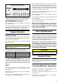 4
4
-
 5
5
-
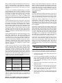 6
6
-
 7
7
-
 8
8
-
 9
9
-
 10
10
-
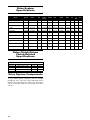 11
11
-
 12
12
-
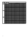 13
13
-
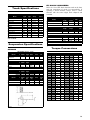 14
14
-
 15
15
-
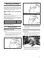 16
16
-
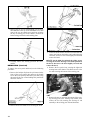 17
17
-
 18
18
-
 19
19
-
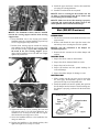 20
20
-
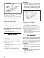 21
21
-
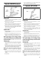 22
22
-
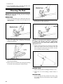 23
23
-
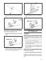 24
24
-
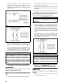 25
25
-
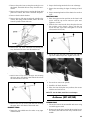 26
26
-
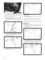 27
27
-
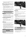 28
28
-
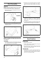 29
29
-
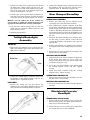 30
30
-
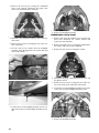 31
31
-
 32
32
-
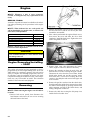 33
33
-
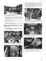 34
34
-
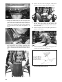 35
35
-
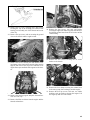 36
36
-
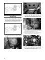 37
37
-
 38
38
-
 39
39
-
 40
40
-
 41
41
-
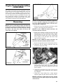 42
42
-
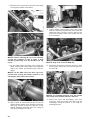 43
43
-
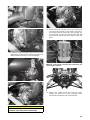 44
44
-
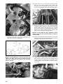 45
45
-
 46
46
-
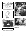 47
47
-
 48
48
-
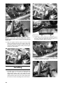 49
49
-
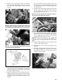 50
50
-
 51
51
-
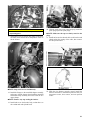 52
52
-
 53
53
-
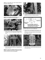 54
54
-
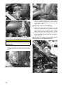 55
55
-
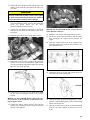 56
56
-
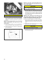 57
57
-
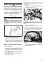 58
58
-
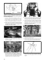 59
59
-
 60
60
-
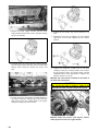 61
61
-
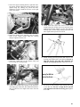 62
62
-
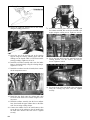 63
63
-
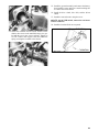 64
64
-
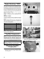 65
65
-
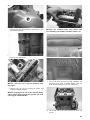 66
66
-
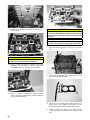 67
67
-
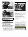 68
68
-
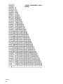 69
69
-
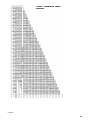 70
70
-
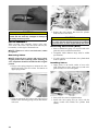 71
71
-
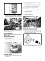 72
72
-
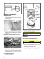 73
73
-
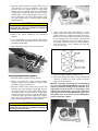 74
74
-
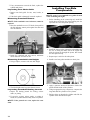 75
75
-
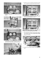 76
76
-
 77
77
-
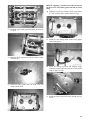 78
78
-
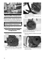 79
79
-
 80
80
-
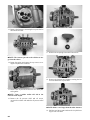 81
81
-
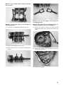 82
82
-
 83
83
-
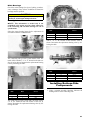 84
84
-
 85
85
-
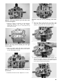 86
86
-
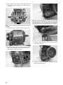 87
87
-
 88
88
-
 89
89
-
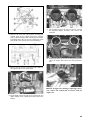 90
90
-
 91
91
-
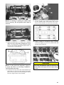 92
92
-
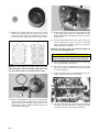 93
93
-
 94
94
-
 95
95
-
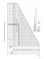 96
96
-
 97
97
-
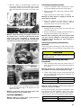 98
98
-
 99
99
-
 100
100
-
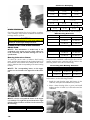 101
101
-
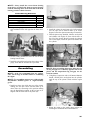 102
102
-
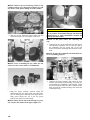 103
103
-
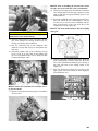 104
104
-
 105
105
-
 106
106
-
 107
107
-
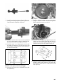 108
108
-
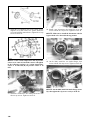 109
109
-
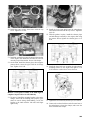 110
110
-
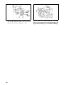 111
111
-
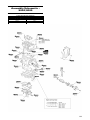 112
112
-
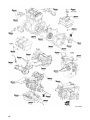 113
113
-
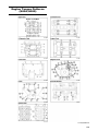 114
114
-
 115
115
-
 116
116
-
 117
117
-
 118
118
-
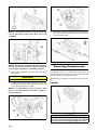 119
119
-
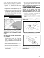 120
120
-
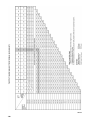 121
121
-
 122
122
-
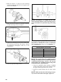 123
123
-
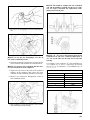 124
124
-
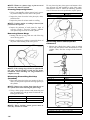 125
125
-
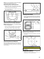 126
126
-
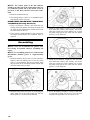 127
127
-
 128
128
-
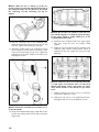 129
129
-
 130
130
-
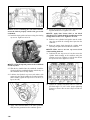 131
131
-
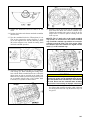 132
132
-
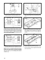 133
133
-
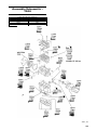 134
134
-
 135
135
-
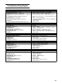 136
136
-
 137
137
-
 138
138
-
 139
139
-
 140
140
-
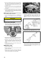 141
141
-
 142
142
-
 143
143
-
 144
144
-
 145
145
-
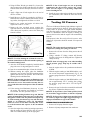 146
146
-
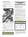 147
147
-
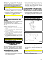 148
148
-
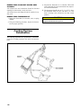 149
149
-
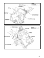 150
150
-
 151
151
-
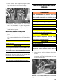 152
152
-
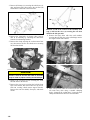 153
153
-
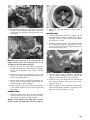 154
154
-
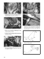 155
155
-
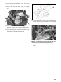 156
156
-
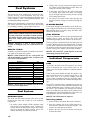 157
157
-
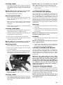 158
158
-
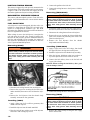 159
159
-
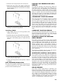 160
160
-
 161
161
-
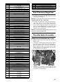 162
162
-
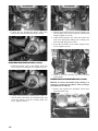 163
163
-
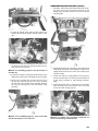 164
164
-
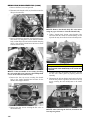 165
165
-
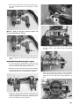 166
166
-
 167
167
-
 168
168
-
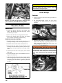 169
169
-
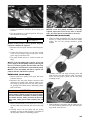 170
170
-
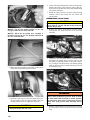 171
171
-
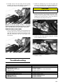 172
172
-
 173
173
-
 174
174
-
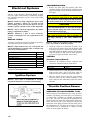 175
175
-
 176
176
-
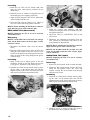 177
177
-
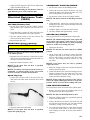 178
178
-
 179
179
-
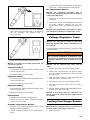 180
180
-
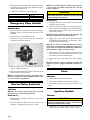 181
181
-
 182
182
-
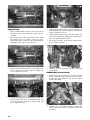 183
183
-
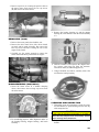 184
184
-
 185
185
-
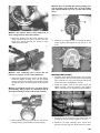 186
186
-
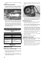 187
187
-
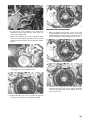 188
188
-
 189
189
-
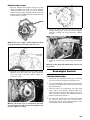 190
190
-
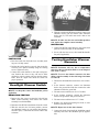 191
191
-
 192
192
-
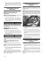 193
193
-
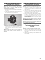 194
194
-
 195
195
-
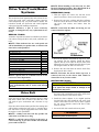 196
196
-
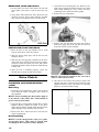 197
197
-
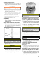 198
198
-
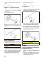 199
199
-
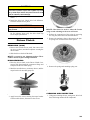 200
200
-
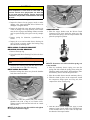 201
201
-
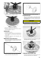 202
202
-
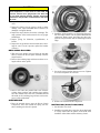 203
203
-
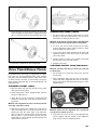 204
204
-
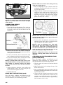 205
205
-
 206
206
-
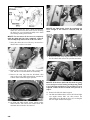 207
207
-
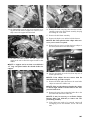 208
208
-
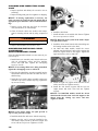 209
209
-
 210
210
-
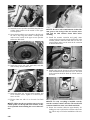 211
211
-
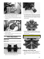 212
212
-
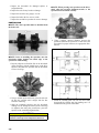 213
213
-
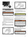 214
214
-
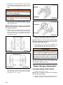 215
215
-
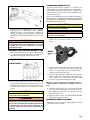 216
216
-
 217
217
-
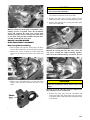 218
218
-
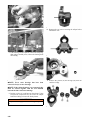 219
219
-
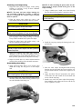 220
220
-
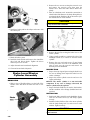 221
221
-
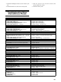 222
222
-
 223
223
-
 224
224
-
 225
225
-
 226
226
-
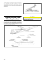 227
227
-
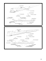 228
228
-
 229
229
-
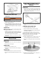 230
230
-
 231
231
-
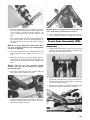 232
232
-
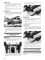 233
233
-
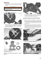 234
234
-
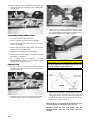 235
235
-
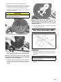 236
236
-
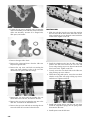 237
237
-
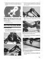 238
238
-
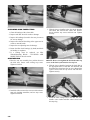 239
239
-
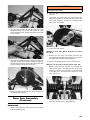 240
240
-
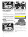 241
241
-
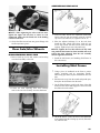 242
242
-
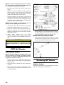 243
243
-
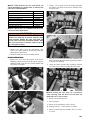 244
244
-
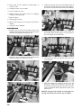 245
245
-
 246
246
-
 247
247
-
 248
248


Arctic Cat Pantera 3000 User manual
- Category
- Engine
- Type
- User manual
Ask a question and I''ll find the answer in the document
Finding information in a document is now easier with AI
Related papers
-
Arctic Cat Jaguar Z1 User manual
-
-
-
-
-
-
-
-
-
Other documents
-
SCANGRIP MAG PRO Multipurpose and Rechargeable LED Work Light User guide
-
Ridetech 11349572 Operating instructions
-
-
-
-
-
-
-
Lennox iComfort Thermostat Mag-Mount (12X99) Installation guide
-
 Teraflex 4627400 Installation guide
