Page is loading ...

2016
OPERATOR MANUAL
PANTERA
®
7000 XT
™
LTD/
BEARCAT
®
/LYNX
®
2000/3000/7000
www.arcticcat.com

Limited Warranty
Arctic Cat Inc. (hereinafter referred to as Arctic Cat) extends a limited warranty as described below on
each new Arctic Cat Snowmobile it assembles and on each genuine Arctic Cat Snowmobile part and
accessory assembled and sold by an authorized Arctic Cat Snowmobile dealer. The limited warranty on
an Arctic Cat Snowmobile is extended to the original retail purchaser for the time periods described
below; however, the balance of the remaining warranty may be transferred to another party unless the
purchase is for commercial use (see below). Warranty coverage is only available in the country in which
the original retail purchase occurs to the original retail purchaser resident in that country or to a transferee
resident in that country of the balance of the remaining warranty.
Arctic Cat warrants only the products it assembles and/or sells and does not warrant that other products
will function properly when used with an Arctic Cat Snowmobile or will not damage the Arctic Cat
Snowmobile. Arctic Cat does not assume any liability for incidental or consequential damages.
Arctic Cat will repair or replace, at its option, free of charge (including any related labor charges), any parts
that are found to be warrantable in material or workmanship. This repair work MUST be done by an
authorized Arctic Cat Snowmobile dealer. No transportation charges, rental charges, or inconvenience costs
will be paid by Arctic Cat. The warranty is validated upon examination of said parts by Arctic Cat or an
authorized Arctic Cat Snowmobile dealer. Arctic Cat reserves the right to inspect such parts at its factory for
final determination if warranty should apply.
The warranty periods are as follows:
1. For snowmobiles used for recreational purposes:
—If purchased between May 1 and November 30, warranty expires ONE (1) YEAR from December 1
of the current year.
—If purchased between December 1 and April 30, ONE (1) YEAR from the date of sale.
2. For snowmobiles used for commercial purposes (including rental operations), ONE (1) YEAR from
the date of invoice and/or 5000 MILES whichever comes first (non-transferable).
3. THIRTY (30) DAYS from date of sale of snowmobile on Arctic Cat supplied batteries.
Exclusions to this warranty include normal wear, abuse (i.e. a track run on marginal snow conditions
without proper lubrication or additional idler wheels), and the following parts:
Fuel Filter Light Bulbs Windshield Drive Belt Torn or Punctured Upholstery
Wear Bars Brake Pads Spark Plugs Drive Clutch/Driven Pulley Wear Parts
Wear Strips Shock Absorber(s)*
* Limited to one (1) year of “normal” riding conditions - replace for defective or leaking shock, corroded or pitted shaft, peeling
chrome.
NOTE: Snowmobiles that are factory equipped with Fox, Elka, or JRI shocks and experience a shock
failure of workmanship or material within the factory warranty period must not be tampered with. Only the
air pressure valve (p/n 2603-511 - Fox shocks only) is serviceable during the warranty period. Any other
tampering with the shock will void warranty.
The following will VOID Arctic Cat’s warranty:
1. Failure to perform the proper break-in procedure and all related maintenance, storage procedures (if
stored for extended periods), and/or service as recommended in the Operator’s Manual.
2. Repairs and/or adjustments by anyone other than an authorized Arctic Cat Snowmobile dealer.
3. Use of an improper fuel mixture ratio.
4. Use of improper carburetor jets.
5. Use of improper gasoline, lubricating oils, or spark plugs.
6. An accident or subjecting the snowmobile to misuse, abuse, or negligent operation.
7. Any modification, addition, or removal of parts unless instructed to do so by Arctic Cat.
8. Use of the snowmobile in any way for racing purposes.
9. Removal of the engine for use in another vehicle.
10. Removal or mutilation of the Vehicle Identification Number or Engine Serial Number.
11. Use of parts not sold or approved by Arctic Cat.
12. Track and tunnel damage resulting from either ice stud or hooker plate installation.
13. Damage due to improper transportation.
Arctic Cat shall not be responsible for and this limited warranty excludes recovery of economic, punitive,
consequential and incidental damages, lost profits, and loss of use. Some states or provinces do not allow
the exclusion or limitation of incidental or consequential damages, so the above limitation may not apply
to you. Arctic Cat’s aggregate liability may not exceed the price of the product. The law of the State of
Minnesota shall apply to all claims or disputes, exclusive of its conflicts of law provisions.
IMPLIED WARRANTY EXCLUSION AND DISCLAIMER
To the fullest extent permitted by law, Arctic Cat excludes and disclaims all implied warranties of
merchantability and fitness for a particular purpose.
If you are not satisfied with warranty service or repairs, you should contact Arctic Cat at (U.S.) 1-218-681-
9851 or (Canada) 1-204-982-1656.

Table of Contents
Limited Warranty .....................Inside Front Cover
Foreword ............................................................ 1
Declaration of Conformity................................... 2
Snowmobile Safety Rules ..................................3
General Information ......................................4-21
Control Locations .............................................. 4
Snowmobile Identification.................................. 5
Gasoline-Oil....................................................... 5
Engine Break-In................................................. 6
Drive Belt Break-In ............................................ 7
Speedometer/Tachometer/Digital Gauge .......... 7
Diagnostic Codes ............................................ 11
Handlebar Tilt .................................................. 13
Exhaust System .............................................. 14
Air-Intake Silencer ........................................... 14
Air-Intake Filter (7000)..................................... 14
Cooling System (3000/7000)........................... 14
Battery ............................................................. 14
Drive Clutch and Driven Clutch ....................... 16
Drive Clutch/Driven Clutch Alignment ............. 16
Fuel Pump ....................................................... 16
Shock Absorbers ............................................. 16
Standard-Lug Track ......................................... 16
Track Studs...................................................... 16
Reverse Operation .......................................... 17
Adjustable/Movable Backrest .......................... 19
Removable Rear Seat ..................................... 19
Removable Light Bar (Bearcat XT GS) ........... 20
Towing ............................................................. 21
Operating Instructions ......................................22
Pre-Start.......................................................... 22
Starting and Stopping Engine ......................... 23
Braking ............................................................ 23
Emergency Stopping ....................................... 24
Engine Heater (Pantera 7000 XT LTD/Bearcat
7000 GS) ....................................................... 25
Throttle/Ignition Monitor Switch ....................... 25
Varying Altitude Operation............................... 26
Lubrication .................................................. 28-32
Gear Case (2000)............................................ 28
Chain Case (3000) ..........................................29
Transmission (7000) ........................................30
Front Suspension (2000) .................................31
Rear Suspension .............................................31
Maintenance ............................................... 32-62
Periodic Maintenance Checklist....................... 32
Fuel System.....................................................33
Checking Engine Oil Level...............................34
Changing Engine Oil/Filter...............................35
Coolant Level...................................................37
Adjusting/Calibrating Carburetors (2000) ........ 38
Spark Plugs .....................................................41
Valve Clearance............................................... 42
Battery ............................................................. 42
Fuses............................................................... 44
Brake System ..................................................45
Burnishing Brake Pads ....................................48
Drive Belt .........................................................48
Checking/Adjusting Deflection.........................50
Track Tension...................................................51
Track Alignment ...............................................52
Suspension......................................................53
Lights ...............................................................55
Ski Wear Bars..................................................60
Adjusting Ski Stance........................................60
Rail Wear Strips...............................................61
Preparation for Storage ....................................62
Preparation after Storage .................................63
U.S. EPA Emission Control Statement/Warranty
Coverage (U.S. Only) ....................................64
Change of Address, Ownership, or Warranty
Transfer .........................................................65
Warranty Procedure/Owner
Responsibility .......................Inside Back Cover

Reference Information
Write the appropriate information for your Arctic Cat Snowmobile in the spaces
below.
Always use these numbers when referring to your snowmobile.
Model: _________________________________________________
Date of Purchase: ________________________________________
Vehicle Identification Number: _______________________________
Engine Serial Number: _____________________________________
Your Arctic Cat Dealer: ___________________________________
Address: _______________________________________________
Phone: _________________________________________________
! WARNING
A snowmobile is a very high performance vehicle. Because it does accelerate
rapidly and is capable of very high speeds, it should not be operated by a nov-
ice or an inexperienced operator. Never accelerate rapidly or drive at high speed
beyond the limits of visibility or without being totally familiar with the terrain
and what lies in front of you. Obey speed limits and never operate at speeds that
do not allow adequate maneuvering and stopping distances. Read and study
the entire Operator’s Manual and Safety Handbook.
Failure to follow this warning could result in personal injury to yourself or others.
Personal Injury
• To avoid injury to yourself and others, NEVER operate the snowmobile without
first reading and understanding this manual and the Snowmobile Safety Hand-
book; then follow the instructions and heed the warnings given.
• USE COMMON SENSE.
• DON’T DRINK and DRIVE.
• STAY IN CONTROL at ALL TIMES.
• TELL YOUR FRIENDS. If you see a friend operating a snowmobile recklessly, at
excessive speeds, while intoxicated, or in other unsafe ways, don’t wait until it is
too late to warn of the consequences of snowmobile misuse. Such conduct
endangers everyone. TAKE AN ACTIVE ROLE IN THE SAFETY OF YOUR-
SELF AND OTHERS.
Parts and Accessories
When in need of replacement parts, oil, or accessories for your Arctic Cat Snowmo-
bile, be sure to only use GENUINE ARCTIC CAT PARTS, OIL, AND ACCESSO-
RIES. Only genuine Arctic Cat parts, oil, and accessories are engineered to meet the
standards and requirements of your Arctic Cat Snowmobile. For a complete list of
accessories, refer to the current Arctic Cat Accessory Catalog. To aid in service and
maintenance procedures on these snowmobiles, an Illustrated Parts Manual and a
Service Manual are available through your local Arctic Cat Snowmobile dealer.

1
Foreword
Congratulations! You have chosen a quality Arctic Cat Snowmobile designed and
assembled to give dependable service. Be sure, as the owner/operator of an Arctic
Cat Snowmobile, to become thoroughly familiar with its basic operation, mainte-
nance, and off-season storage procedures. Read this manual and the accompanying
Snowmobile Safety Handbook before operating the snowmobile to learn safe and
proper use of your new Arctic Cat Snowmobile. Always operate the snowmobile
within your level of skill and current terrain conditions.
The Operator’s Manual, Snowmobile Safety Handbook, and Snowmobile Decals
display the words Warning, Caution, and Note to emphasize important information.
The symbol ! WARNING identifies personal safety-related information. Be
sure to follow the directive because it deals with the possibility of serious personal
injury or even death. A CAUTION identifies unsafe practices which may result
in snowmobile-related damage. Follow the directive because it deals with the possi-
bility of damaging part or parts of the snowmobile. The symbol
NOTE: identi-
fies supplementary information worthy of particular attention.
This manual covers operator-related maintenance, operating instructions, and off-
season storage instructions. If major repair or service is ever required, contact an
authorized Arctic Cat Snowmobile dealer for professional service.
At the time of publication, all information and illustrations were technically cor-
rect. Some illustrations used in this manual are used for clarity purposes only and
are not designed to depict actual conditions. Because Arctic Cat Inc. constantly
refines and improves its products, no retroactive obligation is incurred.
This Operator’s Manual should be considered a permanent part of the snowmobile
and must remain with the snowmobile at the time of resale. If the snowmobile
changes ownership more than once, contact Arctic Cat Inc., Service Department,
P.O. Box 810, Thief River Falls, MN 56701, for proper registration information.
This manual was prepared by the Product Service and Warranty Department of
Arctic Cat Inc.
Every Arctic Cat Snowmobile meets or exceeds the standards of the Snowmobile
Safety and Certification Committee and displays the SSCC decal. Arctic Cat Inc.
endorses and encourages the safe use of all snowmobiles. Always wear a helmet
and eye protection. Drive with caution, observe all state and local regulations, and
respect the rights of others. ISMA members like Arctic Cat do their part to improve
trails, sponsor events, and generally support the sport of snowmobiling. As a mem-
ber of the National Snowmobile Foundation, Arctic Cat Inc. promotes snowmobil-
ing through education, charity, and research programs.
© 2015 Arctic Cat Inc.
Printed in U.S.A.

2
Declaration of Conformity
I, the undersigned, hereby declare that the equipment specified above conforms to the
directive(s) and standard(s) as specified.
Brad Darling
Vice President/General Manager - Snowmobile Division
Application of council directives:
Issued by European Commission.
EMC Directive 2004/108/EC
EC Machinery Directive 2006/42/EC
Type of Equipment: Snowmobile
Model Numbers:
Brand Name: Arctic Cat
S2016BCDFCOSL S2016BCDWTUSL S2016BCUWTRUL S2016PTTTOOSB
S2016BCDFCUSL S2016BCTLTUSL S2016BCUWTRUR S2016PTTTORUB
S2016BCDWEOSB S2016BCUWGOSO S2016BCUWTUSL S2016PTTTOUSB
S2016BCDWERUB S2016BCUWGRUO S2016BCUWTUSR S2016PTUWLOSB
S2016BCDWEUSB S2016BCUWGUSO S2016LXDFCUSB S2016PTUWLRUB
S2016BCDWTOSL S2016BCUWTOSL S2016LXDLTUSB S2016PTUWLUSB
S2016BCDWTRUL S2016BCUWTOSR
Standards to which conformity is declared:
EMC: EN 55012, EN 61000-6-2 MACHINERY: EN 12100:2010
Manufacturer (if not issuing agent): Arctic Cat Inc.
601 Brooks Ave. S.
Thief River Falls, MN 56701 USA

3
Snowmobile Safety Rules

4
General Information
Control Locations
Shown are the control locations.
Bearcat 7000 XT
XM314A
Pantera 7000 XT LTD
0749-189
Bearcat 7000 XT GS
0749-190

5
Bearcat 3000 LT
0747-616B
Bearcat 2000/Lynx
0744-441
Snowmobile
Identification
The Arctic Cat Snowmobile has two import-
ant identification numbers. The Vehicle
Identification Number (VIN) is stamped
into the tunnel near the right-side footrest.
The Engine Serial Number (ESN) is
stamped into the crankcase of the engine.
These numbers are required by the dealer
to complete warranty claims properly. No
warranty will be allowed by Arctic Cat
Inc. if the engine serial number or VIN is
removed or mutilated in any way.
Always provide the snowmobile name,
VIN, and ESN when contacting an autho-
rized Arctic Cat Snowmobile dealer for
parts, service, accessories, or warranty. If
the complete engine must be replaced,
ask the dealer to notify Arctic Cat for
correct registration information.
Gasoline-Oil
Recommended Gasoline
The recommended gasoline to use in these
snowmobiles is 87 octane regular
unleaded. In many areas, oxygenates are
added to the gasoline. Oxygenated gaso-
lines containing up to 10% ethanol are
acceptable gasolines; however, on the
2000 models whenever using oxygenated
gasolines, the carburetor main jet must be
one size larger than the main jet required
for regular unleaded gasoline. For exam-
ple, if a 220 main jet is recommended for
regular unleaded gasoline, a 230 main jet
must be installed if using an oxygenated
gasoline.
When using ethanol blended gasoline, it is
not necessary to add a gasoline antifreeze
since ethanol will prevent the accumula-
tion of moisture in the fuel system.
CAUTION
Do not use white gas or gasolines
containing methanol.

6
Recommended Engine
Oil
2000
The recommended oil to use in the oil-
injection system is Arctic Cat Formula 50
Injection Oil (p/n 5639-475 - qt) or (p/n
5639-476 - gal.). This oil is specially for-
mulated to be used either as an injection
oil or as a pre-mix oil (for break-in) and
meets all of the lubrication requirements
of the Arctic Cat snowmobile engine.
3000/7000
The recommended oil to use is C-TEC4
Synthetic Oil (p/n 6639-524 - qt) or (p/n
6639-525 - gal.).
After the engine break-in period, the
engine oil should be changed every 2500
miles and before prolonged storage.
Filling Gas Tank
Since gasoline expands as its temperature
increases, the gas tank must be filled to
its rated capacity only. Expansion room
must be maintained in the tank particu-
larly if the tank is filled with cold gaso-
line and then moved to a warm area.
Also, if the snowmobile is to remain on a
trailer after filling the gas tank, the bed of
the trailer must be maintained level to
prevent gasoline from draining out
through the gas tank vent hose.
Engine Break-In
2000
Before mixing gasoline and oil, make sure
the oil is at room temperature (20° C/68°
F). Use a U.L. approved 22.7 l (6 U.S. gal.)
gasoline container for mixing the gasoline
and oil. To properly mix the fuel at a 100:1
ratio, use the following procedure:
1. Pour gasoline into the gasoline con-
tainer until approximately half full.
2. Pour 236 ml (8 fl oz) of the recom-
mended 2-cycle oil into the gasoline
container.
3. Install cap on gasoline container and
shake the mixture vigorously.
4. Fill the gasoline container with gaso-
line; then cap the gasoline container
and shake the mixture vigorously.
5. Using a fine-mesh screened funnel,
pour the fuel mixture from the gaso-
line container into the snowmobile
gas tank.
3000
This engine does not require any pre-
mixed fuel during the break-in period.
To ensure trouble-free operation, careful
adherence to the following break-in
guidelines will be beneficial.
* With occasional full-throttle operation
CAUTION
Any oil used in place of the recom-
mended oil could cause serious
engine damage.
! WARNING
Always fill the gas tank in a well-venti-
lated area. Never add gasoline to the
snowmobile gas tank near any open
flames or with the engine running. DO
NOT SMOKE while filling the gas tank.
CAUTION
Never mix oil and gasoline in the
snowmobile gas tank.
! WARNING
Always fill the gas tank in a well-ven-
tilated area. Never add gasoline to the
snowmobile gas tank near any open
flames or with the engine running. DO
NOT SMOKE while mixing fuel or fill-
ing the gas tank.
CAUTION
DO NOT use premixed fuel in the
snowmobile gas tank. Engine dam-
age will occur.
0-200 miles 1/2 Throttle (30 MPH-max)
200-400 miles 1/2-3/4 Throttle
400-600 miles 1/2-3/4 Throttle*

7
To ensure proper engine break-in, Arctic
Cat recommends that the engine oil and
filter be changed after 500 miles. This
service is at the discretion and expense of
the snowmobile owner.
7000
Premixing fuel and oil during the break
in period is not required. There is never a
more important period in the life of the
engine than the first 300 miles.
Since the engine is brand new, do not put
an excessive load on it for the first 300
miles. The various parts in the engine
wear and polish themselves to the correct
operating clearances. During this period,
prolonged full throttle operation or any
condition that might result in engine
overheating must be avoided.
Operating your snowmobile for the first
time: Start the engine and let it idle for 15
minutes.
0-160 km (0–100 miles): Avoid pro-
longed operation above 6000 RPM.
160-500 km (100–300 miles): Avoid pro-
longed operation above 8000 RPM.
500 km (300 miles) and beyond: The snow-
mobile can now be operated normally.
NOTE: After 500 miles of opera-
tion, the engine oil must be changed
and the oil filter replaced. If any
engine trouble should occur during
the engine break-in period, immedi-
ately have a Arctic Cat dealer check
the snowmobile.
Drive Belt Break-In
Drive belts require a break-in period of
25 miles. Drive the snowmobile for 25
miles at 3/4 throttle or less. By revving
the engine up and down (but not exceed-
ing 60 mph), the exposed cord on the side
of a new belt will be worn down. This
will allow the drive belt to gain its opti-
mum flexibility and will extend drive belt
life.
NOTE: Before starting the snowmo-
bile in extremely cold temperatures, the
drive belt should be removed and
warmed up to room temperature. Once
the drive belt is at room temperature,
install the drive belt.
Speedometer/
Tachometer/Digital
Gauge
Standard Gauge (2000)
Certain models are equipped with a stan-
dard gauge combination speedometer/
tachometer. Indicator icons are incorpo-
rated within the speedometer/tachome-
ter. Also incorporated into the
speedometer/tachometer is a digital read-
out screen.
FZ003C
RPM/MPH (kph)
By pushing the left button once, the RPM
and MPH will be displayed (one on the
readout screen and one with the needle).
By pushing the button once again, the
functions will be reversed.
By pushing the left button (with speed
being displayed) for more than two sec-
onds, the display will change between
standard mph or metric kph. Release the
button when desired display appears.
With RPM displayed on the readout screen
by pushing and holding the left button, max-
imum RPM will be displayed on the readout
screen. The maximum RPM readout will
reset when the right button is pushed (while
maximum RPM is displayed).
CAUTION
Never run the engine with the drive
belt removed. Excessive revving of
the engine could result in serious
engine damage and drive clutch fail-
ure.

8
Odometer/Trip-Meter (1)/
Trip-Meter (2)/Hour-
Meter/Clock
NOTE: The clock is available on
electric start models only.
By pushing the right button, the readout
screen will display odometer, trip-meter
(1), trip-meter (2), hour-meter, and clock.
To reset the trip meter with the trip meter
displayed, push and hold the right button
until the display is cleared. The hour-
meter readout will not reset.
Clock (Electric Start)
With the clock selected on the readout
screen by pushing and holding the right but-
ton for two seconds, the option of selecting
the 12-hour or 24-hour clock is available.
Push the left button for 12-hour display;
push the right button for 24-hour display. At
this point, the hours and minutes will begin
to flash. Push the left button to change the
hour display; push the right button to change
the minute display (either tap the buttons for
individual number display or push and hold
the buttons for rapid number display).
NOTE: During clock setting if nei-
ther button (left, right) is pushed
within a 5-second time period, the
clock-setting mode will be exited
with changes saved.
A. Low Oil Warning Icon
This icon is designed to alert the snowmo-
bile operator when the oil in the oil injec-
tion reservoir gets below a prescribed
level; however, it is highly recommended
that a visual verification of the oil level in
the reservoir be done prior to operating the
snowmobile. Once the Low Oil Warning
Icon illuminates during operation of the
snowmobile, the operator must periodi-
cally monitor the level of oil in the reser-
voir and must fill the reservoir the next
time gasoline is added to the gas tank.
The “alert level” of the Low Oil Warning
Icon is approximately equal to 1 tankful of
gasoline under normal operating condi-
tions.
B. Coolant Temperature
Warning Icon
NOTE: When cold-starting the
engine, the coolant temperature
warning icon will illuminate, the read-
out screen will display TEMP, and
engine RPM limit will be below drive
system engagement speed.
When the engine reaches proper operat-
ing temperature, the coolant temperature
warning icon and TEMP display will
cease to flash.
If the coolant temperature rises too far
above proper operating temperature, the
coolant temperature warning icon will
flash a warning (alert) and the engine will
“surge” to alert the operator. If the cool-
ant temperature rises to a critical point
above proper operating temperature, the
coolant temperature warning icon will
cease flashing and will remain constantly
illuminated.
NOTE: If the coolant temperature
icon is constantly on, the engine will
shut off if vehicle speed is reduced
to 1.5 kph (0.9 MPH) or slower.
C. Low Fuel Indicator
The indicator illuminates whenever the
gas in the gas tank is low.
D. Fuel Level Display
This bar display shows the approximate
amount of gas remaining in the gas tank.
CAUTION
At this point, take precautionary mea-
sures such as changing to loose
snow terrain, shutting the engine off
(allowing the engine to cool down),
and checking coolant level. If unable
to either determine or remedy the
problem, take the snowmobile to an
authorized Arctic Cat Snowmobile
dealer for service. If not under war-
ranty, this service is at the discretion
and expense of the snowmobile
owner.

9
E. Service Icon
On electric start models, the icon should
illuminate each time the key is turned to
RUN or START, and it should go out
when the engine starts. If the icon stays
illuminated (on electric start models) or it
illuminates while the engine is running,
the system is receiving input that is out-
side of its established parameters. If the
icon illuminates indicating an error, take
the snowmobile to an authorized Arctic
Cat Snowmobile dealer for service. If not
under warranty, this service is at the dis-
cretion and expense of the snowmobile
owner.
F. High Beam Indicator
The indicator is on whenever the high
beam mode is selected by the headlight
switch.
Standard Gauge (3000/
7000)
XM248A
1. Left Button - Shifts top display
through speedometer, RPM, and
clock.
2. Middle Button - Shifts middle dis-
play through speedometer, RPM,
clock, odometer, trip 1, trip 2, and
engine hours.
3. Right Button - Shifts bottom display
through coolant temperature, bat-
tery voltage, and fuel level.
4. Speedometer/Tachometer Display -
Indicates approximate vehicle speed
in MPH or KM/H when speedome-
ter function is selected, RPM when
tachometer function is selected.
Press the Left Button to change
which parameter is being displayed.
With speedometer selected, press
and hold the Left Button to shift
between standard (MPH/miles/Fahr-
enheit) and metric (km/h/kilometers/
Celsius).
5. Engine Hour Meter/Odometer/Trip
Meter/Speedometer/Tachometer/
Clock Display - Displays engine
hours, odometer, trip meter, speed-
ometer, tachometer, or clock. Press
the Middle Button to change which
parameter is being displayed. The
Engine Hour Meter and Odometer
cannot be reset. To reset the trip
meter, select the Trip Meter; then
press and hold the Middle Button
until the trip meter display reads 0.
With the clock mode selected, press
and hold the Left Button to set the
clock. The option of selecting the
12-hour or 24-hour clock is avail-
able; press the Left Button to alter-
nate between the two modes. Next,
press the Middle Button to set the
clock. Press the Left or Right to set
the hours; then press the Middle
Button to set the minutes. Press the
Left or Right Button to set the min-
utes. When the proper time has been
set, press the Middle Button to
return to the main gauge display.
6. Coolant Temperature/Battery Volt-
age/Fuel Level Display - Displays
coolant temperature, battery voltage,
and fuel quantity. Press the Right
Button to change which parameter is
being displayed. Press and hold the
Right Button to see the actual values
associated with the mode selected.
7. Gear Position Indicator - Indicates
what gear the transmission is in.
8. Coolant Temperature Indicator -
When the snowmobile is started, this
indicator will flash and LOW TEMP
will be displayed until the engine
reaches operating temperature.

10
If the coolant temperature rises too
far above proper operating tempera-
ture, the indicator will flash a warn-
ing (alert) and the engine will
“surge” to alert the operator. If the
coolant temperature rises to a critical
point above proper operating tem-
perature, the indicator will cease
flashing and will remain constantly
illuminated.
NOTE: If the indicator is constantly
on, the engine will shut off if vehicle
speed is reduced to 1.5 km-h (0.9
MPH) or slower.
9. High Beam Indicator - The indicator
is on whenever the high beam mode
is selected by the headlight switch.
10. Oil Pressure Indicator - The indicator
relates to engine oil pressure, not the
oil level; however, if the oil level is
low, it may affect oil pressure. If oil
pressure is lost, check the oil level. If
the indicator does not go out or if the
engine does not start, take the snowmo-
bile to an authorized Arctic Cat Snow-
mobile dealer. If not under warranty,
this service is at the discretion and
expense of the snowmobile owner.
11. Fuel Level Indicator - The indicator
will display whenever gas is low in
the fuel tank.
Deluxe Digital Gauge
(Pantera 7000 XT LTD)
CWI-051A
A. Coolant Temperature
Indicator
The indicator and LOW TEMP display will
cease to flash when the engine reaches
proper operating temperature.
If the coolant temperature rises too far
above proper operating temperature, the
indicator will flash a warning (alert) and
the engine will “surge” to alert the opera-
tor. If the coolant temperature rises to a
critical point above proper operating tem-
perature, the indicator will cease flashing
and will remain constantly illuminated.
NOTE: If the indicator is constantly
on, the engine will shut off if vehicle
speed is reduced to 1.5 km-h (0.9
MPH) or slower.
B. High Beam Indicator
The indicator is on whenever the high
beam mode is selected by the headlight
switch.
C. Oil Pressure
The indicator relates to engine oil pres-
sure, not the oil level; however, if the oil
level is low, it may affect oil pressure. If
oil pressure is lost, check the oil level.
CAUTION
If the indicator is illuminated, stop the
engine immediately and allow it to cool
down. If unable to either determine or
remedy the problem, take the snowmo-
bile to an authorized Arctic Cat Snow-
mobile dealer for service. If not under
warranty, this service is at the discretion
and expense of the snowmobile owner.
CAUTION
If the indicator is illuminated, stop the
engine immediately and allow it to cool
down. If unable to either determine or
remedy the problem, take the snowmo-
bile to an authorized Arctic Cat Snow-
mobile dealer for service. If not under
warranty, this service is at the discre-
tion and expense of the snowmobile
owner.

11
If the indicator does not go out or if the
engine does not start, take the snowmo-
bile to an authorized Arctic Cat Snowmo-
bile dealer. If not under warranty, this
service is at the discretion and expense of
the snowmobile owner.
D. Low Fuel Indicator
The indicator illuminates whenever the
gas in the gas tank is low.
E. Coolant Temperature/
Battery Voltage/Intake Air
Temperature Display
This bar display shows coolant tempera-
ture, battery voltage, and intake air tem-
perature. Press the Lower Left Button to
change which parameter is being dis-
played. Press and hold the Lower Left
Button to see the actual values associated
with the mode selected.
F. Fuel Level Display
This bar display shows the approximate
amount of gas remaining in the gas tank.
G. RPM/Speed/Clock/
Altimeter
Press the Upper Left Button to cycle the
left screen between RPM and speed.
NOTE: When RPM is displayed on
the left screen, the right screen will
display speed, clock, or altimeter.
When speed is displayed on the left
screen, the right screen will display
RPM, clock or altimeter.
Press the Upper Right Button to cycle the
right screen between speed, RPM, clock,
and altimeter.
Press and hold the Upper Button on the
speed-side of the gauge to shift between
standard (MPH/miles/Fahrenheit) and
metric (km/h/kilometers/Celsius).
Press and hold the Upper Button on the
RPM-side to view maximum RPM. This
value is reset each time the ignition key is
turned off.
With the clock mode selected by pressing
the Upper Right Button, press and hold the
Upper Right Button to set the clock. The
option of selecting the 12-hour or 24-hour
clock is available; press the either Left But-
ton to alternate between the two modes.
Next, press the Lower Right Button to set
the clock. Press either Left Button to set the
hours; then press the Lower Right Button to
set the minutes. Press either Left Button to
set the minutes. When the proper time has
been set, press the Lower Right Button to
return to the main gauge display.
With the altimeter mode selected by
pressing the Upper Right Button, press
and hold the Upper Right Button to set
the current altitude by using either Left
Button. When the proper altitude has
been set, press the Lower Right Button to
return to the main gauge display.
H. Engine Hour Meter/
Odometer/Trip Meter/
Clock
This display shows engine hours, odome-
ter, trip meter, or clock. Press the Lower
Right Button to change which parameter
is being displayed. The Engine Hour
Meter and Odometer cannot be reset. To
reset the trip meter, select the Trip Meter;
then press and hold the Lower Right But-
ton until the trip meter display reads 0.
NOTE: The clock can only be dis-
played in this position if it is not
already being displayed in the main
right screen. To set the clock when
the clock is in this position, press
and hold the Lower Right Button;
then use the procedure found in G.
Diagnostic Codes
Diagnostic codes are activated by the
ECM and may be displayed on the read-
out screen for a number of reasons. If a
code is displayed while the engine is run-
ning, the ECM is receiving input that is
outside of its established parameters.
If a code has been activated, take the snow-
mobile to an authorized Arctic Cat Snow-
mobile dealer for service. If not under
warranty, this service is at the discretion
and expense of the snowmobile owner.

12
3000
Code Trouble
P0016 Crankshaft Position -
Camshaft Position Correlation
P0030 O2 Heater Control Circuit
P0031 O2 Heater Control Circuit Low
P0032 O2 Heater Control Circuit High
P0107 Manifold Absolute Pressure
Circuit Low
P0108 Manifold Absolute Pressure
Circuit High
P0112 Intake Air Temperature Sensor
Circuit Low
P0113 Intake Air Temperature Sensor
Circuit High
P0114 Intake Air Temperature Sensor
Circuit Intermittent
P0117 Engine Coolant Temperature Sensor 1
Circuit Low
P0118 Engine Coolant Temperature Sensor 1
Circuit High
P0119 Engine Coolant Temperature Sensor 1
Circuit Intermittent
P0121 Throttle Position Sensor Circuit
Range Performance
P0122 Throttle Position Sensor Circuit Low
P0123 Throttle Position Sensor Circuit High
P0130 O2 Sensor Circuit
P0131 O2 Sensor Circuit Low Voltage
P0132 O2 Sensor Circuit High Voltage
P0171 System Too Lean
P0172 System Too Rich
P0201 Injector Circuit/Open - Cylinder 1
P0202 Injector Circuit/Open - Cylinder 2
P0261 Cylinder 1 Injector Circuit Low
P0262 Cylinder 1 Injector Circuit High
P0264 Cylinder 2 Injector Circuit Low
P0265 Cylinder 2 Injector Circuit High
P0340 Camshaft Position Sensor “A” Circuit
P0500 Vehicle Speed Sensor “A”
P0508 Idle Air Control System Circuit Low
P0509 Idle Air Control System Circuit High
P0562 System Relay Voltage Low
P0563 System Relay Voltage High
P0642 Sensor Reference Voltage “A”
Circuit Low
P0643 Sensor Reference Voltage “A”
Circuit High
P0780 Shift Error
P1315 Crankshaft Position Out of Sync
P1338 Crankshaft Spike Detected
P1339 Crankshaft Tooth Number
Detection Error
P1685 Main Relay Open Circuit
P1686 Main Relay Circuit Low
P1687 Main Relay Circuit High
P1688 Reverse Relay Open Circuit
P1689 Reverse Relay Circuit Low
P1690 Reverse Relay Circuit High
P1691 Forward Relay Open Circuit
P1692 Forward Relay Circuit Low
P1693 Forward Relay Circuit High
P1694 Headlight Relay Open
P1695 Headlight Relay Low
P1780 Shift Switch Stuck
P2282 Air Leak Between Throttle Body and
Intake Valves
P2300 Ignition Coil “A” Primary Control
Circuit Low
P2301 Ignition Coil “A” Primary Control
Circuit High
P2303 Ignition Coil “B” Primary Control
Circuit Low/Open
P2304 Ignition Coil “B” Primary Control
Circuit High
U1000 Vehicle not registered or invalid PIN
U1001 Vehicle not registered and vehicle lim-
its enabled
U0155 Lost Communication with the Gauge
Code Trouble

13
7000
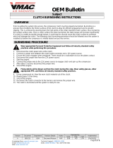
Handlebar Tilt
3000/7000
1. Loosen the four lock nuts securing
the handlebar caps and block to the
steering post.
0745-848B
2. Adjust the handlebar to operator’s
desired tilt; then tighten the cap
screws evenly and securely to 15 ft-
lb. Check steering for maximum
right/left turning capabilities.
NOTE: Do not adjust the handlebar
to a position that allows air to enter
the brake system.
2000
The handlebar can be adjusted to the
operator’s preference. To adjust the han-
dlebar, use the following procedure:
1. Loosen the four cap screws and lock
nuts securing the handlebar caps to the
riser and the riser to the steering post.
Code Trouble
P0031 O2 Heater Control Circuit Low
P0032 O2 Heater Control Circuit High
P0107 Manifold absolute pressure circuit low
P0108 Manifold absolute pressure circuit high
P0112 Intake air temp sensor circuit low
P0113 Intake air temp sensor circuit high
P0115 Engine coolant temp sensor 1 circuit
P0117 Engine coolant temp sensor 1 circuit
low
P0118 Engine coolant temp sensor 1 circuit
high
P0120 Throttle position sensor circuit
P0122 Throttle position sensor circuit low
P0123 Throttle position sensor circuit high
P0130 O2 sensor circuit
P0131 O2 sensor circuit low
P0132 O2 sensor circuit high
P0171 System too lean
P0172 System too rich
P0201 Injector circuit/open - cylinder 1
P0202 Injector circuit/open - cylinder 2
P0203 Injector circuit/open - cylinder 3
P0217 Engine coolant over temp condition
P0261 Cylinder 1 injector circuit low
P0264 Cylinder 2 injector circuit low
P0267 Cylinder 3 injector circuit low
P0508 Idle air control system circuit low
P0509 Idle air control system circuit high
P0511 Idle air control circuit
P0522 Engine oil pressure sensor circuit low
P0523 Engine oil pressure sensor circuit high
P0562 System voltage low
P0563 System voltage high
P0780 Shift Error
P1315 Crankshaft Position out of sync
P1338 Crankshaft spike detected
P1339 Crankshaft tooth not detected
P1685 Main relay open circuit
P1686 Main relay circuit low
P1688 Reverse relay open circuit
P1689 Reverse relay circuit low
P1691 Forward relay open circuit
P1692 Forward relay circuit low
P1694 Headlight relay open circuit
P1695 Headlight relay circuit low
P2228 Barometric pressure sensor A circuit
low
P2229 Barometric pressure sensor A circuit
high
P2300 Ignition coil A primary control circuit
low
P2303 Ignition coil B primary control circuit
low
P2306 Ignition coil C primary control circuit
low
U1000 Vehicle not registered or invalid PIN
U1001 Vehicle not registered and vehicle lim-
its enabled
U0155 Lost communication with the ECM
! WARNING
Tighten cap screws according to speci-
fications to prevent unexpected “move-
ment” of the handlebar during operation
over rough terrain. DO NOT position
handlebar so steering (maximum right/
left turning capabilities) or throttle and
brake controls are affected.

14
744-439A
2. Adjust the handlebar to operator’s
desired position, tighten the cap
screws evenly to 25 ft-lb, and check
steering for maximum right/left
turning capabilities.
NOTE: Do not rotate the handlebar
to a position that allows air to enter
the brake system.
Exhaust System
The exhaust system is designed to reduce
noise and to improve the total perfor-
mance of the engine. If any exhaust sys-
tem component is removed from the
engine and the engine is run, severe
engine damage will result.
Air-Intake Silencer
Used in conjunction with the fuel intake
system is a specially designed air-intake
silencer. The purpose of the silencer is to
quiet the intake of fresh air. Since the fuel
intake system is calibrated with the air-
intake silencer in place, the engine must
never be run with the silencer removed.
Performance will not be improved if the
air-intake silencer is removed. In con-
trast, severe engine damage will occur.
Air-Intake Filter (7000)
The air filter is used in conjunction with
the air-intake system. The purpose of the
filter is to clean the outside air before it is
sucked into the engine. Since the fuel
intake system is calibrated with the filter
in place, the engine must never be run
with the filter removed.
Cooling System (3000/
7000)
These snowmobiles are equipped with a
closed liquid cooling system for engine
cooling. The cooling system should be
inspected daily for leakage and damage.
Also, the coolant level should be checked
daily. If leakage or damage is detected,
take the snowmobile to an authorized
Arctic Cat Snowmobile dealer for ser-
vice. If not under warranty, this service is
at the discretion and expense of the
snowmobile owner.
Battery
It is extremely important that the battery
be maintained at full charge at all times
and that the battery connections be clean
and tight. If charging the battery becomes
necessary, refer to Battery sub-section in
the Maintenance section.
Jump-Starting
NOTE: Arctic Cat does not recom-
mend jump-starting a snowmobile
with a dead battery but rather to
remove the battery, service it, and
correctly charge it; however, in an
emergency, it may be necessary to
jump-start a snowmobile. If so, use
the following procedure to carefully
and safely complete this procedure.
! WARNING
Tighten lock nuts/cap screws accord-
ing to specifications to prevent unex-
pected “movement” of the handlebar
during operation over rough terrain.
DO NOT position the handlebar so
steering (maximum right/left turning
capabilities) or throttle and brake
controls are affected.
CAUTION
These snowmobiles are not designed
to be operated in dusty conditions.
Operating the snowmobile in dusty
conditions will result in severe
engine damage.
CAUTION
Always turn the ignition switch key to
the OFF position when the snowmo-
bile is not being used. Leaving the
ignition switch in the ON position will
result in discharging the battery and
possible damage to the battery.

15
1. On the snowmobile to be jump-started,
slide any terminal boots away.
2. Inspect the battery for any signs of
electrolyte leaks, loose terminals, or
bulging sides. Leaking or bulging
battery cases may indicate a frozen
or shorted battery.
3. Inspect the vehicle to be used for
jump-starting to determine if voltage
and ground polarity are compatible.
The vehicle must have a 12-volt DC,
negative ground electrical system.
4. Move the vehicle to be used for the
jump-start close enough to ensure
the jumper cables easily reach; then
set and lock the brakes, shut off all
electrical accessories, and turn the
ignition switch OFF.
NOTE: Make sure all switches on
the snowmobile to be jump-started
are turned OFF.
5. Disconnect all external accessories
such as cell phones, GPS units, and
radios on both vehicles.
6. Attach one clamp of the positive
(red) cable to the positive (+) termi-
nal (1) of the dead battery (C) being
careful not to touch any metal with
the other clamp; then attach the
other clamp of the positive (red)
cable to the positive (+) terminal (2)
of the good battery (B).
0744-527
NOTE: Some jumper cables may be
the same color but the clamps or ends
will be color-coded red and black.
7. Attach one clamp of the negative
jumper cable (black) to the negative (-)
terminal (3) of good battery (B); then
attach the other clamp of the negative
(black) jumper cable (4) to an unpainted
metal surface (A) on the engine or
frame well away from the dead battery
and fuel system components.
8. Stand well away from the dead bat-
tery and start the vehicle with the
good battery. Allow the vehicle to
run for several minutes applying
some charge to the dead battery.
! WARNING
Improper handling or connecting of a
battery may result in severe injury
including acid burns, electrical burns, or
blindness as a result of an explosion.
Always remove rings and watches.
! WARNING
Any time service is performed on a bat-
tery, the following must be observed:
keep sparks, open flame, cigarettes, or
any other flame away. Always wear
safety glasses. Protect skin and cloth-
ing when handling a battery. When ser-
vicing a battery in an enclosed space,
keep the area well-ventilated.
! WARNING
If any of these conditions exist, DO
NOT attempt to jump-start, boost, or
charge the battery. An explosion
could occur causing serious injury.
CAUTION
Always make sure the electrical sys-
tems are of the same voltage and
ground polarity prior to connecting
jumper cables. If not, severe electrical
damage may occur.
CAUTION
Failure to disconnect electronic
accessories during jump-starting
may cause system damage due to
power spikes.
! WARNING
Never make the final connection to a bat-
tery as a spark could ignite hydrogen
gases causing an explosion of the bat-
tery resulting in acid burns or blindness.

16
9. Start the snowmobile with the dead
battery and allow it to run for several
minutes before disconnecting the
jumper cables.
10. Remove the jumper cables in oppo-
site order of hook-up (4, 3, 2, 1). Be
careful not to short cables against
bare metal.
NOTE: Have the battery and elec-
trical system checked prior to oper-
ating the snowmobile again.
Drive Clutch and Driven
Clutch
The drive clutch and driven clutch do not
require lubrication; therefore, no special
maintenance is required by the snowmo-
bile owner except for periodical cleaning
(see the Periodic Maintenance Checklist
in the Maintenance section).
However, the drive clutch and driven
clutch should be disassembled, cleaned,
and inspected by an authorized Arctic
Cat Snowmobile dealer after every 800
miles of operation or at the end of the
snowmobiling season whichever occurs
first. This service is at the discretion and
expense of the snowmobile owner.
When operating the snowmobile at high
altitudes, it may be necessary to change
certain component parts of the drive
clutch and/or the driven clutch. See an
authorized Arctic Cat Snowmobile dealer
for further information.
Drive Clutch/Driven
Clutch Alignment
The offset between the drive clutch and
driven clutch are set at the factory. Nor-
mally, no adjustment is necessary as long as
neither the drive clutch nor the driven clutch
is removed or disassembled. However, if
premature drive belt wear is experienced or
if the drive belt turns over, the drive clutch/
driven clutch alignment must be checked.
Take the snowmobile to an authorized Arc-
tic Cat Snowmobile dealer for this service.
If not under warranty, this service is at the
discretion and expense of the snowmobile
owner.
Fuel Pump
The fuel pump is designed to provide ade-
quate amount of gas to the injectors at all
throttle settings. If a fuel delivery problem is
suspected, take the snowmobile to an autho-
rized Arctic Cat Snowmobile dealer. If not
under warranty, this service is at the discre-
tion and expense of the snowmobile owner.
Shock Absorbers
Each shock absorber should be visibly
checked weekly for fluid leakage, cracks or
breaks in the lower case, or a bent plunger.
If any one of these conditions is detected,
replacement is necessary. Take the snow-
mobile to an authorized Arctic Cat Snow-
mobile dealer for this service. If not under
warranty, this service is at the discretion and
expense of the snowmobile owner.
Standard-Lug Track
Accelerated wear strip wear caused by
operating on ice or hard-packed snow
conditions is NOT covered under Arctic
Cat Inc. warranty policy.
Track Studs
NOTE: Stud or hooker plate installa-
tion will void track and tunnel warranty.
NOTE: Arctic Cat does not recom-
mend studding a track with a 1.5
inch lug or greater.
CAUTION
DO NOT attempt to service the drive
clutch and driven clutch. The drive
clutch and driven clutch must be ser-
viced by an authorized Arctic Cat
Snowmobile dealer only.
/