Page is loading ...

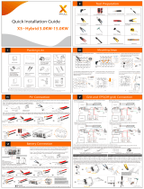
1.0 Product Overview
(1) Grid connector
(2) Backup connector
(3) BAT +
(4) BAT -
(5) ery circuit breaker
(6) PV connectors
(7) PV switch
(8) Wi-Fi port
(9)
(10) LED display
Dimension: W×H×D=483×380×190mm
for SunPower Reserve
(1)
(2)
(3)
(4)
(5)
(6)
(7)
(8)
(9)
(10)
You must protect each inverter with an
individual AC circuit breaker in order to ensure
that the inverter can be disconnected safely
(X2)
(X16) (X1
Grid-CT Grid-CT CablePV-CT PV-CT Cable
)
(X1) (X1) (X1)
(X1)
(X1)
(X1)
(X1)
(X1) (X1)
(X1)
(X1) (X1) (X1)
(X1)(X1) (X2)
Approx. 10-12mm
For “L”and “N”
7-8mm
9-12mm
Approx. 18mm for PE
L
N
PE
(X1)
click
click
7mm
7mm
PV1-F/UL-ZKLA/USE2
PV1-F/UL-ZKLA/USE2
2.6-2.9 N·m
4
P 2×150mm
1.6 Nm
H
×2
QUICK INSTALLATION GUIDE
MODEL: RESERVE-INV-1-P5-L1-INT
click
1.2×75mm
P 2×150mm
4.5-5Nm
H
21
1. S
2. Connect the BAT -
the BAT + wire (Red)
!
01 02
03 04
φ
!
H
DW
PH2×150mm 1.2×75mm
2.1 Scope of Delivery
2.2 Addional Materials Required for Installaon
2.3 Installaon Tools
3.2 Installing the Inverter
3.1 Before installing the inverter ensure that the baery is properly installed. For more details refer
to Baery Quick Installaon Manual or Safety and Installaon Instrucons.
4.1 Installing the PE cable
DANGER
4.2 Connecng the Grid Power Cable
4.3 Connecng the AC Backup Power Cable
4.4 Connecng the BAT Power Cable
4.5 Connecng the PV Power Cable
548268 Rev. A
P 2×150mm
2.5Nm
H
16
78
2
43
5
Step 1:
Installing the base of the inverter
Support sheet
metal
P 2×150mm
2.5Nm
H
11 12
Step 3:
P 2×150mm
2.5Nm
H
9
10
Step 2:
Lock right screws
Lock right screw
Grid side
Backup side
32A/40A
32A
Step 1 Step 2 Step 3
copper cable
²
threaded sleeve and swivel nut together
and PE into corresponding terminals
(torque 1.5
±0.1N·m).
Plug the connector into the
Step 1
Step 2
Step 3
Step 4
Step 5
Inverter Side BAT Side
BAT Power + and red Cable
BAT Power - and black Cable
screwdriver when unscrew the
swivel nut
Step 1 Step 2 Step 3
Step 4 Step 5 Step 6
Assemble the MC4 cable ends
Crimp pliers to
cable ends
Assemble the connectors
Please check if the cables are securely
installed by pulling outwards
Check the open-circuit voltage is less
than 580V
Remove the waterproof caps from
PV connectors
please seal it with the cap
hear an audible click.
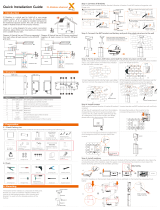
5.1 Wi-Fi module Connecon
NOTICE
Phillips Screwdriver Flat-Head Screwdriver Wire Stripper Network Wire Clamp Crimping Plier Tape Measure
1
23
PH2×150mm
2.5Nm
4
Housing
conductor
M5×12 PH2 head screw
PE Cable4
3
2
1
Step 2
1
2
Align the AC connector
Plug the AC connector
into the jack and screw tight
Step 1 Step 3
Assemble the locking cap, threaded sleeve
and swivel nut together.
Approx. 60mm
For “L”and “N”
7-9mm
Approx. 65mm for PE
Insert the crimped conductors, L, N
and PE into corresponding terminals
and tighten the screws
(torque 1.2±0.1N·m).
L
N
PE
PE
Three-core (L, N and PE) outdoor
copper cable
Conductor cross-section: 6-8 mm²
φ
•
energy release.
•
•
!
Grounding
BAT+ Power
Connector
BAT- Power
Connector
DC CablePV1-F
Conductor cross-
section4-6 mm²
Conduits
Ethernet Cables
Cat5eTP
V-resistant for
outdoor use
RJ45 Plugs PE Terminal
6-8 mm²Grid Cable
²
Three-core outdoor
copper cable
DANGER

BMS
ITEM
NC
12V
GRID_CT-
PV_CT-
DRED1/5
DO1_NO
1NO
RS485_A4
NC
GRID_CT+
PV_CT+
DRED2/6
DO1_COM
2
NC
GND
RS485_A7
RS485_A7
DRED3/7
DO1_NC
3
CAN1_H
RS485_B5
NC
NC
DRED4/8
DI_NEGATIVE
4
CAN1_L
RS485_A5
NC
NC
REFGEN/0
DI_POSITIVE
5
NC
NC
RS485_B7
RS485_B7
COMLOAD/0
GND
6
RS485_B4
NC
NC
NC
7
NC
NC
NC
NC
8
RS485
PV_CT
DRM
GRID_CT/METER
1
1 8
R 45 Pu
J
12345678
R 45 Pu
J
1.2×75mm
AUX
5.2 AUX / LAN/PV-CT Meter/DRM/GRID-CT Meter/RS485/BMS Connecon
C
PH2×150mm
1.6Nm
12
34
5.3 Wiring the Communicaon Cables between Inverter and Baery(EMS)
1
2
3
4
246
35
05 06
07 08
12
PH2×150mm
1.6Nm
1
2
3
1
2
3
Pull with hand
Without Terminal Resistor
Install the three snaps of the
corresponding holes
part on the upper cover
1
2
3)
4
5
6
7
Power ON procedure
should be pressed within 5s of previous.
) Switch on the breaker between the grid port of the inverter and the grid.
) Switch on the AC breaker between the backup port of the inverter and the loads.
) Switch on the PV switch between the external PV-inverter and the grid if there is any.
Power OFF procedure
Keep the screws on the cover (x4)
Step 1: Step 2:
Step 3: Step 4:
NEED MORE HELP?
AUX LAN DRM
RRCR PV CT
GRID CT/METER
RS485
BMS
_
_
/