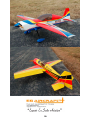
Aircraft Modelers Research Yak SP-55M User manual
- Category
- Remote controlled toys
- Type
- User manual
This manual is also suitable for

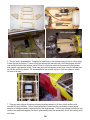
Congratulations on your purchase of this excellent almost-ready-to-fly R/C
Congratulations on your purchase of this excellent almost-ready-to-fly R/C
model! This ARF adopts the latest 3D design features and emphasizes high
performance,light weight and fun. The plane is designed by professional
engineers and built by skilled craftsmen.Many of the parts are already pre-
installed for you!
Congratulations on your purchase of this excellent almost-ready-to-fly R/C
Gasoline powered

EG AIRCRAFT
01
E-mail:[email protected]
Specifications:
Wing Span: 102 inches
Length: 95 inches (including spinner)
Wing Area: 1934 sq. in.
Flying Weight: 23 to 27 lbs
Engine: 85cc to 100cc Gas
Radio: 6 to 9 Channels
Servos : 180 - 330 oz required

02
A QUICK WORD ABOUT SAFETY AND RADIO CONTROL FLYING MODELS
With radio control aircraft, like any hobby or sport, there are certain risks. The operator of these
models is responsible for these risks. If misused or abused, you may cause serious bodily injury and/or
damage to property. With this in mind, you will want to be certain that you build your model carefully
and correctly. If you are not an experienced flier, have your work checked and ask for help in learning to
fly safely. This model aircraft is not a toy and must be operated and flown in a safe manner at all
times. Always perform a pre-flight check of the model including all control surfaces, proper function of
the radio gear, structure, radio range, and any other area relating to the safe operation of this aircraft.
By the act of using the final assembled model, the purchaser/operator accepts
all resulting liability.

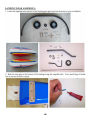
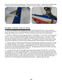
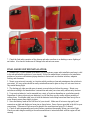
O RACO V E R Covering
03
as you can. Make sure you have a flat
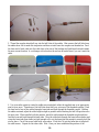
Heavy duty servo wire extensions. EG
damage and report any issues to EG as soon
Included Features:
• Carbon Fiber Wing and Stab Tubes
• Carbon Fiber Reinforced Wing and
Fuselage Spars
• Airfoiled Composite Landing Gear
• Included Servo Clips
• Complete Hardware Package
• Carbon Fiber Tail Wheel Assembly
• 4 1/2" Aluminum Spinner Included
• Long Aluminum Servo Arms
Included
• Advanced Ball Links and Pushrods
• Pre-installed Fuel Tank
•
Items Required to Complete This Model:
• 85-100 cc gas engine with stock or
aftermarket exhaust systems
• Appropriate propeller for your engine
• All required engine and exhaust mounting
hardware
• Ignition battery and switch
• One quality throttle servo and appropriate
servo arm
• Six high quality metal gear servos of 180 in-
oz or better for the ailerons and elevators
• One or two high quality rudder servos
totaling at least 330 in-oz or better
• Appropriate servo arms for the above
•
recommends two 36”, two 18”, three 12”,
two Y-harnesses, two 6”, two 6” extensions.
Your installation though may vary.
• Two heavy duty switches with charging
jacks for the Rx
• Two high quality Rx batteries of significant
capacity to power your choice of servos.
• One Receiver of your choice
Shop Supplies/Tools
• Covering Iron and heat gun
• Assortment normal hobby tools such as
screwdrivers, hobby knife, drill and drill
bits, pliers, etc.
• Thick and Thin CA adhesives
• 30 minute Epoxy
• Isopropyl alcohol
• Ruler or tape measure
• Blue thread-lock or equivalent
Note: As with all kits, it’s a good idea to read all the instructions and study the parts
before you begin construction. Handle the parts of this kit with care so you do not
damage any of the structure or covering. Inspect all the parts for any shipping
and sturdy workbench and follow all safety advice for the tools and adhesives you
plan to use.

unusually large hinge gaps. Other profiles utilize a very tight double beveled hinge line and do not
04
time and transportation. EG recommends lightly going over all the covering with a covering iron
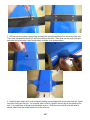
AIRCRAFT COVERING:
1. With all ARFs, varying temperatures and storage delays can cause covering material to loosen over
set at medium temperatures. Be sure to use a soft cover over your iron so you do not scratch the
covering surface. Be sure you go over all seams and edges of the covering to assure it is secure to the
airframe and other covering. Be careful not to apply too much heat or you may cause bubbles or
damage to the covering. A heat gun may also be used along with a soft cotton cloth to shrink and
adhere the covering. Again, be extremely careful when using a heat gun.
2. Carefully cut the covering away from the various openings on both sides of the fuselage. Servo
openings should be cut from corner to corner and the covering ironed down on the inside. Only cut
the throttle servo opening on the right side of the fuselage. Other holes can be cut out using either a
sharp hobby knife or the tip of a hot soldering iron. The latter technique acts to seal the covering
edges as you cut away.
3. Be sure to seal any exposed wood with a thin coating of epoxy to prevent engine oil from soaking in.
This is especially important around the engine compartment and servo openings with exposed areas.
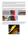
4. Some modelers prefer to seal the hinge gaps using strips of appropriate covering or clear trim tape.
We have found this to be helpful with models intended for higher speed flight or models with
normally require this step. Sealing the hinge gaps is therefore left as an option for the modeler.
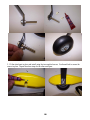
RUDDER INSTALLATION:
1. It is much easier to install the twin control horns before installing the rudder. Locate the fiberglass
rudder control horns, ball links, and associated bolts and nylon-insert lock nuts. Use some fine sandpaper
to roughen up the center areas of the two control horns so that the glue adheres better. Using a sharp
hobby knife cut the covering away from the slots in the rudder and trial fit the two control horns.
2. Mix up some 30 minute epoxy and coat the inside of the slots and the center of the control horns.
Hint: a scrap piece of 1/16” ply, toothpick, or old hobby blade can be used to coat the inside of the rudder
slots. Slide the control horns in place and make sure they are centered perfectly by using a ruler to
measure between the pivot holes and the hinge line. Wipe any excess glue off with isopropyl alcohol and
paper towels. Install the ball links, bolts and nuts into the holes to help assure alignment of both control
horns while the glue cures. Set aside until cured.

05
alcohol. EG also recommends scuffing up the plastic
3. The holes for the supplied hinge points are predrilled. Locate the hinge points and dry fit the hinges
and rudder into place and test the operation. The hinges should seat fully into the holes so that the hinge
line gap is minimal while still allowing full rudder deflection.
4. Before gluing the hinges in you must first clean the hinges of any mold release agent using isopropyl
with light sandpaper for maximum glue adhesion.
5. Mix up some 30 minute epoxy and using a toothpick or small wooden dowel coat the inside of each
hinge hole with epoxy. Also put a thin layer of epoxy on one side of the hinge points. Install this end into
the holes of the rudder and make sure each hinge is properly aligned at exactly 90 degrees to the hinge
line.
6. Now coat the other end of the hinge points with epoxy and install the rudder into the trailing edge of
the vertical stabilizer. Again, make sure the hinges remain in proper alignment. Using paper towels and
some isopropyl alcohol clean off any excess epoxy from the hinges and surrounding areas.
7. Make sure the rudder is fully seated so that the hinge gap is minimal while still allowing full deflection
of the rudder. When satisfied, use some masking tape to hold the rudder in place along the bottom and
counterbalance. After the epoxy has cured, remove the masking tape and check for proper operation. If
the hinges are dry some light oil carefully placed on each hinge will help greatly.

06

07
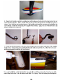
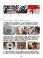
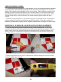
3. Bolt the gear cover plate in place using the single bolt provided and the hole in the center of the gear.
If you have purchased the Extra 300, main gear cuffs are provided. Slide these over the ends of the gear
and screw into place using 4 small wood screws as shown in the pictures below.
4. Install the main wheel axles to the composite landing gear and tighten the nylon-insert lock nut. Install
one wheel collar onto the axle. Use a second wheel collar as a guide to leave a gap on the inboard of the
axle. Use a small drop of thread-lock and tighten in place. Slide the wheel onto the axle and install a
second wheel collar also using thread-lock on the set screw.

08
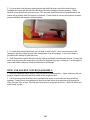
5. Fit the wheel pant in place and install using the two supplied screws. Use thread-lock to secure the
screws in place. Repeat the above steps for the other main gear.

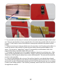
09

10
mming of servos, EG highly recommends you seek
guide and into the aluminum steering arm. Tighten the set screw firmly. Test the deflection of the rudder
to make sure there is no binding and that the steering wire does not slide out of the support guide.
RUDDER CONTROL INSTALLATION:
1. The ARF is supplied with a high quality set of pull-pull cables and ball-links. Servo openings are
provided in the aft section of the fuselage below the horizontal stabilizer for those builders using a 100 cc
engine and needing to move weight aft. The below instructions are for the pull-pull cable option.
2. Install your rudder servo(s) into the precut locations in the fuselage. You will need 3 inch arms on the
servo(s). Or you can mount the supplied rudder arm to your circular servo arm. If you use two rudder
servos it is best to connect them to two separate channels and mix them together in your radio. Set up
your radio accordingly and center the rudder servo(s). The geometry of your servo arms relative to each
other and the rudder horn is critical for proper rudder operation without binding or excess cable slack.
3. If you are using two rudder servos you will need to set up the servo coupling very accurately to assure
zero binding and drain on your batteries. Threaded couplers and ball links are provided for your use. If
you are new to multiple servo ganging and progra
the assistance of an experienced modeler in your area. Misprogramming of servos can lead to very high
drain on your batteries and possible servo failures.
4. Locate the pull-pull cable set, threaded couplers, brass swaging tubes, and ball-links. If the cable is
one long piece, cut it into two equal length pieces. Thread one end of the one cable through a brass tube
and then through one of the threaded couplers. Run the cable back through the brass tube and then loop it
back through a second time. Using a set of crimping pliers, place three crimps just tight enough not to cut
the brass tube but enough to securely hold the wire in place. Cut off the excess cable with wire cutters.
Wick thin CA into the brass tube to help hold the cable secure. Repeat for the other cable.

11
5. Thread the couplers about half way into the ball links of the rudder. Hint: remove the ball links from
the rudder horn first to make this step easier and then re-install once the couplers are threaded on. Feed
the loose end of each cable into the cable slots at the rear of the fuselage and feed them forward towards
the servo mount location. A coat hanger with a hook on the end can be useful here if you can’t reach the
cable.
6. Use your radio system to center the rudder servo and attach either the supplied arm or an appropriate
arm for your servo. Thread one of the ball links about half way onto one of the threaded couplers. Feed
the loose end of one of the cables through a brass tube and then through the threaded coupler. Holding
the rudder centered, adjust the cable length as tight as possible while checking the ball link position over
the servo arm. When satisfied with the position, pinch the cable around the threaded coupler and then
feed the loose end back through the brass tube. Loop the cable back through the brass tube as before and
crimp the brass tube three times just tight enough not to cut the brass tube but enough to securely hold the
wire in place. Cut off the excess cable with wire cutters. Wick thin CA into the brass tube to help hold
the cable secure. Repeat for the other cable. Hint: Once you have established the position of the

12
threaded coupler on the cable, you can remove the ball link from the rudder horn to give you more
working slack in the fuselage. Re-install the ball link prior to setting the other cable.
7. Check the operation of the rudder using your radio and make sure there is no binding and the cables
are adjusted properly. You may have to tighten the cables after a few flights as they may stretch slightly
from the initial installation.
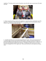
ENGINE, EXHAUST, & FUEL SYSTEM INSTALLATION:
1. Templates are provided in the kit for both DA and 3W 85 cc engines as well as the DA 100 engine.
Select the proper guide for your engine and mark and drill the mounting holes and cut out the center as
indicated. Notice that the engine center line is offset to the left to compensate for the right thrust built
into the engine box.
2. Place the cowling in place on the fuselage and measure the distance from the firewall to about 1/2” in
front of the cowling. This figure represents the back of the spinner and will help you determine if you
need to space your engine out from the firewall using washers or additional wood. Mount your engine
securely using bolts, washers, and locknuts. The use of thread-lock is also highly recommended for the
engine bolts. The pictures below show the DA85 engine installaation.
3. Mount the ignition module according to the manufacturer’s instructions. The best place to mount it is
on the side or top of the engine box. Secure the pickup lead and ignition wires with zip ties so that they
do not vibrate or touch any hot part of the engine or exhaust. The picture below shows the DA100 engine

13
installation. The author prefers to protect the ignition wires with cable wrap to prevent wear of the mesh
shielding.
4. Mount your ignition battery securely to the engine box. A typical location is on the side or top of the
engine box. The ignition switch should be mounted to the fuselage side wall just behind the cowling.
Secure all cable connections neatly and firmly.
5. Assemble the throttle servo mount using the supplied laser cut parts. This mount can be used if you
are using an engine with a rear carb such as the 85 cc engines. The typical location for this mount is
glued to the right side of the inside motor box as far aft as possible (see the photo above). Make sure you
do not have any the ignition module close to this servo. Alternatively, there is a servo cutout in the
bottom of the engine box for 100cc engine users. Mount your throttle servo and complete your linkage
setup.

14
such as the muffler or canister. EG recommends the use of small zip ties or fuel line clamps to secure
85 cc servo
location
100 cc servo location
100 cc servo location
6. The fuel tank is preassembled. Complete the installation in the fuselage using zip ties or velcro straps
to hold the tank in position. Connect a fuel line between the tank and carb, a fuel line between the tank
vent and the bottom of the fuselage, and a fill line to a fuel port which can be mounted on the fuselage
side opposite your ignition switch. Make sure your vent line does not come close to any hot exhaust part
the lines to the tank.
7. There are many options for exhaust systems including canisters of all sizes, stock mufflers, and
inverted Pitts style mufflers. Follow the manufacturer’s instructions for your exhaust system paying
attention to vibration mounts if required and air flow requirements. Trial fit your exhaust system now and
work out any additional supports, but do not permanently install the system until you fit the cowling in the
next steps.

15
elevators. Again, EG recommends you temporarily install the ball link onto the horns while the glue
COWLING INSTALLATION:
1. Fit the cowling in place and make any cutouts necessary to clear your engine and exhaust components.
Trial fit and trim as necessary being careful and accurate. Be sure to allow enough air exit area in the
bottom of the cowling to provide adequate air flow over the engine. Some modelers may prefer to build
baffling in the front of the cowling to assist air flow over the cylinders. This can be done using scrap
pieces of balsa trimmed to fit your engine installation. Be sure to fuel proof all exposed wood. When
satisfied with the final fit, attach the cowling to the fuselage using the supplies screws and rubber
washers.
2. Install the propeller and spinner. Large gasoline engines are very powerful and can cause damage to
persons or property if propellers and spinners are not installed properly. Follow the manufacturer’s
instructions and make sure your props are well balanced, properly drilled, and display no cracks or chips.
HORIZONTAL STABILIZER AND ELEVATOR CONTROLS ASSEMBLY:
1. Install the fiberglass control horns in the same way as you did the rudder horns. Do not cut the
covering on the top side of the elevators but be sure to fully seat the horns into each elevator. You may
need to trim off some of the control horns as shown in the picture below to fully seat the horns in the
cures. This will assure proper alignment of each horn.
2. Install your elevator servo into the root of the horizontal stabilizer making sure the servo wire exits
towards the leading edge of the stab.

16
3. Use your radio to set the servo center position and install the large control horn onto the servo.
Assemble the control rod and ball links and adjust the control linkage for proper geometry. When
satisfied, screw the ball link to the servo arm. The servo arm should be as close to perpendicular to the
control rod as possible while the elevator is at neutral. Double check all screws, bolts and nuts to assure
proper installation and operation without binding.
4. To install the horizontal stabilizers you first need to install two 36” servo wire extensions in the
fuselage so that they extend from the radio compartment to the aft openings. A servo wire tunnel is
provided in the fuselage to guide the wires.
5. Slide the stabilizer carbon fiber tube into the fuselage and install both stabs onto the tube. Connect the
servo wires and secure the connections with either the supplied clips, tape, or likewise. Use the supplied
screws and rubber washers to secure the stabilizers to the fuselage.
WING AND AILERON CONTROLS ASSEMBLY:
1. Install the fiberglass control horns in a similar fashion as described above. Again, make sure they are
properly aligned to each other and fully seated in their respective slots.
2. Cut the covering from the aileron servo openings from corner to corner and iron down inside the
openings. Connect servo wire extensions to your servos and secure the connections with the supplied
clips, your own clips, or tape. Feed the servo wires into the wing and out the root. Install the servos and
screw firmly in place.

17
, EG recommends you seek assistance from a local
3. Use your radio to set the centers of each servo and then assemble and adjust the length of each control
rod. The servo arm should be as close to perpendicular to the control rod as possible while the elevator is
at neutral. Double check all screws, bolts and nuts to assure proper installation and operation without
binding.
4. There are several ways to setup up multiple servos for one surface. Just like setting up the rudder, it is
critical this process is done correctly to prevent excessive battery drain and possible damage to your
servos. If you are new to “ganged servo” setups
experienced modeler or have them double check your work.
5. This manual will describe the use of two separate transmitter channels for each aileron servo. Other
options include programmable servos or matchboxes. Begin by setting the center and end points of the
inboard servo while leaving the outboard servo control rod disconnected. The center sub trim should be
as close to zero as possible.
6. Using your programmable radio, mix one of the auxiliary channels to your inboard aileron channel.
Now set the center and endpoints of this channel so that no binding occurs with the ball links. Work this
process with one end of the pushrod disconnected and trial fit the link onto the servo arm as you progress
to assure a zero-binding operation. Once satisfied, permanently attach the ball link to the servo arm with
the supplied screw and nut.

18
7. Check the final radio operation of the ailerons and make sure there is no binding or servo fighting of
each other. Also check to make sure all linkage bolts and nuts are secure.
FINAL RADIO SYSTEM INSTALLATION:
1. Whether you 72 MHz systems or the newer 2.4 GHz systems, proper radio installation and care is vital
to the safe and reliable operation of your aircraft. Follow the manufacturer’s instruction for installation
guidance of receivers and batteries paying attention to factors such as vibration isolation, adequate
cooling, and clearances.
2. Mount your reciever(s) securely in a location which provides a clean and maintenance free solution to
your setup. All servo wires should be neatly routed and secured in place so they will not come loose or
flop around during flight.
3. The fuselage ply sides provide space to mount your switches just below the canopy. Mount your
switches according to the manufacturer’s instructions and route your wires safely and securely as above.
4. Your receiver battery(s) can be mounted in a variety of locations depending on your balance needs.
Regardless of where you mount your batteries it is vital that they are very secure with no possibity of
coming loose. Use double sided vecro to hold the batteries from sliding around and then use zip ties or
vecro straps to secure them tightly in place.
5. Servo and battery leads are the life blood of your aircraft. Make sure all wires are top quality and
connectors are tight and display no loose pins or frayed wires. Servo clips are provided in the kit for your
convenience. These servo clips can even be glued to the wood structure using CA if desired.
6. Check all radio programming and control surface operations thouroughly before your initial flight.
Check your radio range according to the radio manufacturer’s instructions both with the engine off and
running.

19
EG recommends an initial CG setting of 7.0 – 8.0 inches behind the
BALANCING and PRE-FLIGHT:
1. Most state of the art aerobatic aircraft allow for a wide margin for balancing depending on what level
of precision or freestyle the pilot prefers. To perform properly without being too pitch sensitive, you must
not go too aft on the CG.
leading edge of the wing at the root. More experienced pilots may want to set the CG further aft for
more 3D capability. Varying weights of engines and radio gear will dictate how you should install each.
The batteries can easily be located pretty much anywhere in the fuselage. For those using a 100cc engine,
servo cutouts are provided in the rear of the fuselage for the rudder servos. These options should allow
you to balance the model without adding any weight.
Note: The best way to check your balance is to trim for level flight at about 1/2 to 3/4 throttle and then
roll inverted. The aircraft should maintain level flight with very little to no down elevator input. If the
aircraft climbs when inverted then you’ve probably got your CG too far aft. If the nose drops more than
slightly, then you are most likely nose heavy.
Recommended control surface deflections:
Low Rate High Rate
Elevator 15 degrees 45-50 degrees
Rudder 25 degrees 40 - 45 degrees
Ailerons 25 degrees 35-40 degrees
FINAL ASSEMBLY AND PRE-FLIGHT INSPECTIONS:
1. Before arriving at your flying field, be sure all your batteries are properly charged and all radio
systems are in proper working order.
2. Install the wings onto the fuselage being careful to align the wing tube with the wings and not force it.
The wing tube may be initially tight but will loosen some with use. Guide your servo wires into the
fuselage openings and connect to the proper aileron channels. Servo clips are recommended. Once you
have the wings fully seated in the fuselage tighten the wing bolts inside the fuselage.
3. Fill your fuel tank making sure your vent line is not plugged or capped. With the canopy off, this is a
good time to check for any fuel leaks.
4. Position the canopy in place and tighten the canopy screws. Be sure to use the supplied rubber
washers under the screw heads.
5. If you have removed your horizontal stabilizers, intall them once again and check all bolts and
connections.
6. Check all control surfaces for secure hinges by performed a slight tug on the control surfaces and
observing if there is any give in the hinges. Check all control rods, ball links, servo screws, etc. for
proper operation and installation.
7. Check your batteries and perform a proper range check once again with the engine off and running. Be
sure all surfaces are moving in the correct direction and the proper amount for your flying setup.
8. You are now ready for your maiden flight! Good luck and enjoy your new aircraft! If you have any
comments or questions about this manual or the aircraft please email “ ”.
Page is loading ...
-
 1
1
-
 2
2
-
 3
3
-
 4
4
-
 5
5
-
 6
6
-
 7
7
-
 8
8
-
 9
9
-
 10
10
-
 11
11
-
 12
12
-
 13
13
-
 14
14
-
 15
15
-
 16
16
-
 17
17
-
 18
18
-
 19
19
-
 20
20
-
 21
21


Aircraft Modelers Research Yak SP-55M User manual
- Category
- Remote controlled toys
- Type
- User manual
- This manual is also suitable for
Ask a question and I''ll find the answer in the document
Finding information in a document is now easier with AI
Other documents
-
AeroWorks YAK 54 ARF-QB Assembly Manual
-
-
-
-
 Game Of Bricks UCS 7181 Light Kit for Star Wars TIE Interceptor User manual
-
-
-
-
-
