Page is loading ...

Troubleshooting
Guide
1336 IMPACTt
Adjustable Frequency
AC Drive
(Series A)
A020 – A030
B040 – B050
BX040, BX060
C025 – C060
Allen-Bradley
AB Spares

Because of the variety of uses for the products described in this publication,
those responsible for the application and use of this control equipment must
satisfy themselves that all necessary steps have been taken to assure that
each application and use meets all performance and safety requirements,
including any applicable laws, regulations, codes and standards.
The illustrations, charts, sample programs and layout examples
shown in this guide are intended solely for purposes of example.
Since there are many variables and requirements associated with any
particular installation, Rockwell Automation does not assume
responsibility or liability (to include intellectual property liability)
for actual use based upon the examples shown in this publication.
Rockwell Automation publication SGI-1.1, Safety Guidelines for the
Application, Installation, and Maintenance of Solid-State Control
(available from your local Rockwell Automation office), describes
some important differences between solid-state equipment and
electromechanical devices that should be taken into consideration
when applying products such as those described in this publication.
Reproduction of the contents of this copyrighted publication, in
whole or in part, without written permission of Rockwell
International Corporation, is prohibited.
Throughout this manual we use notes to make you aware of safety
considerations:
!
ATTENTION: Identifies information about practices
or circumstances that can lead to personal injury or
death, property damage or economic loss.
Attention statements help you to:
• identify a hazard
• avoid the hazard
• recognize the consequences
Important: Identifies information that is critical for successful
application and understanding of the product.
Important User
Information

CUT ALONG DOTTED LINE ✁
We Want Our Manuals to be the Best!
You can help! Our manuals must meet the needs of you, the user. This is your opportunity to make sure they
do just that. By filling out this form you can help us provide the most useful, thorough, and accurate manuals
available. Please take a few minutes to tell us what you think. Then mail or FAX this form.
FAX: to your local Allen-Bradley Sales Office or 414/512-8579
PUBLICATION NAME
PUBLICATION NUMBER, DATE AND PART NUMBER (IF PRESENT)
✓ CHECK THE FUNCTION THAT MOST CLEARLY DESCRIBES YOUR JOB.
- SUGGEST / RESPONSIBLE FOR THE PURCHASE OF EQUIPMENT - MAINTAIN / OPERATE PROGRAMMABLE MACHINERY
- DESIGN / IMPLEMENT ELECTRICAL SYSTEMS - TRAIN/EDUCATE MACHINE USERS
- SUPERVISE FLOOR OPERATIONS
✓ WHAT LEVEL OF EXPERIENCE DO YOU HAVE WITH EACH OF THE FOLLOWING PRODUCTS?
NONE LITTLE MODERATE EXTENSIVE
PROGRAMMABLE CONTROL ----
AC / DC DRIVES ----
PERSONAL COMPUTERS ----
NC / CNC CONTROLS ----
DATA COMMUNICATIONS / LAN ----
✓ RATE THE OVERALL QUALITY OF THIS MANUAL BY CIRCLING YOUR RESPONSE BELOW. (1) = POOR (5) = EXCELLENT
HELPFULNESS OF INDEX / TABLE OF CONTENTS 1 2 3 4 5
CLARITY 1 2 3 4 5
EASE OF USE 1 2 3 4 5
ACCURACY AND COMPLETENESS 1 2 3 4 5
QUALITY COMPARED TO OTHER COMPANIES’ MANUALS 1 2 3 4 5
QUALITY COMPARED TO OTHER ALLEN-BRADLEY MANUALS 1 2 3 4 5
✓ WHAT DID YOU LIKE MOST ABOUT THIS MANUAL?
✓ WHAT DID YOU LIKE LEAST ABOUT THIS MANUAL?
✓ PLEASE LIST ANY ERRORS YOU FOUND IN THIS MANUAL (REFERENCE PAGE, TABLE, OR FIGURE NUMBERS).
✓ DO YOU HAVE ANY ADDITIONAL COMMENTS?
✓ COMPLETE THE FOLLOWING.
NAME COMPANY
TITLE DEPARTMENT
STREET CITY STATE ZIP
TELEPHONE DATE
AB Spares

FOLD HERE
FOLD HERE
NO POSTAGE
NECESSARY
IF MAILED
IN THE
UNITED STATES
BUSINESS REPLY MAIL
PERMIT NO. 413 MEQUON, WI
POSTAGE WILL BE PAID BY ADDRESSEE
ALLEN-BRADLEY
Attn: Marketing Communications
P.O. Box 760
Mequon, WI 53092-9907
FIRST CLASS

Summary of Changes
Publication 1336 IMPACT-6.2 – March 1998
Summary of Changes
The information below summarizes the changes to the
company-wide templates since the last release.
No changes have been made to this manual.
Updated Information
AB Spares

Publication 1336 IMPACT-6.2 – March 1998
Manual Objective P–1. . . . . . . . . . . . . . . . . . . . . . . . . . . . . . . . . . . . .
Who Should Use This Manual P–1. . . . . . . . . . . . . . . . . . . . . . . . . . . .
Safety Precautions P–1. . . . . . . . . . . . . . . . . . . . . . . . . . . . . . . . . . . .
Electrostatic Discharge Precautions P–2. . . . . . . . . . . . . . . . . . . . . . .
1336 IMPACT Product Identification P–3. . . . . . . . . . . . . . . . . . . . . . .
Drive Nameplate Location P–3. . . . . . . . . . . . . . . . . . . . . . . . . . . .
Drive and Option Identification P–4. . . . . . . . . . . . . . . . . . . . . . . . . . .
1336 IMPACT Drive Catalog Numbers P–4. . . . . . . . . . . . . . . . . . . .
Drive Rating Qualifications P–9. . . . . . . . . . . . . . . . . . . . . . . . . . . .
Enclosure Type P–9. . . . . . . . . . . . . . . . . . . . . . . . . . . . . . . . . . . .
Conventions P–10. . . . . . . . . . . . . . . . . . . . . . . . . . . . . . . . . . . . . . . .
Auxiliary Interlock P–10. . . . . . . . . . . . . . . . . . . . . . . . . . . . . . . . . .
Bit P–10. . . . . . . . . . . . . . . . . . . . . . . . . . . . . . . . . . . . . . . . . . . . .
Check P–10. . . . . . . . . . . . . . . . . . . . . . . . . . . . . . . . . . . . . . . . . . .
Connector P–10. . . . . . . . . . . . . . . . . . . . . . . . . . . . . . . . . . . . . . . .
Default P–10. . . . . . . . . . . . . . . . . . . . . . . . . . . . . . . . . . . . . . . . . .
Enable Input P–11. . . . . . . . . . . . . . . . . . . . . . . . . . . . . . . . . . . . . .
False P–11. . . . . . . . . . . . . . . . . . . . . . . . . . . . . . . . . . . . . . . . . . .
Jumper P–11. . . . . . . . . . . . . . . . . . . . . . . . . . . . . . . . . . . . . . . . . .
L Option Board P–11. . . . . . . . . . . . . . . . . . . . . . . . . . . . . . . . . . . .
Not External Fault Input P–11. . . . . . . . . . . . . . . . . . . . . . . . . . . . . .
Parameter P–11. . . . . . . . . . . . . . . . . . . . . . . . . . . . . . . . . . . . . . . .
Press P–12. . . . . . . . . . . . . . . . . . . . . . . . . . . . . . . . . . . . . . . . . . .
True P–12. . . . . . . . . . . . . . . . . . . . . . . . . . . . . . . . . . . . . . . . . . . .
Related Publications P–12. . . . . . . . . . . . . . . . . . . . . . . . . . . . . . . . . .
Chapter 1
Chapter Objectives 1–1. . . . . . . . . . . . . . . . . . . . . . . . . . . . . . . . . . .
Chapter Overview 1–1. . . . . . . . . . . . . . . . . . . . . . . . . . . . . . . . . . . .
L Option Board 1–2. . . . . . . . . . . . . . . . . . . . . . . . . . . . . . . . . . . . . .
L Option Board Jumpers 1–3. . . . . . . . . . . . . . . . . . . . . . . . . . . . . .
Available Inputs 1–4. . . . . . . . . . . . . . . . . . . . . . . . . . . . . . . . . . . .
Local Programming 1–5. . . . . . . . . . . . . . . . . . . . . . . . . . . . . . . . . . .
Human Interface Module (HIM) 1–9. . . . . . . . . . . . . . . . . . . . . . . . . . .
Description 1–9. . . . . . . . . . . . . . . . . . . . . . . . . . . . . . . . . . . . . . .
Removing the HIM 1–10. . . . . . . . . . . . . . . . . . . . . . . . . . . . . . . . . .
HIM Operation 1–12. . . . . . . . . . . . . . . . . . . . . . . . . . . . . . . . . . . . .
Graphic Programming Terminal 1–12. . . . . . . . . . . . . . . . . . . . . . . . . . .
GPT Description 1–12. . . . . . . . . . . . . . . . . . . . . . . . . . . . . . . . . . .
DriveTools 1–13. . . . . . . . . . . . . . . . . . . . . . . . . . . . . . . . . . . . . . . . . .
Control Firmware Function 1–13. . . . . . . . . . . . . . . . . . . . . . . . . . . . . .
Table of Contents
Preface
Control Logic Wiring and
Adapters

Table of Contentsii
Publication 1336 IMPACT-6.2 – March 1998
Chapter 2
Chapter Objectives 2–1. . . . . . . . . . . . . . . . . . . . . . . . . . . . . . . . . . .
Fault/Warning Handling 2–1. . . . . . . . . . . . . . . . . . . . . . . . . . . . . . . .
Viewing the Fault and Warning Queues on the HIM 2–3. . . . . . . . . . . .
What Are the Fault Descriptions 2–4. . . . . . . . . . . . . . . . . . . . . . . . . .
Diagnostic Procedures by Symptom 2–14. . . . . . . . . . . . . . . . . . . . . . .
Start Up Troubleshooting Procedures 2–18. . . . . . . . . . . . . . . . . . . . . .
Miscellaneous Troubleshooting Procedures 2–18. . . . . . . . . . . . . . . . . .
Encoderless Troubleshooting Procedures 2–20. . . . . . . . . . . . . . . . . . .
Chapter 3
Chapter Objectives 3–1. . . . . . . . . . . . . . . . . . . . . . . . . . . . . . . . . . .
Disassembly and Access Overview 3–1. . . . . . . . . . . . . . . . . . . . . . . .
Electrostatic Discharge Precautions 3–1. . . . . . . . . . . . . . . . . . . . . . .
Tools 3–2. . . . . . . . . . . . . . . . . . . . . . . . . . . . . . . . . . . . . . . . . . .
Fastener Torque Specifications 3–3. . . . . . . . . . . . . . . . . . . . . . . . . . .
Torque Sequence 3–3. . . . . . . . . . . . . . . . . . . . . . . . . . . . . . . . . .
Two-Point Mounting 3–3. . . . . . . . . . . . . . . . . . . . . . . . . . . . . . .
Four-Point Mounting 3–3. . . . . . . . . . . . . . . . . . . . . . . . . . . . . . .
Torque Specifications 3–4. . . . . . . . . . . . . . . . . . . . . . . . . . . . . . . .
Disassembly and Access Procedures 3–5. . . . . . . . . . . . . . . . . . . . . .
Opening the Drive Enclosure 3–5. . . . . . . . . . . . . . . . . . . . . . . . . .
Removal 3–6. . . . . . . . . . . . . . . . . . . . . . . . . . . . . . . . . . . . . . .
Installation 3–6. . . . . . . . . . . . . . . . . . . . . . . . . . . . . . . . . . . . . .
Removing L Option Board 3–7. . . . . . . . . . . . . . . . . . . . . . . . . . . .
Removal 3–8. . . . . . . . . . . . . . . . . . . . . . . . . . . . . . . . . . . . . . .
Installation 3–8. . . . . . . . . . . . . . . . . . . . . . . . . . . . . . . . . . . . . .
Removing the Main Control Board Mounting Plate 3–9. . . . . . . . . . .
Removal 3–9. . . . . . . . . . . . . . . . . . . . . . . . . . . . . . . . . . . . . . .
Installation 3–10. . . . . . . . . . . . . . . . . . . . . . . . . . . . . . . . . . . . . .
Removing the Main Control Board 3–11. . . . . . . . . . . . . . . . . . . . . . .
Removal 3–11. . . . . . . . . . . . . . . . . . . . . . . . . . . . . . . . . . . . . . .
Installation 3–12. . . . . . . . . . . . . . . . . . . . . . . . . . . . . . . . . . . . . .
Removing the Precharge Board 3–13. . . . . . . . . . . . . . . . . . . . . . . .
Removal 3–13. . . . . . . . . . . . . . . . . . . . . . . . . . . . . . . . . . . . . . .
Installation 3–14. . . . . . . . . . . . . . . . . . . . . . . . . . . . . . . . . . . . . .
Removing the Gate Driver Board 3–15. . . . . . . . . . . . . . . . . . . . . . . .
Removal 3–15. . . . . . . . . . . . . . . . . . . . . . . . . . . . . . . . . . . . . . .
Installation 3–16. . . . . . . . . . . . . . . . . . . . . . . . . . . . . . . . . . . . . .
Removing the Snubber Board 3–17. . . . . . . . . . . . . . . . . . . . . . . . . .
Removal 3–17. . . . . . . . . . . . . . . . . . . . . . . . . . . . . . . . . . . . . . .
Installation 3–19. . . . . . . . . . . . . . . . . . . . . . . . . . . . . . . . . . . . . .
Accessing Chassis Power Components 3–19. . . . . . . . . . . . . . . . . . .
Troubshooting and Error
Codes
Disassembly and Access
Procedures
AB Spares

Table of Contents iii
Publication 1336 IMPACT-6.2 – March 1998
Chapter 4
Chapter Objectives 4–1. . . . . . . . . . . . . . . . . . . . . . . . . . . . . . . . . . .
Component Test Overview 4–1. . . . . . . . . . . . . . . . . . . . . . . . . . . . . .
Electrostatic Discharge Precautions 4–2. . . . . . . . . . . . . . . . . . . . . . .
Tools 4–2. . . . . . . . . . . . . . . . . . . . . . . . . . . . . . . . . . . . . . . . . . .
Test 1 – Testing Input Rectifier SCR1 4–3. . . . . . . . . . . . . . . . . . . . . . .
Test 2 – Testing the Bus Capacitor Bank 4–5. . . . . . . . . . . . . . . . . . . .
Test 3 – Testing Power Modules PM1 – PM3 4–8. . . . . . . . . . . . . . . . .
Test 4 – Testing Bus Fuse F1 4–10. . . . . . . . . . . . . . . . . . . . . . . . . . . .
Test 5 – Testing the Gate Driver Board 4–12. . . . . . . . . . . . . . . . . . . . . .
Test 6 – Testing the Precharge Board 4–14. . . . . . . . . . . . . . . . . . . . . .
Test 7 – Testing the Thermistor 4–16. . . . . . . . . . . . . . . . . . . . . . . . . . .
Chapter 5
Chapter Objective 5–1. . . . . . . . . . . . . . . . . . . . . . . . . . . . . . . . . . . .
Part Replacement Overview 5–1. . . . . . . . . . . . . . . . . . . . . . . . . . . . .
Safety Precautions 5–1. . . . . . . . . . . . . . . . . . . . . . . . . . . . . . . . . . . .
Electrostatic Discharge Precautions 5–1. . . . . . . . . . . . . . . . . . . . . . .
Tools 5–2. . . . . . . . . . . . . . . . . . . . . . . . . . . . . . . . . . . . . . . . . . .
Major Component Replacement 5–2. . . . . . . . . . . . . . . . . . . . . . . . . .
Detailed Product Identification 5–2. . . . . . . . . . . . . . . . . . . . . . . . . . . .
Ground Sense CT 5–4. . . . . . . . . . . . . . . . . . . . . . . . . . . . . . . . . .
Removal 5–4. . . . . . . . . . . . . . . . . . . . . . . . . . . . . . . . . . . . . . .
Installation 5–6. . . . . . . . . . . . . . . . . . . . . . . . . . . . . . . . . . . . . .
Bus Fuse F1 5–7. . . . . . . . . . . . . . . . . . . . . . . . . . . . . . . . . . . . . .
Removal 5–8. . . . . . . . . . . . . . . . . . . . . . . . . . . . . . . . . . . . . . .
Installation 5–8. . . . . . . . . . . . . . . . . . . . . . . . . . . . . . . . . . . . . .
Thermistor 5–9. . . . . . . . . . . . . . . . . . . . . . . . . . . . . . . . . . . . . . .
Removal 5–9. . . . . . . . . . . . . . . . . . . . . . . . . . . . . . . . . . . . . . .
Installation 5–10. . . . . . . . . . . . . . . . . . . . . . . . . . . . . . . . . . . . . .
Power Modules PM1 – PM3 5–11. . . . . . . . . . . . . . . . . . . . . . . . . . .
Removal 5–11. . . . . . . . . . . . . . . . . . . . . . . . . . . . . . . . . . . . . . .
Installation 5–12. . . . . . . . . . . . . . . . . . . . . . . . . . . . . . . . . . . . . .
Input Rectifier SCR1 5–13. . . . . . . . . . . . . . . . . . . . . . . . . . . . . . . .
Removal 5–13. . . . . . . . . . . . . . . . . . . . . . . . . . . . . . . . . . . . . . .
Installation 5–14. . . . . . . . . . . . . . . . . . . . . . . . . . . . . . . . . . . . . .
Fan 5–15. . . . . . . . . . . . . . . . . . . . . . . . . . . . . . . . . . . . . . . . . . . .
Removal 5–16. . . . . . . . . . . . . . . . . . . . . . . . . . . . . . . . . . . . . . .
Installation 5–17. . . . . . . . . . . . . . . . . . . . . . . . . . . . . . . . . . . . . .
DC Bus Inductor L1 5–18. . . . . . . . . . . . . . . . . . . . . . . . . . . . . . . . .
Removal 5–19. . . . . . . . . . . . . . . . . . . . . . . . . . . . . . . . . . . . . . .
Installation 5–20. . . . . . . . . . . . . . . . . . . . . . . . . . . . . . . . . . . . . .
Component Test Procedures
Part Replacement
Procedures

Table of Contentsiv
Publication 1336 IMPACT-6.2 – March 1998
Bus Capacitor Bank 5–21. . . . . . . . . . . . . . . . . . . . . . . . . . . . . . . . .
Removal 5–21. . . . . . . . . . . . . . . . . . . . . . . . . . . . . . . . . . . . . . .
Installation 5–23. . . . . . . . . . . . . . . . . . . . . . . . . . . . . . . . . . . . . .
Fan 5–15. . . . . . . . . . . . . . . . . . . . . . . . . . . . . . . . . . . . . . . . . . . .
Chapter 6
Chapter Objectives 6–1. . . . . . . . . . . . . . . . . . . . . . . . . . . . . . . . . . .
Ordering Replacement Parts 6–1. . . . . . . . . . . . . . . . . . . . . . . . . . . . .
Replacement Parts Listing 6–2. . . . . . . . . . . . . . . . . . . . . . . . . . . . . .
Chapter 7
Replacement Parts List
Schematics — 20 – 60 HP
1336 IMPACT Drives
Index
AB Spares

Preface
P–1
Publication 1336 IMPACT-6.2 – March 1998
Preface
The information in this manual is designed to help troubleshoot or
repair an Allen-Bradley Bulletin 1336 IMPACT Adjustable
Frequency AC Drive with ratings A020 – A030, B040, B050,
BX040, BX060, and C025 – C060.
This manual is intended for qualified service personnel responsible
for troubleshooting and repairing the 1336 IMPACT Adjustable
Frequency AC Drive. You should:
• Read this entire manual before performing maintenance or repairs
to drives.
• Have previous experience with, and basic understanding of,
electrical terminology, procedures, required troubleshooting
equipment, equipment protection procedures and methods, and
safety precautions.
This manual describes equipment, troubleshooting, and disassembly
procedures. You begin with general illustrations and end with greater
detail concerning replacement parts and part locations on the drives.
Later chapters may refer you back to earlier chapters for information
on basic equipment and steps necessary to perform detailed
diagnostics and part replacement.
!
ATTENTION: Some printed circuit boards and drive
components may contain hazardous voltage levels.
Remove and lock out power before you disconnect or
reconnect wires and before you remove or replace
fuses and circuit boards. Verify bus voltage by
measuring the voltage between +DC and –DC on
terminal block TB1. Do not attempt to service the drive
until the bus voltage has discharged to zero volts.
Manual Objective
Who Should Use This
Manual
Safety Precautions

PrefaceP–2
Publication 1336 IMPACT-6.2 – March 1998
!
ATTENTION: Potentially fatal voltages may result
from improper usage of oscilloscope and other test
equipment. The oscilloscope chassis may be at a
potentially fatal voltage if not properly grounded. If an
oscilloscope is used to measure high voltage
waveforms, use only a dual channel oscilloscope in the
differential mode with X 100 probes. It is
recommended that the oscilloscope be used in the A
minus B Quasi-differential mode with the oscilloscope
chassis correctly grounded to an earth ground.
!
ATTENTION: Only personnel familiar with the
1336 IMPACT Adjustable Frequency AC Drive and
associated machinery should plan or implement the
installation, start-up and subsequent maintenance of the
system. Failure to comply may result in personal injury
and/or equipment damage.
!
ATTENTION: This assembly contains parts and
sub-assemblies that are sensitive to electrostatic
discharge. Static control precautions are required when
servicing this assembly. Component damage may result
if you ignore electrostatic discharge control procedures.
If you are not familiar with static control procedures,
reference Rockwell Automation Publication
8000-4.5.2, Guarding Against Electrostatic Damage, or
any other applicable ESD protection handbook.
Electrostatic discharge generated by static electricity can damage the
complementary metallic oxide semiconductor devices on various
drive boards. It is recommended that you perform these procedures
to guard against this type of damage when circuit boards are
removed or installed:
• Wear a wrist-type grounding strap that is grounded to the drive
chassis.
• Attach the wrist strap before removing the new circuit board from
the conductive packet.
• Remove boards from the drive and immediately insert them into
their conductive packets.
Electrostatic Discharge
Precautions
AB Spares

Preface P–3
Publication 1336 IMPACT-6.2 – March 1998
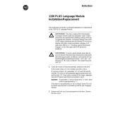
Drive Nameplate Location
The drive nameplate is located on the face of the Main Control
Board Mounting Plate. The drive nameplate contains the drive’s
catalog number and other important drive information. Reference the
catalog number when ordering replacement parts.
Figure P.1
Drive Nameplate Location
AB0334B
Nameplate located on tab
of Main Control Board
Mounting Plate
1336 IMPACT Product
Identification

PrefaceP–4
Publication 1336 IMPACT-6.2 – March 1998
The following is an explanation of the catalog numbering system for
1336 IMPACT Adjustable Frequency AC Drives and options. The
catalog number is coded to identify the drive power rating and can be
found on the drive shipping carton and nameplate.
1336 IMPACT Drive Catalog Numbers
Table P.A
200 – 240V AC Input
1336E
– A020-AN – EN – L6 – HA1 – GM1
Bulletin No. Rating-Enclosure
(Must Be Specified)
Language Module
(Must Be Specified)
L Option
(Optional)
Human
Interface
(Optional)
Communication Card
(Optional)
Enclosures
Drive Rating
Open IP00
No Enclosure
NEMA Type 1 IP20
General Purpose
NEMA Type 4
IP65
Resist Water, Dust
NEMA Type 12
IP54
Industrial Use
Frame
Designation
Output
Amps
Nominal
HP
Code
Code
Code Code
C
AA
AAAA
AA
AA
C
64.5 20
A
020–
A
N
AA
A
020–
AA
, –
A
E
AAAA
A
020–
A
F
AA
A
020–
A
J
AA
78.2
80.0
25
30
A025–AN
A030–AN
A025–AA, –AE
A030–AA, –AE
A025–AF
A030–AF
A025–AJ
A030–AJ
Refer to the Language Module and Options tables following these Catalog Number tables.
200 – 240V AC drive rating is based on nominal voltage of 240V and carrier frequency of 4kHz (60HP/45kW and below) or 2kHz (75HP/55kW and above)
at altitudes of 1,000 meters or less. 380 – 480VAC drive rating is based on nominal voltage of 480V and carrier frequency of 4kHz (60HP/45kW and below) or 2kHz
(75HP/55kW and above) at altitudes of 1,000 meters or less. 500 – 600V AC drive rating is based on nominal voltage of 600v and carrier frequency of 4kHz
(60HP/45kW and below) or 2kHz (75HP/55kW and above) at altitudes of 1,000 meters or less. Refer to Drive Rating Qualifications on page P–9.
Refer to Table P.I for explanation of “E” rating.
Drive and Option
Identification
AB Spares

Preface P–5
Publication 1336 IMPACT-6.2 – March 1998
Table P.B
380 – 480V AC Input
1336E
– B040-AN – EN – L6 – HA1 – GM1
Bulletin No. Rating-Enclosure
(Must Be Specified)
Language Module
(Must Be Specified)
L Option
(Optional)
Human Interface
(Optional)
Communication Card
(Optional)
Enclosures
Drive Rating
Open
IP00
No Enclosure
NEMA Type 1 IP20
General Purpose
NEMA Type 4 IP56
Resist Water, Dust
NEMA Type 12 IP54
Industrial Use
Frame
Designation
Output
Amps
Nominal
HP
Code
Code
Code Code
C 58.7
64.5
78.2
78.2
40
40
50
60
BX040–AN
B040–AN
B050–AN
BX060–AN
BX040–AA, –AE
B040–AA, –AE
B050–AA, –AE
BX060–AA, –AE
BX040–AF
B040–AF
B050–AF
BX060–AF
BX040–AJ
B040–AJ
B050–AJ
BX060–AJ
Refer to the Language Module and Options tables following these Catalog Number tables.
200 – 240V AC drive rating is based on nominal voltage of 240V and carrier frequency of 4kHz (60HP/45kW and below) or 2kHz (75HP/55kW and above)
at altitudes of 1,000 meters or less. 380 – 480VAC drive rating is based on nominal voltage of 480V and carrier frequency of 4kHz (60HP/45kW and below) or 2kHz
(75HP/55kW and above) at altitudes of 1,000 meters or less. 500 – 600V AC drive rating is based on nominal voltage of 600v and carrier frequency of 4kHz
(60HP/45kW and below) or 2kHz (75HP/55kW and above) at altitudes of 1,000 meters or less. Refer to Drive Rating Qualifications on page P–9.
Refer to Table P.I for explanation of “E” rating.

PrefaceP–6
Publication 1336 IMPACT-6.2 – March 1998
Table P.C
500 – 600V AC Input
1336E
– C025-AN – EN – L6 – HA1 – GM1
Bulletin No. Rating Enclosure
(Must Be Specified)
Language Module
(Must Be Specified)
L Option
(Optional)
Human Interface
(Optional)
Communication
Card
(Optional)
Enclosures
Drive Rating
Open
IP00
No Enclosure
NEMA Type 1
IP20
General Purpose
NEMA Type 4
IP56
Resist Water, Dust
NEMA Type 12
IP54
Industrial Use
Frame
Designation
Output
Amps
Nominal
HP
Code Code Code Code
C 30.0 25 C025–AN
CA
C025–AA
CAA
C025–AF
CA
C025–AJ
CA
34.6
45.1
30
40
C
030–
A
N
C040–AN
CA
C
030–
AA
C040–AA
CAA
C
030–
A
F
C040–AF
CA
C
030–
A
J
C040–AJ
CA
57.2
61.6
50
60
C
050–
A
N
C060–AN
C
050–
AA
C060–AA
C
050–
A
F
C060–AF
C
050–
A
J
C060–AJ
Refer to the Language Module and Options tables following these Catalog Number tables.
200 – 240V AC drive rating is based on nominal voltage of 240V and carrier frequency of 4kHz (60HP/45kW and below) or 2kHz (75HP/55kW and above)
at altitudes of 1,000 meters or less. 380 – 480VAC drive rating is based on nominal voltage of 480V and carrier frequency of 4kHz (60HP/45kW and below) or 2kHz
(75HP/55kW and above) at altitudes of 1,000 meters or less. 500 – 600V AC drive rating is based on nominal voltage of 600v and carrier frequency of 4kHz
(60HP/45kW and below) or 2kHz (75HP/55kW and above) at altitudes of 1,000 meters or less. Refer to Drive Rating Qualifications on page P–9.
AB Spares

Preface P–7
Publication 1336 IMPACT-6.2 – March 1998
Table P.D
Language Modules
Description
Option Code
English/English
English/French
English/German
English/Italian
English/Japanese
English/Spanish
EN
FR
DE
IT
JP
ES
Not available at time of printing.
Table P.E
Options
Code
Description
Code
Description
Human Interface Modules, NEMA Type 1 (IP20) Communication Options
HAB
HAP
HA1
HA2
Blank – No Functionality
Programmer Only
Programmer/Controller with Analog Pot
Programmer/Controller with Digital Pot
GM1
GM2
GM5
Single Point Remote I/O
RS-232/422/485, DF1, & DH485 Protocol
DeviceNet™
Human Interface Modules, NEMA Type 4/12 (IP65/54) L Option Boards
HJP
HJ2
Programmer Only
Programmer/Controller with Digital Pot
L4
L7E
L5
L8E
L6
L9E
Contact Closure
Contact Closure & Encoder Feedback
+24V AC/DC
+24V AC/DC & Encoder Feedback
115V AC
115V AC & Encoder Feedback
For a more functionally complete description of each option, refer to Publication 1336 IMPACT-1.0.

PrefaceP–8
Publication 1336 IMPACT-6.2 – March 1998
Table P.F
200 – 240V Drives
Catalog
Number
Maximum
Amp
Rating
Derate
Curve
Heat
Dissipation
Drive
Watts
Heat Sink
Watts
Total Watts
A020
A025
A030
65
78
80
None
210
215
220
933
1110
1110
1143
1325
1330
Table P.G
380 – 480V Drives
Catalog
Number
Maximum
Amp
Rating
Derate
Curve
Heat
Dissipation
Drive
Watts
Heat Sink
Watts
Total Watts
B040
B050
BX040
BX060
65
78
59
78
175
193
175
193
933
1110
933
1110
1108
1303
1108
1303
Table P.H
500 – 600V Drives
Catalog
Number
Maximum
Amp
Rating
Derate
Curve
Heat
Dissipation
Drive
Watts
Heat Sink
Watts
Total Watts
C025
C030
C040
C050
C060
30
35
45
57
62
None
None
None
None
None
141
141
175
193
193
492
526
678
899
981
633
667
853
1092
1174
Amp Rating is at 4kHz. If carrier frequencies above 4kHz are selected, drive Amp Rating must be
derated.
Drive Rating is based on nominal voltage (240, 480, or 600V). If input voltage exceeds Drive
Rating, Drive Output must be derated.
Drive Ambient Temperature Rating is 40_C. If ambient exceeds 40_C, the drive must be derated.
Drive Rating is based on altitudes of 1,000m (3,000 ft) or less. If installed at higher altitude, drive
must be derated.
Refer to the 1336 IMPACT User Manual.
AB Spares

Preface P–9
Publication 1336 IMPACT-6.2 – March 1998
Drive Rating Qualifications
Several factors can affect drive rating. If more than one factor exists,
derating percentages must be multiplied. For example, if a 14-amp
drive is installed at a 2km (6,600 ft.) altitude and has a 2%
high-input line voltage, the actual amp rating is: 14 x 94% altitude
derating x 96% high-input line derating = 12.6 amps
Enclosure Type
The first character, A, indicates the Enclosure Code.
The second character indicates the type of enclosure shipped from
the factory:
Table P.I
Enclosure Type Code Description
Enclosure
Type Code
Description
N
A
E
F
J
Open style (IP00)
NEMA Type 1 (IP20)
NEMA Type 1 (IP20) “CE” Metal Cover
NEMA Type 4 (IP65)
NEMA Type 12 (IP54)

PrefaceP–10
Publication 1336 IMPACT-6.2 – March 1998
To help differentiate parameter names and display text from other
text in this manual, the following conventions will be used:
• Parameter Names will appear in italics.
• Display Text will appear in “quotes”.
The following is a list of conventions used throughout this manual,
and definitions of the conventions. For a list of terminology and
definitions, refer to the Glossary in the back of this manual.
Auxiliary Interlock
The Auxiliary Interlock is a user supplied circuit consisting of reset,
overload, or other interlocking circuitry. The Interlock is wired to the
drive Not External Fault Input.
Bit
A bit is a single character or status point used in programmable
logic. Eight bits form a BYTE, 16 bits form a word. Drive
parameters are actually eight bits or 16 bit words.
Check
To check means to examine either the physical condition of
something or the setting of some control, such as a Parameter.
Checking a drive board or component may also require
measurements and tests.
Connector
A connector connects one drive board to another. Connectors come
in two designs, male and female. Male connectors are stationary and
contain pins, which are sometimes joined by jumpers. Female
connectors are at the ends of wires or ribbon cables and plug into
male connectors.
Default
When a drive function defaults, it automatically changes to a
pre-programmed setting.
Conventions
AB Spares

Preface P–11
Publication 1336 IMPACT-6.2 – March 1998
Enable Input
The Enable Input is a terminal connection on the L Option Board.
This connection provides an external input to enable or disable the
Drive Output section. It must be true to permit the drive to operate.
False
False refers to a logical false state. For instance, an L Option signal
on TB3 is false when the input contact is open or the appropriate
voltage is not applied to the L Option Board.
Jumper
A jumper completes a circuit between two pins within a male
connector on a drive board. In the absence of certain optional
equipment using female connectors, jumpers are applied to certain
pins within a male connector to complete specific and necessary
circuits.
L Option Board
An L Option Board plugs into connectors J7 and J9, located on the
lower portion of the Main Control Board. This board is identified as
L4, L5, L6, L7E, L8E, and L9E and provides optional control wiring
configurations for a drive.
Not External Fault Input
The Not External Fault Input is a terminal connection on the L
Option Board. This connection provides an external input for use as
an Auxiliary Interlock. Unless this interlock is closed, the drive will
be faulted with an External Fault.
Parameter
Parameters are programmable drive functions that define various
operating functions or status displays of a drive. Refer to Bulletin
1336 IMPACT Adjustable Frequency AC Drive User Manual for
parameter details.
/