Page is loading ...

FLEX I/O is a trademark of AllenBradley Co. Inc.
SCANport is a trademark of Allen-Bradley Co. Inc.
FLEX I/Ot SCANportt
Terminal Base
(Cat. No. 1203FB1)
Installation
Instructions
Channel 1 Channel 2
SCANport
1
2
3
4
6
8
0
1
2
3
4
5
6
7
8
9
10

FLEX I/O SCANportt Base Installation Instructions
1–2
1203-5.7ML- April 1996
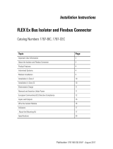
Component
Identification
1 Module locking latch
2
Keyswitch - Set to the position required for the installed module
3
Male flexbus connector (beneath the cover plug)
4 Cover plug for male flexbus connector
5
Key slot for attaching to 1203 module
6
Channel 2 SCANport connector
7 Locking tab for DIN rail
8
Channel 1 SCANport connector
9
Mounting holes for panel mounting
10 Female flexbus connector

FLEX I/O SCANportt Base Installation Instructions
1–3
1203-5.7ML- April 1996
Mounting on a DIN Rail
B
C
A
D
DIN
Rail
Side View
Locking
Lever
(D)
1
2
3
4
0
9
8
6
!
ATTENTION: Do not remove or replace a terminal base unit when
power is applied. Interruption of the flexbus can result in unintended
operation or machine motion.
1. Remove the cover plug (if used) in the male connector of the
unit to which you are connecting this terminal base unit.
2. Check to make sure that the 16 pins in the male connector on
the adjacent device are straight and in line so that the mating
female connector on this terminal base unit will mate correctly.
3. Position the terminal base on the 35 x 7.5mm DIN rail A
(Allen-Bradley part number 199-DR1; 46277-3; EN 50022) at a
slight angle with hook B on the left side of the terminal base
hooked into the right side of the unit on the left.
4. Make certain that the female flexbus connector C is fully
retracted into the base unit.
5. Rotate the terminal base onto the DIN rail with the top of the
rail hooked under the lip on the rear of the terminal base. Use
caution to make sure that the female flexbus connector does
not strike any of the pins in the mating male connector.

FLEX I/O SCANportt Base Installation Instructions
1–4
1203-5.7ML- April 1996
6. Press the terminal base down onto the DIN rail until flush. The
locking lever D snaps into position and locks the terminal base
to the DIN rail.
7. If the terminal base does not lock in place, use a screwdriver or
similar device to move the locking lever down, press the
terminal base flush with the DIN rail, and release the locking
lever to lock the base in place.
8. Gently push the female flexbus connector C into the adjacent
terminal base or adapter male connector to complete the flexbus
connections.
9. For specific wiring information, refer to the installation
instructions for the module you are installing in this terminal
base unit.
10.Repeat the above steps to install the next terminal base.
!
ATTENTION: The 1203 flex modules that use this base may
require up to twice the adapter power supply current of standard
flex modules. When installing flex modules, you can use a
maximum of four 1203 modules with any flex adapter. As a
general rule, each 1203 module requires the power capacity of two
of the standard flex modules, so you cannot install as many
standard modules as you normally would when using the 1203
modules. Refer to the following chart to determine the number of
1203 and standard modules that may be installed together in your
system.
If you are using this
number of standard
(1794) modules:
Then, the maximum
number of 1203
modules that you can
use is:
And, the number of
SCANport connections
provided is:
7 or 8
0 0
5 or 6
1 2
3 or 4 2 4
1 or 2 3 6
0 4 8

FLEX I/O SCANportt Base Installation Instructions
1–5
1203-5.7ML- April 1996
Wiring
To wire the 1203–FB1 base, connect a SCANport cable from the
SCANport device to the desired channel. SCANport cables are
available in either Male–to–Male or Male–to–Female
configurations. You can connect cables of up to 10 meters (33
feet) between a SCANport device and any SCANport peripheral.
If you use a port expander, you must subtract the cable length
between any device and the expander from the maximum cable
length used to connect a peripheral.
Specifications
Category Description
I/O capacity
2 SCANport channels
SCANport voltage rating
12V dc +10% - 25%
SCANport current
60mA per channel
Isolation voltage
1200V ac/dc Flex to SCANport channel
SCANport cable
8-pin circular mini-DIN connector
Keyswitch position 1
Dimensions (with the module
installed)
78.7H x 94.0W x 65.6D millimeters
(3.1H x 3.7W x 2.7D inches)
Environmental conditions
E
nv
i
ronmenta
l
con
di
t
i
ons
Temperature
Oi
Temperature
Operating
Non operating
0 to +55°
C (32 to 131
°F)
40 t 85
°
C ( 40 t 185
°F)
pg
Non-operating
Humidit
y
0
to
+55
C
(32
to
131
F)
-40 to +85
°
C (-40 to 185
°F)
H
um
idit
y
Operating
Nti
5 to 80% non-condensing
Operating
Non-operating
Shock
5
to
80%
non
-
condensing
5 to 95% non-condensing
pg
Shock
O
p
eratin
g
5 to 95% non condensing
30g peak acceleration, 1
1(±1)ms pulse width
Operating
Non-operating
Vibration
30g peak acceleration, 1
1(±1)ms pulse width
50g peak acceleration, 1
1(±1)ms pulse width
Non operating
Vibration
50g
peak
acceleration
,
1
1(±1)ms
pulse
width
5g @ 10-500Hz per IEC 68-2-6
5g @ 10 500Hz per IEC 68 2 6
Regulatory agencies
As specified by product label

FLEX I/O SCANportt Base Installation Instructions
1–6
1203-5.7ML- April 1996
European
Union Directive Compliance
If this product has the CE mark it is approved for installation
within the European Union or EEA regions. It has been designed
and tested to meet the following directives.
EMC
Dir
ective
This product is tested to meet Council Directive 89/336/EEC Electromagnetic Compatibility
(EMC) and the following standards, in whole or in part, documented in a technical
construction file:
EN 50081-2 EMC – Generic Emission Standard, Part 2 – Industrial Environment
EN 50082-2 EMC – Generic Immunity Standard, Part 2 – Industrial Environment
This product is intended for use in an industrial environment.
Low
V
oltage Directive
This productive is tested to meet Council Directive 73/23/EEC
Low Voltage, by applying the safety requirements of EN 61131–2
Programmable Controllers, Part 2 – Equipment Requirements and
Tests.
For specific information required by EN 61131-2, see the appropriate sections in this
publication, as well as the following Allen-Bradley publications:
Industrial Automation Wiring and Grounding Guidelines, publication 1770-4.1
Guidelines for Handling Lithium Batteries, publication AG-5.4
Automation Systems Catalog, publication B111

With majo
r o
ffices worldwide.
World Headquarters, AllenBradley
1201 South Second Street
Milwaukee, WI 53204 USA
T
el: (1) 414 3822000 Fax: (1) 414 3824444
Publication 12035.7ML - April 1996
PN95654101
Copyright 1996 AllenBradley Company, Inc. Printed in USA
/