Page is loading ...


Tools you will need for this install
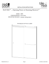
Exploded View drawing of shower door
3/16” Masonry drill bit (use 9/64” drill
bit for fiberglass)
1/8” drill bit
Drill
4’ Level
Saw (Electric Chop saw or Hacksaw)
Side cutting pliers
#2 Phillips drill bit
#2 Phillips screwdriver
Tape Measure
Pencil or Pen
Caulking Gun
1-Tube of 100% Clear Silicone (no latex!)
Vacuum Cleaner or Brush for clean up
Glass Cleaner and Paper Towels
Rubber Mallet
File
Arizona Corporate Office
2801 W. Indian School Rd
Phoenix, AZ 85017
800-255-1901 PH
602-447-8208 FAX
Florida
8100-1 Westside Industrial Dr
Jacksonville, FL 32219
855-695-8899 PH
904-786-9025 FAX
Illinois
2601 Bond St #1
University Park, IL 60484
800-861-6120 PH
708-235-0729 FAX
Oregon
2057 Lars Way
Medford. OR 97501
866-773-7905 PH
541-773-7909 FAX
Colorado
3871 Revere Street
Denver, CO 80239
866-574-1766 PH
303-574-1775 FAX
Utah
2594 S. 3600 West Suite A
West Valley City, UT 84119
877-402-5007 PH
801-972-3111 FAX

1) Find the centerline of where the unit will be
installed. This will usually be the center of the
ledge of the bath tub or the curb of the shower
pan. Place a centerline mark at each end of the
tub ledge or curb where it meets the wall. This
mark will also represent the center of the
ZTE7203 wall jamb (item #4 in exploded view).
Place the wall jamb against the wall and on top
of the ledge or curb aligning centerline marks
(A). If your shower is fiberglass you might have
to file the backside corner of the ZTE7203 to a
radius so the jamb sits as flush as possible on
the ledge or curb. Use a level to position the
jamb plumb, then mark the installation holes
with a pen or pencil
(B). Repeat this procedure
for the other jamb. Now drill the 6 holes with a
3/16” masonry bit (9/64” for fiberglass, & with-
out anchors). Then insert the 6)-ZV935 screw
anchors (#5) in the holes. Fasten the ZTE7203
wall jambs in place using the #8X1-1/4 Phillips
Pan Head screws provided (#6)
(C). Install the
two ZV927 bumpers with the center screws of
the wall jambs. Refer to the exploded view
drawing.
(D). Refer to the exploded view draw-
ing.
Model ETE-3/8 & ESE-3/8
Installation Instructions
for
Note: These instructions will refer to the item #’s in the Exploded View drawing. For example, #1, #2, #3 etc…
Please read through all of the instructions to get an over-view before you install the door.

2) Measure the distance between the inside of
the wall jambs (just above the tub ledge or
curb). Measure tight and deduct 1/16” to 1/8”
to get the cut size of the ZTE7222 Curb (#3)
(E).
Cut to size. Apply silicone where wall jambs
meet tub or curb. Then run a bead along the
underneath of the ZTE7222 Curb
(F). Slide the
curb down between the wall jambs and onto
the tub/shower. Make sure the curb is solid and
doesn’t rock back and forth. If it is not solid se-
cure it with two of the #6X3/8” Pan Head
Screws (#12) provided by drilling with a 1/8”
drill bit through the outside leg of the wall jamb
at the bottom, into the face of the curb and in-
serting the screws
(G).
3) Measure the distance from wall to wall
across the top of the jambs. Cut the ZTE2601A
Header (#8) to that dimension minus -1/16”.
Slide the header down over the top of the wall
jambs. The header does not need to be secured
with screws.
(H)
4) Setting of the glass. The inside panel will be
set first. This will be done as you stand on the
outside of the shower. Grip one of the panels
on each side so that the rollers are facing away
from you. Lift the panel so that the bottom
edge of the glass clears the top of the ZTE7222
Curb as you lower it into the shower. Do not set
the glass down on its edge. Be very careful to
not hit the edge on anything. Continue lower-
ing the panel down

until the top rollers can be guided up into the
inside roller track of the header. Lift up glass
then slowly lower the rollers into the inside
roller track and let the panel hang in its vertical
position. The outside panel will be installed the
same way. Make sure the rollers are facing to-
ward you. A helper would be valuable at this
point to hold the inside panel on an angle to-
ward the inside so that the outside panel can be
lowered and positioned to be installed into the
outside roller track. The inside panel will be po-
sitioned at the showerhead side of the shower
while the outside panel will be positioned op-
posite the showerhead. This is to ensure that no
water escapes through the overlap
(I).
5) Adjust Rollers (J). The roller wheels are
mounted to angled slots in the top rail on the
glass. Lowering the roller in the slot raises the
glass. Raising the roller in the slot lowers the
glass. Start out with the rollers mounted in the
middle of the angled slot. If the panel needs to
be adjusted you can remove the panel, adjust
with a screwdriver then, reset the panel. This
might be done one or two times until you
achieve proper alignment. The end result
should be that the vertical edge of the panel is
parallel to your wall jamb to achieve maximum
coverage.
6)
Attach the ZV975 Center Guide (#11).
Position the guide in the center of the overlap
of the glass. When the doors are in a closed po-
sition the center guide should be centered in
the overlap of the glass. Attach the guide in
place by drilling with a 1/8” drill bit through the
inside leg into the curb(from the inside of the
I
J

shower) then running a #6X3/8 screw into the
hole
(K).
7) *please see attached before proceeding
Attach the ASD-1 (#10) Knob Pull
(L) by insert-
ing the threaded bolt with grommet through
the hole. This will be the inside panel with one
hole which will be on the showerhead side of
the opening. The knob should be on the inside.
Also make sure the plastic washers provided are
on each side of the glass. Use the small Allen
wrench provided to insert into the small hole on
the bolt head. Turn and tighten the bolt until
the knob is secure. Over tightening can cause
the glass to blow up.
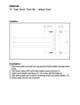
8) Attach the towel bar (M) on the outside
panel with two holes using the same method as
the knob in step 7.
9) Run a bead of silicone on the gap between
the metal and the shower surface inside and
out. Fill all joints and gaps where metal meets
metal and fill with a fine bead.
(N)

*Towel bar and Pull Handle Addendum
Due to design changes in the LETET, LESET, ETE, and ESE Series of bypass shower enclosures. There are
now two separate types of pull handle and towel bars. The (ASD1) pull handle and the (ASD#T) towel bar
are designed for glass with ½” holes. While the (ASD1R) pull handle and (ASD#R) towel bar are designed
for glass with 7/8” holes. While ordering replacement parts please specify hole dimension.(1/2” or 7/8”).
**** # = centerline width of the towel bar (ex: 18”, 24”, and 27”) ****
/