Page is loading ...

RDQCI5301 Rev. 0 Page 1 Cered 11/01/2016
SERIES:
CONFIGURATION:
MOUNTING PACKAGE:
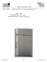
3000
Door-Door
Header, sliding doors
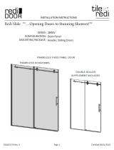
SERIES: 2000
CONFIGURATION: Door-Panel
MOUNTING PACKAGE: No header, glass-to-glass hinges,
u-channel on panel(s) and or return(s)
bottoms, wall clamps on panel(s) and or
return(s) wall sides, support bars from
walls to panels-returns
Redi Swing
TM
...Opening Doors to Stunning Showers!
TM
INSTALLATION INSTRUCTIONS
tile
redi
®
redi
DOOR
®
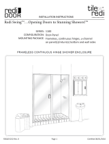
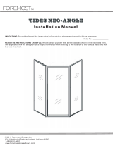
FRAMELESS INLINE DOOR
SERIES: 2000
CONFIGURATION: Door-Panel
MOUNTING PACKAGE: No header, glass-to-glass hinges,
u-channel on panel(s) and or return(s)
bottoms, wall clamps on panel(s) and or
return(s) wall sides, support bars from
walls to panels-returns
Redi Swing
TM
...Opening Doors to Stunning Showers!
TM
INSTALLATION INSTRUCTIONS
tile
redi
®
redi
DOOR
®
FRAMELESS INLINE DOOR
Redi Slide

RDQCI5301 Rev. 0 Page 2 Cered 11/01/2016
Installation Notes:
Proper blocking is required for every Heavy Glass unit prior to installation. At minimum 2x4
blocking is required at the location of any structural member of the unit including, but not lim-
ited to: hinges, clamps, and header brackets. All fasteners at these locations are required to
be installed into the blocking.
A minimum of 1 1/4” thread engagement is required of all fasteners into the blocking at these
locations. Depending on the application the customer maybe required to supply the proper
fasteners to ensure adequate engagement.
U-Channel maybe installed using wall plugs where no backing is found.
Use caution to not pierce plumbing or electric lines while installing door hardware.
Cover the drain with tape prior to installation to prevent loss of small parts.
Unpack your unit carefully and inspect for freight damage. Lay out and identify all parts using
the instruction sheet as a reference. Before discarding the carton, check to see that no small
hardware parts have fallen to the bottom of the box. If any parts are damaged or missing, refer
to the description noted in the instructions when contacting your dealer for replacements.
Maintenance:
Tools:
To install your New Shower Enclosure, you may need the following:
Pencil
Low Tack Tape
Tape Measure
4’ & 6’ Levels
#2 Phillips Screwdriver
Hack Saw
Caulk Gun
Clear Silicone Caulk
Suction Cups
Drill
1/8” & 3/16” Drill Bit
Center Punch
Files
This unit is best installed by two people.
Handle the glass panels carefully and protect the edges. Safety tempered glass is very re-
sistant to breakage, but the sharp corners of the panels can damage tile and flooring surfaces.
The glass can break if unequal pressure is applied during installation.
Please wear safety glasses whenever drilling or cutting. When drilling holes in ceramic tile or
marble, use a center punch and hammer to carefully break the glazed surface to prevent skid-
ding when drilling.
NOTE: Tempered glass cannot be cut.
Safety Notes:
Caring for Redi Clear™ Treated Glass
In order to maintain your ten year warranty, please follow these care instructions:
Once or twice a week, wipe down your shower door to remove body oils, soaps and shampoos from the surfaces.
The glass should be cleaned every few weeks using a damp microfiber cloth and a mild detergent or soap to
remove any soap scum and grime from the glass. Do not use paper towels or any abrasive tool to clean the
surface. The sealed surface is warranted with regular maintenance and without the use of any harsh chemicals or
detergents.
Caring for Non-Treated Glass
After each use, rinse with water and wipe down your enclosure with a soft cloth/towel or squeegee to maintain that
like-new look. The glass should be regularly cleaned using a damp microfiber cloth and a mild detergent or cleaner
to remove any soap scum and grime from the glass. We recommend Lysol Bathroom Cleaner as safe for shower
doors, but please test any commercial cleaning solutions on an inconspicuous area before applying to the entire
enclosure. Be sure to rinse all surfaces completely and wipe dry. Never use any abrasive material or harsh
chemicals to clean surfaces and do not allow cleaners to soak on surfaces.

RDQCI5301 Rev. 0 Page 3 Cered 11/01/2016
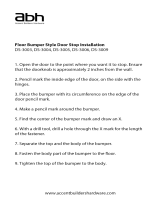
ITEM DESCRIPTION QT Y.
1 OUTER PANEL 1
2 INNER PANEL 1
3 HEADER 1
4 WALL JAMB 2
5 CURB TRACK 1
6 SILENCER VINYL 1
7 ANTI-JUMP RAIL 1
8 TOWEL BAR 1
** PARTS PACK #2
9 TOP ROLLER ASSEMBLY 2
10 BOTTOM ROLLER ASSEMBLY 2
11 BUMPER 4
** PARTS PACK #1
12 WALL MOUNT BRACKET 2
13 TOP ROLLER BACK CAP 2
14 ROLLER FRONT CAP 2
15 BOTTOM GUIDE 1
16 KNOB 1
17 WALL JAMB SCREW, #8 X 1 1/2” SCREW 10
18 GUIDE SCREW, #8 X 2” SCREW 1
19 #8 X 1/4” TRUSS HEAD SCREW, SS 6
## PLASTIC WALL PLUG 8
## 2.5mm ALLEN WRENCH 1
PARTS LIST
** Parts Pack is not shown. The Parts Pack includes required installaon hardware. Depending upon
the exact conguraon of the unit being installed, not all parts maybe used.
## Part is not shown, but is included in Parts Pack #1. These parts will not be used in all instances.

RDQCI5301 Rev. 0 Page 4 Cered 11/01/2016
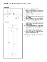
EXPLODED VIEW

RDQCI5301 Rev. 0 Page 5 Cered 11/01/2016
This unit maybe installed with the inner panel to either side.
In order to minimize chances of water leakage, please install the inner panel closest to the shower
head. Installation with the inner panel opposite of the shower head when closed leaves a gap be-
tween the panels that water may pass through.
MINIMUM THRESHOLD WITDH
This unit requires a minimum 2 3/4” threshold width.
SHOWER HEAD
The unit requires 2 3/4” of threshold width to ensure the unit does not hang off of the edge. It is up to
the installer to determine if the threshold is wide enough to drill into so as to not damage the finished
surface. Please take appropriate precautions to be sure tile surfaces are wide enough so that they
are not broken during the installation process.

RDQCI5301 Rev. 0 Page 6 Cered 11/01/2016
DRILLING HOLES
This unit maybe installed on many types of walls. Please reference this section to determine how to
drill holes in your walls based on what material your walls are made of.
Fiberglass Enclosure: Use standard 1/8” drill bit to drill holes through the fiberglass wall mate-
rial at marked locations. Place a small amount of silicone into each hole before installing the screw.
If the fiberglass enclosure will not hold the screw:
Drill a 3/16” hole at the marked location. Insert a small amount of silicone into each hole. Place a
supplied blue wall plug into the hole. With a razor blade, carefully cut the head off of wall plug so it is
flush with the finished wall material.
Tile or Solid Surface with Blocking:
Use a center punch at each marked location to prevent
the drill from walking. Use a 3/16” masonry bit to drill through the finished wall material (tile and
backer board) ONLY. Use a standard 1/8” drill bit to drill 1” deep pilot holes in the blocking. Insert a
small amount of silicone in each hole before installing the screw. 1” thread engagement of screws in
blocking is required. The customer maybe required to supply their own screws based on their fin-
ished wall material thickness.
Tile or Solid Surface without Blocking: Use a center punch at each marked location to
prevent the drill from walking. Use a 3/16” masonry bit to drill through the wall material. Insert a
small amount of silicone into each hole. Place a supplied blue wall plug into the hole. With a razor
blade, carefully cut the head off of wall plug so it is flush with the finished wall material.

RDQCI5301 Rev. 0 Page 7 Cered 11/01/2016
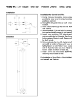
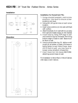
IDENTIFY GLASS PANELS
If the panels have the Redi Clear™ treated glass there will be labels identifying the coated side.
In-stall the panels with the coated side to the inside.
The Inner Panel has 2 mounting
holes lower on the panel and 1
hole for the Knob. The knob
mount hole will be against the
wall when the panel is closed.
The Outer Panel has 2 mounting
holes higher on the panel and 2
holes for the Towel Bar.
WALL

RDQCI5301 Rev. 0 Page 8 Cered 11/01/2016
1 Determine location of the unit centerline on the threshold.
Mark a continuous centerline on both walls starting where the threshold centerline meets the wall.
Use a level to ensure the wall centerline is plumb and straight. The wall centerline should be a mini-
mum of the unit height from the threshold.

RDQCI5301 Rev. 0 Page 9 Cered 11/01/2016
3 Place a Wall Jamb on each wall. Align the Wall Jamb with the marked centerline running
through the pre-drilled holes.
Use a level to confirm the Wall Jamb is plumb. Mark the hole locations.
2 Along the threshold, mark the middle point. This will be the location to install the
center guide.
Centerline visible in pre-drilled
holes of Wall Jamb

RDQCI5301 Rev. 0 Page 10 Cered 11/01/2016
4 Drill the 6 marked locations. Drill holes as described on page 4
5 Set the Wall Jambs in place. Secure
with 6 SCR10 Wall Jamb Screws. Install 4
SC4259 Bumpers, 1 each on top and bot-
tom screws.
If required, be sure to install wall plugs be-
fore securing wall jambs. See page 4

RDQCI5301 Rev. 0 Page 11 Cered 11/01/2016
6 Measure the Wall-to-Wall distance at the top of the Wall Jambs.
Record the measurement [T]:_________”
PRO-TIP: After the header is cut to the proper length (Step 7) it may fit between the wall
jambs at the threshold. This is an excellent straight edge for Step 8.
8 Using a straight edge mark a straight line at the front of the unit as shown. Mark a straight line
flush against the front inside edge of the wall jambs.
This will ensure the curb is installed without any bows that would impede proper glass movement.
Pull the straight edge ght against the inside
edge of the Wall Jamb. Use a pencil to trace the
outside edge onto the threshold.
7 Subtract 1/2” from the measurement [T]. [T] - 1/2” = _____________” [HC]
Cut the Header to length [HC].

RDQCI5301 Rev. 0 Page 12 Cered 11/01/2016
10 Lower the Header Assem-
bly into the Wall Jambs, being
sure the Header Mount Brack-
ets slide into the grooves of the
Wall Jamb. Rest the Header As-
sembly on the top Bumpers.
9 Slide the Header Mount Brackets into each side of the Header. Temporarily tighten the mount
screw on one side.
This is now the
Header Assembly.
Header Assembly
Rests on Top
Bumpers

RDQCI5301 Rev. 0 Page 13 Cered 11/01/2016
11 Use a 4’ level to check the Header As-
sembly for level. To level the header, lift on-
ly 1 side from the Top Bumper. Mark the
location of the Header Mount Brackets on
the Wall Jambs.
12 Remove the Header Assembly from the Wall Jambs.
Remove the Header Mount Bracket from the Header that was not tightened in Step 9
Loose Header Mount
Bracket from Step 9

RDQCI5301 Rev. 0 Page 14 Cered 11/01/2016
13 Slide the Header
Mount Brackets into each
Wall Jamb. The 3 holes
face Inside the Shower.
Align the Header Mount
Brackets with the mark
made in STEP 11. Mark the
locations of the mounting
slots as shown.
14 Remove the Header Mount Brackets and drill 1/8” holes at the 4 marked locations. Drill only
through the aluminum Wall Jamb.
Mark from Step 11
15 For easier installation of the Header Assembly, install and then remove the 4 SCR02 Header
Mount Screws.
DO NOT use a power tool to prevent stripping the holes.
PRO-TIP: This step pre-
threads the mounting holes to
make final installation easier.
For even easier installation, a
small amount of candle wax
or bar soap on the threads will
make installation of the screw
easier and will help prevent
stripping the head.
Be sure the mounng
holes are to the inside
of the shower
PRO-TIP: Make the holes near the
top of the adjustment slots. If they
are drilled accurately this will pre-
vent the header from slipping out of
adjustment in the future.

RDQCI5301 Rev. 0 Page 15 Cered 11/01/2016
17 Install the SCR02 Header Mount
Screws from STEP 15. Re-check the
header for level. Make any final adjust-
ments and secure the screws.
DO NOT use a power tool
to prevent stripping the
holes.
16 Reassemble the Header and Header Mount Brackets. Re-insert the Header Assembly
into the Wall Jambs.

RDQCI5301 Rev. 0 Page 16 Cered 11/01/2016
20 If the Silencer Vinyl was not already inserted, slide the SCV190 Silencer Vinyl into the Track.
Trim to length. This is the Track Assembly.
18 Using the provided Allen Wrench, tighten both Header
Set Screws.
19 Measure the Threshold Width [TW]: __________
SUBTRACT 5/8”
Cut the Curb Length [CL] to:___________

RDQCI5301 Rev. 0 Page 17 Cered 11/01/2016
22 While keeping the
Track Assembly
straight and on the line,
position the Center
Guide. It locks into the
Track Assembly and
the mounting hole
should be centered on
the line marked in Step
2. Mark the mounting
screw location.
21 Position the Track Assembly on the threshold with the front edge on the line marked in Step
8. The front of the track will contact the front inside edge of each wall jamb.
Use a pencil to mark both inside and outside edges of the curb.

RDQCI5301 Rev. 0 Page 18 Cered 11/01/2016
23 Remove the Track Assembly and Center Guide. Drill hole as described on page 4 at the
marked location.
24 Apply a 3/16” bead of silicone to the threshold between the lines marked to identify the inside
and outside edge of the Track Assembly. Carefully put the Track Assembly into place on the
threshold. Use masking tape near the ends of the Track Assembly to keep it positioned on the
threshold while the silicone cures.

RDQCI5301 Rev. 0 Page 19 Cered 11/01/2016
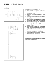
25 Install the rollers on the outer panel.
The rollers will be on the inside of the
shower.
-The rollers are mounted to adjustable
cams. Install them with the rollers at the
lowest position.
-Temporarily install the anti-jumps parallel
to the floor.
-Only snug the screws for now.
NOTE: There are small part numbers on
each part of the roller. All of them will
face the glass.
26 Install the rollers on the inner
panel. The rollers will be on the out-
side of the shower.
-The rollers are mounted to adjusta-
ble cams. Install them with the roll-
ers at the lowest position.
-Only snug the screws for now.
NOTE: There are small part num-
bers on each part of the roller. All
of them will face the glass.

RDQCI5301 Rev. 0 Page 20 Cered 11/01/2016
28 Lift the Outer Panel Assembly into
place. Set the rollers in their grooves on the
top of the header. Make sure the glass is in-
side the lip on the track. It is easiest to set the
glass near the middle of the header.
The glass is not secure yet. Do not leave
unattended. Moving it may cause the glass
to fall.
27 To prevent scratching the header during glass installation, apply masking tape to the front face
of the header.
Place the Inner panel inside the shower, but DO NOT hang it. Protect the glass from contacting hard
surfaces.
29 Insert a small amount of Silicone into the hole of the guide. Mount the Center Guide into the
drilled hole using the supplied 2” Guide Screw.
Be sure to align the guide with the track.
/