Page is loading ...


Tools you will need for this install
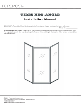
Exploded View drawing of shower door
3/16” Masonry drill bit (use 9/64” drill
bit for fiberglass)
1/8” drill bit
Drill
4’ Level
Saw (Electric Chop saw or Hacksaw)
Side cutting pliers
#2 Phillips drill bit
#2 Phillips screwdriver
Tape Measure
Pencil or Pen
Caulking Gun
1-Tube of 100% Clear Silicone (no latex!)
Vacuum Cleaner or Brush for clean up
Glass Cleaner and Paper Towels
Rubber Mallet
File
Arizona Corporate Office
2801 W. Indian School Rd
Phoenix, AZ 85017
800-255-1901 PH
602-447-8208 FAX
Florida
8100-1 Westside Industrial Dr
Jacksonville, FL 32219
855-695-8899 PH
904-786-9025 FAX
Illinois
2601 Bond St #1
University Park, IL 60484
800-861-6120 PH
708-235-0729 FAX
Oregon
2057 Lars Way
Medford. OR 97501
866-773-7905 PH
541-773-7909 FAX
Colorado
3871 Revere Street
Denver, CO 80239
866-574-1766 PH
303-574-1775 FAX
Utah
2594 S. 3600 West Suite A
West Valley City, UT 84119
877-402-5007 PH
801-972-3111 FAX

1) Find the centerline of where the unit will be
installed. This will usually be the center of the
curb of the shower pan. Place a mark 1/2” inch
to the outside of centerline at each end of the
curb where it meets the wall and at the corner.
These marks will represent the outside of the
ZSS-2101 Curbs (item #2 in exploded view)
(A).
Use the centerline measurements that were
given at the time of order to figure your ZSS-
2101 sizes. Take the centerline measurements
and add 1/4” to get the outside dimension of
each ZSS-2101. Measure from the outside edge
of the mitered corner, along the outside of the
ZSS-2101 to the correct dimension and cut to
size. Repeat this procedure for the other ZSS-
2101 Curb
(B). Lay the curbs on drop cloth or
carpet to prevent from scratching them. As-
semble the curbs on the floor using the ZH135
135˚ degree Header Bracket (#20) and the
#8X1/4” Header Curb Bracket Screws (#21). As
the curbs are lying open end down, place the
ZH135 bracket onto the corners and align the
miters, corner bracket, and holes. Fasten the
corners together with the #8x1/4”
Installation Instructions for
Model CDFMP-135
Note:
These instructions will refer to the item #’s in the Exploded View drawing. For example, #1, #2, #3 etc…
Please read through all of the instructions to get an over-view before you install the shower door.

screws and then place the assembled Curb in
the position laid out on the shower curb corres-
ponding to the marks that you made. Make sure
to fill the corners where the screws were in-
serted and the ends with silicone so as to seal
any gaps that might leak but do this after the
wall jams are installed
(C).
2) Place a Wall Jamb ZD-1006 (#3) against the
wall and down into the Curb. Use a level to po-
sition the jamb plumb, then mark the installa-
tion holes with a pen or pencil. Repeat this pro-
cedure for the other jamb
(D). Now drill the 6
holes with a 3/16” masonry bit (9/64” for fiber-
glass, & without anchors). Then insert the 6)-
ZV935 screw anchors (#15) in the holes. Fasten
the ZD-1006 wall jambs in place using the #8X1-
1/4 Phillips Pan Head screws provided (#14).
Fill the corner inside the ZSS-2101 to protect
against water leaks
(E).
3) Place two Setting Blocks ZV902 (#13) into
the Curb on the side where your panel will be.
Insert the Glass into the ZSS-2101Curb and the
ZD-1006 Wall Jamb.
Insert the 135 Post ZSS-
1105 (#19) into the Curb and onto the edge of
the glass
(F).
4) Plumb your ZSS-1105 135° corner post.
Measure from the wall above the ZD-1006 Wall
Jamb over the glass to the outside and to the
center of the ZSS-1105 135° post. Add 1/8” to
the measurement then mark the header at that
dimension and cut. Repeat the procedure for
the other ZSS-2101 Header
(G).

5) Assemble the Header on the floor (like pre-
viously on the Curb) using the ZH135 135 de-
gree Header Bracket (#20) and the #8X1/4”
Header Curb Bracket Screws (#21). As the head-
ers are lying open end down, place the ZH135
Bracket onto the corner and align the miters,
corner bracket, and holes. Fasten the corner
together with the #8x1/4” screws (refer to
(C)).
Now place the assembled header pieces over
and down onto the vertical posts. Attach the
Header to the Wall Jambs and 135° Post from
the inside using a 1/8” drill bit to drill through
the header and into the wall jambs and 135°
Post being extremely careful not to drill into
the glass. Secure with the #6X3/8” screws (#16)
(H). Insert the ZV909 Wedge Vinyl (#18) into
the jambs on both sides of the glass. A block of
wood will help push the vinyl in. Slightly wet the
vinyl with water to ease install. The flat side
goes against the glass. Notice the locking
groove
(I). Insert the ZV906 Horizontal Wedge
Vinyl into the header and curb (#17) in between
the metal and glass without stretching it, both
inside and out, top and bottom. Notice the lock-
ing groove
(J).
6) Now you need to cut the Snap In Fillers ZSS-
1102 (#4). Measure from inside edge of the ZSS-
1105 to inside edge of the ZD-1006 (the daylight
door opening). Cut the fillers to these dimen-
sions. Snap the fillers into the ZSS-2101’s top
and bottom. There is a small lip on the filler.
This faces to the outside of the unit
(K).
7) Hang the door. Slide the ZD-8004 Magnetic
Latch Jamb (#11) over the wall jamb or corner
post, whichever side the door will latch on. In-
stall the door by sliding the ZD-2505A Door

Hinge Jamb (#5) over the hinge side post or
jamb. Do not fasten the door at this point
(L).
8) Inspect and fit the magnetic strip to figure
out the side that will attract and not repel. In-
stall the side that repels against the high bond
tape that you will install. Attach the full length
ZV987 Magnetic Strip by applying the clear high
bond tape along the inside of the door and
aligning it with the edge of the glass, insetting
about 1/16”. Put it on all the way down until it
touches the ZD-1002. Cut here then remove
protective layer off tape. Apply the magnetic
strip to the tape in the same fashion by gradual-
ly unrolling until it reaches the bottom rail. Cut
to fit
(M).
9) Note: (It will be helpful to have an assistant
at this point to adjust and hold the door in place
from the outside while you drill and fasten the
latch jamb and the hinge jamb from the inside).
Square up the door and align the two magnetic
strips until they make a strong seal. Attach the
door by drilling the six holes on the inside of the
unit where the jambs are pre-drilled using an
1/8” drill bit and secure with the 6-#6X3/8” Pan
Head screws (#8)
(N).
10) Attach the ASD 8X8 Handle (#28). Take the
two stud head mounting screws and sleeve one
clear washer on each screw. Next, insert the
clear grommets into the holes in the door. From
the outside of the door, push the thread of the
screws through the grommets in the holes in
the glass. On the inside of the door, sleeve a
clear washer onto the screws. Take the pull that
has the threaded hole in the end and begin to
thread the top screw into it and then the bot-

tom screw. Tighten the stud head screws down
with a screwdriver (not a drill). This pull will be
on the inside of the door. Place the remaining
pull, with the large holes and set screw, onto
the stud heads of the screws. Tighten the set
screws with Allen wrench provided
(O).
11) Adjust ZD-2008 Drip Trough (#12) on door
to slope towards the hinge
(P).
12)
Run a bead of silicone on the gap between
the metal and the shower surface inside and
out around the entire unit. Fill all joints and
gaps where metal meets metal and fill with a
fine bead
(Q).
/