Page is loading ...

RDQCI5017 Rev. 0 Page 1 Cered 06/01/2016
SERIES:
CONFIGURATION:
MOUNTING PACKAGE:
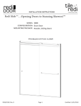
2000
Door-Door
Frameless Sliding Door

RDQCI5017 Rev. 0 Page 2 Cered 06/01/2016
Installation Notes:
Proper blocking is required for every Heavy Glass unit prior to installation. At minimum 2x4
blocking is required at the location of any structural member of the unit including, but not lim-
ited to: hinges, clamps, and header brackets. All fasteners at these locations are required to
be installed into the blocking.
A minimum of 1 1/4” thread engagement is required of all fasteners into the blocking at these
locations. Depending on the application the customer maybe required to supply the proper
fasteners to ensure adequate engagement.
U-Channel maybe installed using wall plugs where no backing is found.
Use caution to not pierce plumbing or electric lines while installing door hardware.
Cover the drain with tape prior to installation to prevent loss of small parts.
Unpack your unit carefully and inspect for freight damage. Lay out and identify all parts using
the instruction sheet as a reference. Before discarding the carton, check to see that no small
hardware parts have fallen to the bottom of the box. If any parts are damaged or missing, refer
to the description noted in the instructions when contacting your dealer for replacements.
Maintenance:
Tools:
To install your New Shower Enclosure, you may need the following:
Pencil
Low Tack Tape
Tape Measure
4’ & 6’ Levels
#2 Phillips Screwdriver
Hack Saw
Caulk Gun
Clear Silicone Caulk
Suction Cups
Drill
1/8” & 3/16” Drill Bit
Center Punch
Files
This unit is best installed by two people.
Handle the glass panels carefully and protect the edges. Safety tempered glass is very re-
sistant to breakage, but the sharp corners of the panels can damage tile and flooring surfaces.
The glass can break if unequal pressure is applied during installation.
Please wear safety glasses whenever drilling or cutting. When drilling holes in ceramic tile or
marble, use a center punch and hammer to carefully break the glazed surface to prevent skid-
ding when drilling.
NOTE: Tempered glass cannot be cut.
Safety Notes:
Caring for Redi Clear™ Treated Glass
In order to maintain your ten year warranty, please follow these care instructions:
Once or twice a week, wipe down your shower door to remove body oils, soaps and shampoos from the surfaces.
The glass should be cleaned every few weeks using a damp microfiber cloth and a mild detergent or soap to
remove any soap scum and grime from the glass. Do not use paper towels or any abrasive tool to clean the
surface. The sealed surface is warranted with regular maintenance and without the use of any harsh chemicals or
detergents.
Caring for Non-Treated Glass
After each use, rinse with water and wipe down your enclosure with a soft cloth/towel or squeegee to maintain that
like-new look. The glass should be regularly cleaned using a damp microfiber cloth and a mild detergent or cleaner
to remove any soap scum and grime from the glass. We recommend Lysol Bathroom Cleaner as safe for shower
doors, but please test any commercial cleaning solutions on an inconspicuous area before applying to the entire
enclosure. Be sure to rinse all surfaces completely and wipe dry. Never use any abrasive material or harsh
chemicals to clean surfaces and do not allow cleaners to soak on surfaces.

RDQCI5017 Rev. 0 Page 3 Cered 06/01/2016
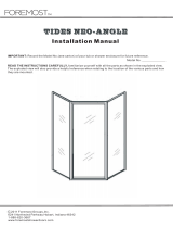
ITEM DESCRIPTION QT Y.
A Wall Jamb 2
B boom Track (w/ Silencer) 1
C Plasc Wall Anchor 6
D #8 x 1 1/2” Truss Head Screws 6
E Clear Jamb Bumper 6
F Nylon T-Lock 2
G Header 1
H Hanger Bracket (Pre-Aatched) 4
J Glass Door Panel 2
K Glass Hole Sleeve 4
M Heavy Glass Roller 4
N #8-32 x 3/8” Roller Screw 4
P Back Plate 4
R Clear Plasc Disc 8
S Front Plate
U Towel Bar 2
V Boom Guide 3
W #6 x 3/8” Pan Head Screw 3
X Nylon Jamb Cover 2
PARTS LIST
*Quanes may vary.
**Support bar only included if necessary.

RDQCI5017 Rev. 0 Page 4 Cered 06/01/2016
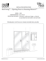
EXPLODED VIEW

RDQCI5017 Rev. 0 Page 5 Cered 06/01/2016
SHOWER HEAD LEFT SHOWER HEAD RIGHT
EXTERIOR
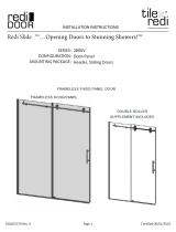
1 This framess bypass sliding enclosure
is supplied with pocketed wall jambs [A]. The
jambs are notched on both ends to fit over the
bottom track. It is important to determine the proper
orientation of the unit before marking and drilling
the walls. For maximum waterproofing, position
the “open” pocket of the wall jamb to the interior
for the shower head wall. This will force the interior
panel to be on the shower head side. (see illustration)
2 Measure the wall-to-wall opening along the
center of the threshold at the bottom. Cut the bottom
track (w/ vinyl silencer) [B] 1/16” short of that
dimension.
Position the bottom track in the center of the threshold
with the raised edge to the exterior. It may be necessary
to file a radius on the ends of the track and wall jambs
to match the corners of the opening.
3 Place one wall jamb over the track and against
the wall. Using a level, plumb the wall jamb and mark the
hole locations on the wall with a pencil. Repeat this step
for the other wall jamb. (Be sure that the curb does not move)
Mark along both inside and outside of the track.
Remove all parts and drill the holes.
Tile, marble or solid surface walls:
Drill 3/16” diameter holes into the walls and insert the
plastic wall anchors [C].
Fiberglass or acrylic units can be done two different ways:
If the walls are not reinforced, drill 3/16” diameter holes
and insert the plastic wall anchors. (Toggle bolts may
be used instead but they are not provided).
If the walls are reinforced, only drill 1/8” diameter holes.
RDQCI5017 Rev. 0 Page 4 of 8 Certified 06/20/16

RDQCI5017 Rev. 0 Page 6 Cered 06/01/2016
Interior
SILICONE
RDQCI5017 Rev. 0 Page 5 of 8 Certified 06/20/16
4 Before replacing the track, force a slight
downward bow into it. This will ensure that the
track fits tight to the threshold in the middle.
Run a bead of silicone on both flat surfaces on the
bottom of the track. Then replace the track onto the
threshold using the pencil marks from step #3 as a
guide. Be sure the raised side is on the exterior.
5 Replace one wall jamb and attach it to the wall with
the #8 x 1 1/2” truss head screws [D]. Check the wall jamb
for plumb and tighten the screws.
Repeat for the other wall jamb.
NOTE: Careful not to overtighten.
Peel the backing from four of the clear jamb bumpers [E]
and attach them inside the pockets of the wall jambs. Place
the bumpers approximately 1” above the bottom screw and
1” below the top screw.
6 This enclosure is equipped with molded nylon
T-Locks [F] for safety. When properly installed, the header
is locked to the wall jambs and cannot be accidently removed.
Measure the wall-to-wall opening at the top of the wall jambs.
Cut the header 1/16” short of that dimension. Check for fit.
TIP: Use a miter box to ensure a straight cut
Slide one of the T-Locks into one end of the header. Set the
header down onto the wall jamb with the T-Lock fitting into
the space behind the wall jamb. Remove the top truss head
screw. Pull the header and T-Lock down until the truss head
screw can be replaced.
Repeat for the other T-Lock.

RDQCI5017 Rev. 0 Page 7 Cered 06/01/2016
EXTERIOR
EXTERIOR
7 Attach the four black heavy-duty roller bearings [M]
to the door hanger brackets [H] as shown using the #8-32 x 3/8”
hex head screws [N]. The rollers should be approximately in the
center of the slots of the bracket fins.
8 Place one panel [J] on the inside of the shower/tub with the
rollers facing the back wall and the textured side of the panel
facing the outside (if applicable). Set it on a drop cloth or piece
of cardboard to protect the glass and the shower/tub surface.
From the outside of the shower/tub, grab the other panel with the
rollers (and textured side of glass) facing you and lift the panel.
Lower it into the shower/tub and then lift it into the header. Be
sure the bracket fins and rollers are above the track groove.
Carefully lower the panel until the rollers are seated into the groove.
Slide the panel to one side and step inside the shower/tub and
step inside. Repeat the previous steps for the inside panel.
Check for alignment along the bottom and sides of each panel
and adjust the rollers as necessary.
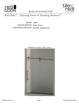
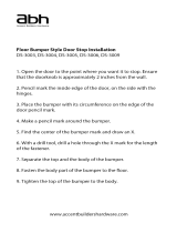
9 Slide one of the clear plastic discs [R], then
a glass hole sleeve [K] onto the threaded back plate [P].
Push the assembly through the hole in the glass panel
so that the glass hole sleeve is flush with the other side
of the panel. Slide the other clear plastic disc onto the
protruding threaded part of the back plate, and then
slide on the front plate [S]. Repeat this for the second
hole on the panel. While holding the towel bar [U] in
place, and screw the back plates into the towel bar. Use
the provided Allen wrench and the small hole drilled into
the side of the back plate to fully tighten the towel bars.
NOTE: Outer panel has towel bar facing Out.
Inner panel has towel bar facing In.
Refer to the diagram in step #1.
U
S
R
P
R
K
RDQCI5017 Rev. 0 Page 6 of 8 Certified 06/20/16

RDQCI5017 Rev. 0 Page 8 Cered 06/01/2016
10 Place one of the clear bottom guides [V]
in the middle of the tub track as shown. Using
the hole in the back of the bottom guide, drill a
1/8” hole into the inside of the tub track.
Attach the bottom guide with a #6 x 3/8” pan
head screw [W].
Exterior
11 Remove the protective backing from the two
squares of tape on the back side of the nylon jamb
covers [X]. Place the jamb covers against the wall jambs
over the notches of the wall jambs at the top, inside of
the header. Press in place.
12 Peel the backing from two of the clear jamb
bumpers [E] and place them against the wall jambs
on the outside of the pockets, one on each wall jamb.
Press them into place approximately in the vertical
center of each wall jamb.
EXTERIOR
NOTE: The placement of these final two clear
jamb bumpers may vary depending on
any out-of-plumb conditions that may
exist. Adjust accordingly.
RDQCI5017 Rev. 0 Page 7 of 8 Certified 06/20/16

RDQCI5017 Rev. 0 Page 9 Cered 06/01/2016
RDQCI5017 Rev. 0 Page 8 of 8 Certified 06/20/16
SILICONE
SILICONE
13 Neatly silicone each end of the tub track
where it fits into the wall jambs as well as the
seam between the wall and the wall jamb and the
curb and threshold on the inside of the shower.
NOTE: DO NOT USE the shower until the
silicone is completely cured. Check
the tube of silicone for the manufacturer
recommended cure time.
(typically 24 - 48 hours)
NOTE: Silicone on the exterior seam is optional.

RDQCI5017 Rev. 0 Page 10 Cered 06/01/2016
Tile Ready® Brand Shower Pan Installaon Addendum
SPECIAL INSTRUCTIONS FOR REDI DOOR® ENCLOSURE INSTALLATIONS WITH TILE READY® BRAND SHOWER
PANS
Designated screw pack for Tile Ready® Brand Shower Pans:
For Redi Door® enclosure installaons with a Tile Ready® brand shower pan, a special screw pack containing
eight (8) #8x¾” pan-head screws is included with your door. These #8x¾”screws replace curb screws included
in the main hardware package, and their use is mandatory. Set drill stop at 5/8” to avoid piercing the shower
pan curb.
FAILURE TO USE THE CORRECT SCREWS & FOLLOW THESE INSTRUCTIONS WILL VOID THE TILE READY® BRAND
SHOWER PAN LIMITED WARRANTY.
1. Align the u-channel in the proper posion on the curb/entrance
2. Mark and drill a 3/16” hole through the u-channel
3. Transfer this locaon to the le and drill a 3/16” hole through the le and grout only 4. Insert a dab of
silicone caulking into the hole
5. Put the u-channel in place.
6. Using the provided #8 x ¾” pan-head screw, fasten the u-channel in place on the curb.
Special instrucons for Tile Ready® Brand Barrier Free entrances:
For Redi Door® enclosure installaons on a Tile Ready® brand BARRIER FREE entrance, only silicone seal should
be used to aach enclosure parts to the shower pan entrance. No screws or nails should be used to install
enclosure hardware into the shower pan entrance.
THE USE OF SCREWS OR NAILS IN THE BARRIER FREE ENTRANCE WILL VOID THE TILE READY® BRAND SHOWER
PAN LIMITED WARRANTY.
/