Unbranded RTLA05A5976XPSV Installation guide
- Type
- Installation guide

QCI5301 Rev 1 Page 1 Cered 6/5/2017
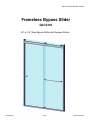
Frameless Bypass Slider
QCI-5301
3/8” or 1/4” Glass Bypass Slider with Exposed Rollers
INSTALLATION INSTRUCTIONS

QCI5301 Rev 1 Page 2 Cered 6/5/2017
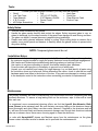
Installation Notes:
A minimum of 1” thread engagement is required of all fasteners. Depending on the application
the customer maybe required to supply the proper fasteners to ensure adequate engagement.
Wall Jambs and Guide maybe installed using wall plugs where no backing is found.
Use caution to not pierce plumbing or electric lines while installing door hardware.
Cover the drain with tape prior to installation to prevent loss of small parts.
Unpack your unit carefully and inspect for freight damage. Lay out and identify all parts using
the instruction sheet as a reference. Before discarding the carton, check to see that no small
hardware parts have fallen to the bottom of the box. If any parts are damaged or missing, refer
to the description noted in the instructions when contacting your dealer for replacements.
Maintenance:
Two primary materials are used to manufacture your new shower enclosure: tempered glass and
anodized aluminum. To assure a long lasting finish on the enclosure, wipe it down with a towel
after each use.
For occasional, more concentrated cleaning efforts, we find that Lysol® Non-Abrasive Bath-
room Cleaner works extremely well. Be sure that any over spray falling on the aluminum frame is
rinsed thoroughly and dried. Many over-the-counter cleaners, if applied to the aluminum and left
on, will harm the metal finish and cause permanent damage even though their directions indicate
safe use on shower doors. Never use a scouring agent to clean the aluminum.
For units with AquaglideXP please use Maintain spray from the maintenance on the glass.
Please contact customer service for details and to purchase the maintenance kit.
Tools:
To install your New Shower Enclosure, you may need the following:
Pencil
Low Tack Tape
Tape Measure
4’ & 6’ Levels
#2 Phillips Screwdriver
Hack Saw
Caulk Gun
Clear Silicone Caulk
Suction Cups
Drill
1/8” & 3/16” Drill Bit
3/16” Masonry Drill Bit
Center Punch
Files
This unit is best installed by two people.
Handle the glass panels carefully and protect the edges. Safety tempered glass is very re-
sistant to breakage, but the sharp corners of the panels can damage tile and flooring surfaces.
The glass can break if unequal pressure is applied during installation.
Please wear safety glasses whenever drilling or cutting. When drilling holes in ceramic tile or
marble, use a center punch and hammer to carefully break the glazed surface to prevent skid-
ding when drilling.
NOTE: Tempered glass cannot be cut.
Safety Notes:

QCI5301 Rev 1 Page 3 Cered 6/5/2017
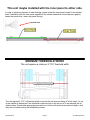
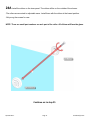
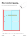
This unit maybe installed with the inner panel to either side.
In order to minimize chances of water leakage, please install the inner panel closest to the shower
head. Installation with the inner panel opposite of the shower head when closed leaves a gap be-
tween the panels that water may pass through.
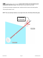
MINIMUM THRESHOLD WITDH
This unit requires a minimum 2 7/16” threshold width.
SHOWER HEAD
The unit requires 2 7/16” of threshold width to ensure the unit does not hang off of the edge. It is up
to the installer to determine if the threshold is wide enough to drill into so as to not damage the fin-
ished surface. Please take appropriate precautions to be sure tile surfaces are wide enough so that
they are not broken during the installation process.

QCI5301 Rev 1 Page 4 Cered 6/5/2017
DRILLING HOLES
This unit maybe installed on many types of walls. Please reference this section to determine how to
drill holes in your walls based on what material your walls are made of.
Fiberglass Enclosure: Use standard 1/8” drill bit to drill holes through the fiberglass wall mate-
rial at marked locations. Place a small amount of silicone into each hole before installing the screw.
If the fiberglass enclosure will not hold the screw:
Drill a 3/16” hole at the marked location. Insert a small amount of silicone into each hole. Place a
supplied blue wall plug into the hole. With a razor blade, carefully cut the head off of wall plug so it is
flush with the finished wall material.
Tile or Solid Surface with Blocking: Use a center punch at each marked location to prevent
the drill from walking. Use a 3/16” masonry bit to drill through the finished wall material (tile and
backer board) ONLY. Use a standard 1/8” drill bit to drill 1” deep pilot holes in the blocking. Insert a
small amount of silicone in each hole before installing the screw. 1” thread engagement of screws in
blocking is required. The customer maybe required to supply their own screws based on their fin-
ished wall material thickness.
Tile or Solid Surface without Blocking: Use a center punch at each marked location to
prevent the drill from walking. Use a 3/16” masonry bit to drill through the wall material. Insert a
small amount of silicone into each hole. Place a supplied blue wall plug into the hole. With a razor
blade, carefully cut the head off of wall plug so it is flush with the finished wall material.

QCI5301 Rev 1 Page 5 Cered 6/5/2017
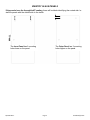
IDENTIFY GLASS PANELS
If the panels have the Aquaglide XP coating, there will be labels identifying the coated side. In-
stall the panels with the coated side to the inside.
The Inner Panel has 2 mounting
holes lower on the panel.
The Outer Panel has 2 mounting
holes higher on the panel.
WALL

QCI5301 Rev 1 Page 6 Cered 6/5/2017
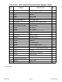
Parts List—3/8” Glass Exposed Roller Bypass Slider
** Part is not shown
ITEM
NO.
NUMBER DESCRIPTION QTY.
1 GLASS PANEL, OUTER 1
2 GLASS PANEL, INNER 1
3 SC923 HEADER 1
4 SC926 WALL JAMB 2
5 SC931 TRACK 1
6 LV09350060XBK00 ANTI-JUMP RAIL 1
7 SCV190-60 SILENCER TUB TRACK, VINYL 1
PPRRTL01SV, OR, BN PARTS PAK #1
8 SC4251 CAP, BACK 2
9 SC4250 CAP, FRONT 4
10 SC4253 WALL MOUNT BRACKET 2
PPRTL03XX PARTS PAK #3
11 SC4249T ROLLER, TOP 2
12 SC4249B ROLLER, BOTTOM 2
13 SC4259 BUMPER 4
14 SC8954 BOTTOM GUIDE 1
15** SC4106 PLASTIC WALL PLUG 10
16 SCR02 #8 X 1/4 TRUSS HEAD SCREW 6
17 SCR10 #8 x 1-1/2" TRUSS HEAD SCREW 10
18 SCR30 #8 x 3/8" 4
19** SC5116 2.5mm ALLEN WRENCH 1
20 SCV960 HOLD DOWN 2
AVAILABLE HARDWARE
21 TB44xx TOWEL BAR 1
22 KBCS-50AI KNOB 1

QCI5301 Rev 1 Page 7 Cered 6/5/2017
Exploded View—3/8” Glass Exposed Roller Bypass Slider
1
2
3
4
4
5
6
7
8
9
9
10
10
11
12
13
13
13
13
14
16
16
17
17
17
17
17
17
18
18
18
20
20
22
21

QCI5301 Rev 1 Page 8 Cered 6/5/2017
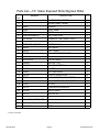
Parts List—1/4” Glass Exposed Roller Bypass Slider
** Part is not shown
ITEM
NO.
NUMBER DESCRIPTION QTY.
1 GLASS PANEL, OUTER 1
2 GLASS PANEL, INNER 1
3 SC923 HEADER 1
4 SC926 WALL JAMB 2
5 SC931 TRACK 1
6 LV09350060XBK00 ANTI-JUMP RAIL 1
7 SCV190-60 SILENCER TUB TRACK, VINYL 1
PPRTL01SV, OR, BN PARTS PAK #1
8 SC4251 CAP, BACK 2
9 SC4250 CAP, FRONT 4
10 SC4253 WALL MOUNT BRACKET 2
PPRTL02XX PARTS PAK #2
11 SC4249T ROLLER, TOP 2
12 SC4249B ROLLER, BOTTOM 2
13 SC4259 BUMPER 4
14 SC8953 BOTTOM GUIDE 1
15 SC4106 PLASTIC WALL PLUG 10
16 SCR02 #8 X 1/4 TRUSS HEAD SCREW 6
17 SCR10 #8 x 1-1/2" TRUSS HEAD SCREW 10
18 SCR30 #8 x 3/8" 4
19** SC5116 2.5mm ALLEN WRENCH 1
20 SCV960 HOLD DOWN 2
21** SC5118 M5-0.8 X 25 2
AVAILABLE HARDWARE
22 TB44xx TOWEL BAR 1
23 KBCS-50AI KNOB 1

QCI5301 Rev 1 Page 9 Cered 6/5/2017
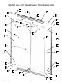
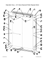
Exploded View—1/4” Glass Exposed Roller Bypass Slider
1
2
3
4
4
5
6
7
8
9
9
10
10
11
12
13
13
13
13
14
15
15
15
15
15
15
16
16
17
17
17
17
17
17
18
18
18
20
20
23
22

QCI5301 Rev 1 Page 10 Cered 6/5/2017
1 Determine location of the unit centerline on the threshold.
Mark a continuous centerline on both walls starting where the threshold centerline meets the wall.
Use a level to ensure the wall centerline is plumb and straight. The wall centerline should be a mini-
mum of the unit height from the threshold.

QCI5301 Rev 1 Page 11 Cered 6/5/2017
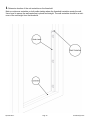
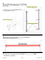
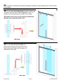
2 Place a Wall Jamb on each wall. Align the Wall Jamb with the marked centerline running
through the pre-drilled holes.
Use a level to confirm the Wall Jamb is plumb. Mark the hole locations.
If custom size door, make sure the correct end of the wall jamb is towards the top. The correct top-
side will have the hole 4-7/16” from the edge.
Centerline visible in pre-drilled
holes of Wall Jamb
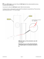
PRO-TIP: The top of the wall jambs come with
round edges.
Depending how your wall and threshold meet,
you maybe required to modify the wall jamb to
fit.

QCI5301 Rev 1 Page 12 Cered 6/5/2017
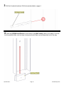
3 Drill the 6 marked locations. Drill holes as described on page 4
4 Insert the SCV960 Hold Downs on the bottom of the Wall Jambs, slide it up to about 1 inch be-
low the predrilled hole, and use tape to temporarily hold them up and keep them out of the way.

QCI5301 Rev 1 Page 13 Cered 6/5/2017
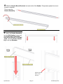
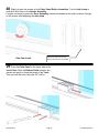
6 Measure the Wall-to-Wall distance at the top of the Wall Jambs.
Record the measurement [T]:_________”
7 Subtract 1/2” from the measurement [T]. [T] - 1/2” = _____________” [HC]
Cut the Header to length [HC].
5 Set the Wall Jambs in place. Secure with 6 SCR10 Wall
Jamb Screws. Install 4 SC4259 Bumpers, 1 each on top and
bottom screws.
If required, be sure to install wall plugs before se-
curing wall jambs. See page 4

QCI5301 Rev 1 Page 14 Cered 6/5/2017
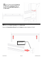
9 Lower the Header Assembly
into the Wall Jambs, being sure
the Header Mount Brackets
slide into the grooves of the Wall
Jamb. Rest the Header Assem-
bly on the top Bumpers.
8 Slide the Header Mount Brackets into each side of the Header. Temporarily tighten the mount
screw on one side.
This is now the
Header Assembly.
Header Assembly
Rests on Top
Bumpers

QCI5301 Rev 1 Page 15 Cered 6/5/2017
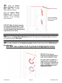
10 Use a 4’ level to check the Header As-
sembly for level. To level the header, lift on-
ly 1 side from the Top Bumper. Mark the
location of the Header Mount Brackets on
the Wall Jambs.
11 Remove the Header Assembly from the Wall Jambs.
Remove the Header Mount Bracket from the Header that was not tightened in Step 8
Loosen Header Mount
Bracket from Step 8

QCI5301 Rev 1 Page 16 Cered 6/5/2017
12 Slide the Header
Mount Brackets into each
Wall Jamb. The 3 holes
face Inside the Shower.
Align the Header Mount
Brackets with the mark
made in STEP 10. Mark the
locations of the mounting
slots as shown.
13 Remove the Header Mount Brackets and drill 1/8” holes at the 4 marked locations. Drill only
through the aluminum Wall Jamb.
Mark from Step 10
14 For easier installation of the Header Assembly, install and then remove the 4 SCR02 Header
Mount Screws.
DO NOT use a power tool to prevent stripping the holes.
PRO-TIP: This step pre-
threads the mounting holes to
make final installation easier.
For even easier installation, a
small amount of candle wax
or bar soap on the threads will
make installation of the screw
easier and will help prevent
stripping the head.
Be sure the mounng
holes are to the inside
of the shower
PRO-TIP: Make the holes near the
top of the adjustment slots. If they
are drilled accurately this will pre-
vent the header from slipping out of
adjustment in the future.

QCI5301 Rev 1 Page 17 Cered 6/5/2017
16 Install the SCR02 Header Mount
Screws from STEP 14. Re-check the
header for level. Make any final adjust-
ments and secure the screws.
DO NOT use a power tool
to prevent stripping the
holes.
15 Reassemble the Header and Header Mount Brackets. Re-insert the Header Assembly
into the Wall Jambs.

QCI5301 Rev 1 Page 18 Cered 6/5/2017
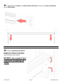
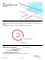
19 If the Silencer Vinyl was not already inserted, slide the SCV190 Silencer Vinyl into the Track.
Trim to length. This is the Track.
17 Using the provided Allen Wrench, tighten both Header
Set Screws.
18 Measure the Threshold Width [TW]: __________
SUBTRACT 5/8”
Cut the Curb Length [CL] to:___________

QCI5301 Rev 1 Page 19 Cered 6/5/2017
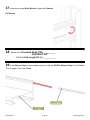
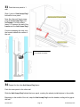
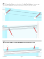
20Apply a 3/16” bead of silicone in the two grooves of the bottom side of the Track for the entire
length of the track.
21 Carefully put the Track into place on the threshold.

QCI5301 Rev 1 Page 20 Cered 6/5/2017
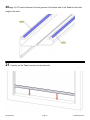
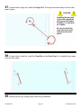
23 Install the rollers on the outer panel. The rollers will be on the inside of the shower.
-The rollers are mounted to adjustable cams. Install them with the rollers at the lowest position.
-Temporarily install the anti-jumps parallel to the floor.
-Only snug the screws for now.
NOTE: There are small part numbers on each part of the roller. All of them will face the glass.
22 Un-tape the Hold Downs and slide them to clamp down
on the Track tightly. Then insert and tighten the SCR30 Screw
into the Hold Down.
The Screw will push against the Wall Jamb and keep the Hold
Down in place.
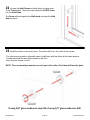
If using 3/8” glass connue to step 24A, if using 1/4” glass connue to 24B
Page is loading ...
Page is loading ...
Page is loading ...
Page is loading ...
Page is loading ...
Page is loading ...
Page is loading ...
Page is loading ...
Page is loading ...
-
 1
1
-
 2
2
-
 3
3
-
 4
4
-
 5
5
-
 6
6
-
 7
7
-
 8
8
-
 9
9
-
 10
10
-
 11
11
-
 12
12
-
 13
13
-
 14
14
-
 15
15
-
 16
16
-
 17
17
-
 18
18
-
 19
19
-
 20
20
-
 21
21
-
 22
22
-
 23
23
-
 24
24
-
 25
25
-
 26
26
-
 27
27
-
 28
28
-
 29
29


Unbranded RTLA05A5976XPSV Installation guide
- Type
- Installation guide
Ask a question and I''ll find the answer in the document
Finding information in a document is now easier with AI
Related papers
Other documents
-
 HiB Angled Grab Rail Fitting Instructions
-
 MODONA 4025-PC Installation guide
-
Custom Door & Mirror SB2-7280C Installation guide
-
Basco A0583-48CLBN Installation guide
-
 MODONA 6224D-A-B Installation guide
-
 MODONA 4024D-PC Installation guide
-
 MODONA 4024-RB Installation guide
-
 MODONA 9724D-CP Installation guide


