Page is loading ...

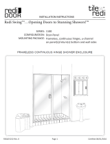
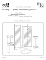
Model 750
Illustrated Installation
Instructions
Contractors Wardrobe
®
DESIGNERS • MANUFACTURERS
26121 Avenue Hall • Valencia, CA 91355 • (661) 257-1177 • Fax: (661) 257-4907
Toll Free: (800) CW-DOORS • (800) 293-6677 • www.CwDoor.com

#750 - I0750 - 0514
2
No. Qty Part # Part DescriPtioN
#1 1 A7600 Header - #750
#2 1 A7620 Curb - #750
#3 2 A7461 Wall Jamb
#4 1 G1170 Guide - #750
#5 1 Outside Door Panel
#6 1 Inside Door Panel
#7 4 A7630 Side Rail - #750
#8 2 A7650 Bottom Rail - #750
#9 2 A7640 Top Rail - #750
#10 4 W8120 Roller - #750
#11 2 J3000 Wall Jamb Bumper
#12 1 A6070 Towel Bar - #750
#13 2 BA75 Towel Bar Bracket
#14 2 H0750 Handle #750
#15 6 S81015 #6 x 1/4" "B"-Point Screw
#16 2 S83025 #8 x 1/2" PH B PT Screw
#17 4 S82010 Zinc #8-32 x 3/8" HWH Screw
#18 2 G2120GY Gray 1/8" - 5/32″ Door Vinyl
G2120G Gold 1/8" - 5/32″ Door Vinyl
15
22
22
22
19
3
23
16
15
13
20
19
23
11
7
9
17
10
5
18
7
7
17
23
13
12
23
16
15
23
8
4
8
2
6
18
10
17
9
1
15
23
19
3
22
14
15
7
20
23
11
22
19
22
Illustrated Parts Breakdown (IPB)
Drawing Model #750
(For shower head nozzle on right)
A - Note: The Handle (#14) is installed in this
location but is not displayed in the drawing.
See Step 13 for installation instructions of the
handle.
No. Qty Part # Part DescriPtioN
#19 4 S82070 Gold #8 x 1-1/2" FH SMS Screw
S82075 Silver
#20 2 S82060 Gold #8 x 1-1/2" PH SMS Screw
S82065 Silver
S82065W White
#21 1 S81025 #6 x 3/8" PH SMS Screw
#22 6 S0170 Screw Anchor
#23 8 S81060 #6 x 1-1/2" PH SMS Screw
S81065
S81065W
#24 1 L2050 Panel Locator
24
23
21
A

In this instruction booklet we will walk you through the
installation of your new shower door.
DO NOT REMOVE your old shower door until you
check that your new shower door kit is the right size
for your shower and that all the proper parts are in
the box or hardware bag. NOTE: The Header (#1) and
Curb (#2) are shipped 1” oversize, so you will need to
cut each to fit.
Use a level to check that the tub (sill/shower dam) is
reasonably level — not more than 1/4” out of level from
side to side. If it is out of level more than that, you may
want to consider ordering a custom-mitered fill that fits
under the Curb (#2). This will level the Curb (#2) correctly.
In the absence of leveling the Curb (#2) with a mitered fill,
and depending upon how badly your tub is out of level,
the panels may not stay in a closed position. Instead, the
panels may roll downhill, causing one of the doors to open.
Tools you will need:
• Phillips Head Screwdriver
• Level
• Electric Drill
• 1/8” Drill Bit (for fiberglass stall)
• 3/16” Masonry Drill Bit (for tile stall)
• Pencil
• Hammer
• Fine File
• Miter Box and Hacksaw with 32 teeth/inch Blade
• Caulking Gun and one Tube of Clear Tub/Tile Silicone
• 1/4” Open End Wrench
• Wire Cutters
• Tape Measure
• Duct Tape or some other type of reasonably heavy
Tape. Not Scotch Tape.
• Safety Glasses and Gloves
CAUTION: Wear safety glasses whenever drilling or
cutting. Handle the framed glass panels carefully. The
sharp corners of the panels can damage tile and floor
covering. Tempered glass cannot be cut. Do NOT let
the corners of the Door Panels strike the other glass
Door Panel or any hard surface, wall or floor. Even
tempered glass may be shattered in this manner.
STEP 1 Checking Contents of
Shower Door Package
DO NOT use a razor blade to cut open the paper wrapping
as you may scratch the contents. In the box or small hard-
ware parts bag you should find the following:
No. Qty. Description
(#1) 1 Header - #750 (approx. 1” oversized)
(#2) 1 Curb (approx. 1” oversized)
(#3) 2 Wall Jambs - #750
(#4) 1 Guide - #750
(#5) 1 Outside Door Panel
(#6) 1 Inside Door Panel
(#10) 4 Roller - #750
(#11) 2 Wall Jamb Bumper - #750
(#12) 1 Towel Bar - #750
(#13) 2 Towel Bar Bracket
(#14) 2 Handle - #750
(#15) 6 #6 x 1/4" "B"-Point Screw
(#16) 2 #8 x 1/2" PH B PT Screw
(#17) 4 #8-32 x 3/8” HWH Screw
(#19) 4 #8 x 1-1/2” FH SMS Screw
(#20) 2 #8 x 1-1/2” PH SMS Screw
(#21) 1 #6 x 3/8" PH SMS Screw
(#22) 6 Screw Anchor
If you find that any parts are damaged or missing,
refer to the parts list and IPB Drawing and contact
Contractors Wardrobe
®
’s Customer Service Department
at 661-257-1177. NOTE: Views and directions given in
these instructions — left, right, front, back, etc. — are
from outside the enclosure, facing the shower.
STEP 2 Removing Existing Shower Doors
After determining that your newly purchased shower
enclosure kit is the correct size, remove the existing
shower door and all existing parts of that door assembly.
Remove all screw anchors from the wall. Clean silicone
sealant or shower caulking and any other contami-
nants from shower and wall surfaces.
STEP 3 Installing Curb
NOTE: If your shower enclosure has a curve in the
corners at the side walls, be sure to measure the
distance from wall to wall above the curves.
3
#750 - I0750 - 0514

#750 - I0750 - 0514
A. Using the Tape Measure, measure between right
and left walls along the flattest part of the shower
sill.
B. Locate the Curb (#2). Cut the Curb (#2) 1-1/16"
shorter than this measurement. If your shower has
curved corners, use a File to round off and shape
the ends of the Curb (#2) to fit the rounded corners
(See Figure 1). Do not cut the Header (#1) at
this time.
C. Lay the Curb (#2) on the shower sill with the
sloping face of the Track towards the inside of the
shower. Center the Curb (#2) on the shower sill,
and secure it in position with strips of Duct Tape.
Mark the position on the sill with a Pencil (See
Figure 2).
NOTE: The Curb (#2) must lie flat. If the enclosure has
curved corners you may have to shape the Curb
(#2) with the File so that it will lie flat on the sill.
STEP 4 Drilling and Aligning
the Wall Jambs
A. Locate the Wall Jambs (#3). Looking at a Wall
Jamb (#3) you will notice that the Wall Jamb (#3)
has two side legs, one which is narrower than the
other. This narrow leg will face into the shower.
B. Drill three 3/16" diameter holes in the center of
the Wall Jamb (#3) as illustrated in Figure 3. Drill
a hole 3" from each end and one in the center.
If you are replacing an existing unit and there
are already holes in the fiberglass or tile/marble,
drill the holes in the Wall Jamb (#3) at the same
location where the existing holes are. Place the
Wall Jamb (#3) next to the existing holes, using
a Pencil, mark the Wall Jamb (#3) with the same
location as the existing holes.
C. Holding the Wall
Jamb (#3) with the
narrow leg towards
the inside of the
shower, lower the
Wall Jamb (#3) onto
the Curb (#2). The
Wall Jamb (#3) must
lie flat against the
wall and both legs of
the Wall Jamb (#3)
must fully connect
with the Curb (#2).
NOTE: If your shower has curved corners, you may have
to shape the Wall Jambs (#3) to fit snugly with the
Curb (#2).
D. With the Wall Jamb (#3) in place, use a Level
to ensure that the Wall Jamb (#3) aligns straight
up and down. Use your Pencil to mark the hole
locations.
E. Using either a 1/8" Drill Bit
(for a fiberglass enclosure)
or a 3/16" Masonry Drill
Bit (for tile/marble), drill
holes where you made the
marks. If installing in a tile/
marble enclosure, gently
tap a Screw Anchor (#22)
into each hole. DO NOT
use the Screw Anchors
(#22) for a fiberglass
enclosure.
F.
Repeat this for the other Wall
Jamb (#3). Remove the two
Wall Jambs (#3) for now.
4
Figure 1
Round off
both ends of the
Curb (#2) and Wall
Jambs if necessary.
A
Center Curb (#2) on sill and mark
position with Pencil
Figure 2
Centerline
Pencil
Mark
Wall
Jamb
Inside of
shower
Level
3/16" diameter holes
Figure 3
3"
Drill center hole
3"
Shorter
leg of Wall
Jamb faces
into inside
of shower
Curb
(#2)

STEP 7 Installing the Panel Locator
A. In order to install the Panel Locator (#24) you
must first determine which wall the shower head is
on. See Figures 5A and 5B. If the shower head is
on the right wall, refer to Figure 5A to position the
Panel Locator (#24). If the shower head is on the
left, refer to Figure 5B. Attach the Panel Locator
(#24) to the edge of the Wall Jamb (#3) facing the
inside of the shower, on the shower head side, as
shown.
G. Remove the Curb (#2). Gently center punch
the three holes along each Wall Jamb (#3). On
ceramic tile be very careful and only tap the punch
lightly enough to nick the tile surface but not crack
the tile.
H. Use the 3/16" Drill Bit and drill holes into the
wall for both Wall Jambs (#3). When finished,
be sure to clean the shower sill of any debris
from drilling.
I. Insert a Screw Anchor (#22) into each of the six
holes.
STEP 5 Caulking and Installing
the Curb
A. Apply Silicone along the underside of the Curb
(#2) as shown in Figure 4. Only apply enough
Silicone to just barely overfill the grooves.
B. Using the location marks install the Curb (#2) and
seal both ends at the wall with Silicone.
STEP 6 Installing Wall Jambs
and Bumpers
A. With the narrow leg of
each Wall Jamb (#3)
toward the inside of the
shower enclosure, install
the Wall Jambs (#3) by
setting each one down
over the Curb (#2) and
re-aligning the holes of
each Wall Jamb (#3)
with the holes you drilled
in each wall.
B. Use two #8 x 1-1/2" FH SMS Screws (#19), top
and bottom, to secure each Wall Jamb (#3) to the
wall.
C. Use two #8 x 1-1/2" PH SMS Screws (#20) to
secure Wall Jamb Bumpers (#11) in the center
hole of each Wall Jamb (#3).
D. Tighten all screws.
Figure 4
Caulk
Curb (#2)
Turn Curb (#2) over before
installing on the sill
#750 - I0750 - 0514
Shorter
leg of Wall
Jamb faces
into inside
of shower
Curb
(#2)
Shower head
and controls
left side
24
3
3
11
20
Figure 5B
11
20
5
Figure 5A
3
11
20
20
11
3
24
Shower head
and controls
right side

STEP 8 Measuring and Installing
the Header
A. Locate the Header (#1) and two #6 x 1/4" "B"-Point
Screws (#15).
B. Measure the distance, wall to wall, at the top of the
Wall Jambs (#3). Cut the Header (#1) 1/16" shorter
than this measurement to allow for clearance.
C. Install the Header (#1) over the ends of the Wall
Jambs (#3). Stand in the shower for the next
steps.
D. On both ends of the Header (#1), measure 5/16"
in from the end and 5/16" up from the bottom edge
and mark these two points with a Pencil. Using
a 7/64" Drill Bit, at each pencil mark, carefully
drill all the way through the Header (#1) and into
the Wall Jamb (#3).
E. Finish installation of the Header (#1) by securing
it to the Wall Jambs (#3) with the two
#6 x 1/4" "B"-Point Screws (#15).
STEP 9 Installing the Rollers
on the Panels
Please note: Enclosures with Obscure or Smooth Rough
glass are installed with the textured surface of the framed
Panels facing out, or to the front. The smooth surface of
the glass will face into the shower. This orientation gives
you the front and back of each panel. Now, select one of
these panels to be the Outside Door Panel (#5) and one to
be the Inside Door Panel (#6).
A. Use two #8-32 x 3/8" HWH
Screws (#17) and attach two
Rollers (#10) to the top of the
Outside Door Panel (#5) on the
front surface of the “fin”, with
the metal parts (the Nut side)
against the frame and the plastic
Roller (#10) facing out of the
shower (the same side as the
textured side of the glass).
#750 - I0750 - 0514
B. Use two more #8-32 x 3/8" HWH Screws (#17) to
attach two Rollers (#10) to the top of the Inside
Door Panel (#6) of the frame on the back surface
of the “fin”, with the metal parts (the Nut side)
against the frame and the plastic Roller (#10)
facing into the shower (the same side as the
smooth side of the glass).
STEP 10 Installing the Door Panels
Installing the door panels may be easier if you have
someone assisting you. Always wear gloves and safety
goggles whenever handling glass. NOTE: DO NOT allow
the panels to strike the shower/tile or each other.
A. Hold the Inside Door Panel
(#6) so that the Rollers (#10)
are facing away from you.
Standing outside of and
facing the shower enclosure,
lift the Inside Door Panel
(#6) up and over the Curb
(#2) and then lift the Top
Rail (#9) up into the Header
(#1) and set the Rollers
(#10) into the rear track of
the Header (#1).
B. Gently lower the Rollers
(#10) into position so that they are seated in the
track. Make sure that the Panel rolls freely.
C. Hold the Outside Door Panel
(#5) so that the Rollers (#10)
are facing towards you.
Standing outside of and
facing the shower enclosure,
use the index finger of both
hands to carefully push the
Inside Door Panel (#6) back
and out of the way as you lift
the Outside Door Panel (#5)
up and over the Curb (#2)
and then slide the Top Rail
(#9) up and into the Header
(#1). Or, if someone is
assisting you, have him/her
hold the Inside Door Panel
(#6) back out of your way.
DO NOT let the two Panels (#5 and #6) strike one
another. Set the Rollers (#10) into the front track of
the Header (#1).
D. VERY CAREFULLY seat the Outside Door Panel
(#5) into the track and make sure that it rolls
freely. Carefully let the Inside Door Panel (#6)
ease back into position.
E. Slide both Panels (#5 and #6) to one side.
6
Outside Panel
(Textured side)
Inside Panel (Smooth side)
Frame
Top
Outside
Panel
(Textured
side)
Nut
Outside
Shower
Inside
Shower
A
B
A
Outside
Shower
D
Push
Inside
Panel
away
with your
fingers
C

#750 - I0750 - 0514
7
STEP 11 Installing the Guide
A. Locate the Guide (#4) and one #6 x 3/8" PH SMS
Screw (#21). Standing inside the shower, position
the Guide (#4) on the Curb (#2) exactly midway
between the Wall Jambs (#3). The Guide (#4) will
lay flush on the Curb (#2).
B. Using the hole in the
Guide (#4), drill a 1/8"
hole into the Curb (#2).
C. Use a
#6 x 3/8" PH SMS
Screw (#21) to secure
the Guide (#4) in place.
STEP 12 Installing the Towel Bar
A. Locate the Towel Bar (#12), two Towel Bar
Brackets (#13), two #6 x 1/4" "B"-Point Screws
(#15), and two #8 x 1/2" PH B PT Screws (#16).
Refer to the IPB Drawing to help identify these
parts.
B. Align the pre-drilled hole in the Towel Bar Bracket
(#13) with the pre-drilled hole in the door Side
Rail (#7) of the Outside Door Panel (#5). Use a
#6 x 1/4" "B"-Point Screw (#15) to loosely attach
the Towel Bar Bracket (#13) to the door Side Rail
(#7) of the Outside Door Panel (#5). Repeat these
same steps for the other side.
C. Align the pre-drilled hole in the Towel Bar (#12)
with the pre-drilled hole in the Towel Bar Bracket
(#13). On the Outside Door Panel (#5) use a
#8 x 1/2" PH B PT Screw (#16) to secure the
Towel Bar (#12) to the Towel Bar Bracket (#13).
Repeat these same steps for the other side.
D. Tighten the two #6 x 1/4" "B"-Point Screws (#15)
to the Side Rail (#7) of the Outside Door Panel
(#5).
STEP 13 Installing the Handles
A. Locate two Handles (#14) and two #6 x 1/4"
"B"-Point Screws (#15).
B. Standing in the shower, with the curved part of
the handle facing into the shower, position the
Handle (#14) midway on the frame of the Inside
Door Panel (#6) (as measured from the bottom
of the Panel), on the edge nearest the Wall Jamb
(#3) near the shower head. Use a #6 x 1/4"
"B"-Point Screw (#15) to attach the Handle (#14)
to the Side Rail (#7) of the Inside Door Panel
(#6).
C. Repeat these steps for the other side of the Inside
Door Panel (#6).
STEP 14 Silicone Sealing the Enclosure
A. Using Clear Silicone seal along the interior and
exterior edges of the Header (#1), Wall Jambs
(#3) and Curb (#2).
NOTE: Silicone sealant must cure for 24 hours before
you use your new enclosure. Silicones may vary.
Please follow curing instructions on the tube of
Silicone.
Inside
of shower
Position Handle
midway on Door Panel
Handle:
Curved part
faces into
shower
Handle (#14)
Install the
Guide midway between
the Wall Jambs
Caulk where:
• Wall Jambs and wall meet
• Curb (#2) and Wall Jambs
meet
• Curb (#2) and shower sill
meet

8
#750 - I0750 - 0514
Thank you for purchasing a Cw
®
Shower Enclosure. If
you like this product, we invite you to visit our website
at www.CwDoor.com for more information about our
extensive line of other shower Enclosures, Room
Partitions and Loft Dividers, Cabinet Doors, and
Wardrobe Doors. They feature Duratuf
®
Tempered
Safety Glass, Painted Glass, CwShield™ Protective
Coating and Duraflect
®
Copper-Free Mirror.
STEP 15 Cleaning and Removing the
Door Panels
The enclosure Door Panels (#5 and #6) are not
designed to be removed once they are installed.
However, inconvenient areas that you may want to
clean, such as the overlap between the doors, can still
be reached for cleaning.
A. Carefully remove all the hardware from door.
This will enable you to slide the glass Door
Panels (#5 and #6) in either direction to clean
them thoroughly.
B. Clean the glass and Curb (#2) with a mild, non-
abrasive cleaner.
C. Re-install the hardware when you are finished.
CAUTION: Removing one or both of the Door Panels
(#5 and #6) should NOT be attempted without
assistance. Always wear safety goggles and
gloves when handling the glass Door Panels (#5
and #6). Read through the following instructions
first to familiarize yourself before proceeding.
D. Carefully remove any Silicone from around the
Header (#1).
E. Remove the #6 x 1/4" “B”-Point Screw (#15)
from the Header (#1). Slide both Door Panels
(#5 and #6) to one side and have someone
assist you by supporting the Door Panels (#5
and #6).
F. You should now be able to raise the Header
(#1) enough to lift the Door Panels (#5 and #6)
out of the Guide (#4) and disengage them from
the Header (#1).
G. To re-install the Door Panels (#5 and #6),
reverse the process described above: hang the
Door Panels (#5 and #6) in the Header (#1) and
re-attach the Header (#1) onto the Wall Jambs
(#3) with two #6 x 1/4" “B”-Point Screws (#15).
Re-install the hardware.
/