Page is loading ...

READ AND SAVE THESE INSTRUCTIONS
VAPOR-LOGIC
MICROPROCESSOR-BASED HUMIDIFIER
CONTROL SYSTEM
Installation Instructions
and
Maintenance Operations
Manual
®

2
TABLE OF CONTENTS
TO THE PURCHASER AND THE INSTALLER
Thank you for purchasing the VAPOR-LOGIC
®
microprocessor-based humidifier control system. We have
designed and developed this system to give you total satisfaction and many years of trouble-free service. Proper
installation and operating practices will assure you of achieving that objective. We urge you to become familiar
with the contents of this manual.
DRI-STEEM Humidifier Company
VAPOR-LOGIC Program Code Nomenclature...................................... 3
VAPOR-LOGIC
®
Microprocessor Installation Checklist...................... 4
Placement and Wiring of Sensing Devices
Sensing Device Placement ................................................................ 5
Control Precautions............................................................................ 5
Humidistats and Transmitters ............................................................ 6
Earth Bar Wiring................................................................................. 7
Placement and Wiring of Optional Sensing Devices........................... 8
Proper Wiring Procedures ..................................................................... 9
VAPOR-LOGIC Control Cabinet Installation ........................................ 10
VAPOR-LOGIC Key Pad / Digital Display Installation ......................... 11
Start-up Instructions .............................................................................. 12
Start-up Trouble-Shooting Checklist.................................................... 13
Introduction to VAPOR-LOGIC.............................................................. 14
VAPOR-LOGIC Control Board Connections ........................................ 15
VAPOR-LOGIC Control Board Operation ............................................. 17
VAPOR-LOGIC Function Keys Self-Test Procedure............................ 19
VAPOR-LOGIC Key Pad / Digital Display Operation ........................... 21
Key Pad Description ................................................................................. 21
Accessing VAPOR-LOGIC Sub-Menu Information................................... 22
Sub-Menu Instructions for V2.04 Firmware .............................................. 23
Activating Digital Meter for V2.04 Firmware ............................................. 24
VAPOR-LOGIC Control Schemes.......................................................... 25
VAPOR-LOGIC P.I.D. Control Loop: Terminology.............................. 28
VAPOR-LOGIC P.I.D. Control Loop: Tuning ....................................... 30
Main Menu / Auto Scroll Information .................................................... 33
Digital Display Read Outs ...................................................................... 35
Digital Display / Key Pad Trouble Shooting Guide.............................. 36
Fault Indicator Codes ............................................................................. 38
Trouble-Shooting Guide ........................................................................ 42
Replacement Parts ................................................................................. 49
Glossary .................................................................................................. 50
Two-Year Limited Warranty ................................................................... 52

3
OM-361
VAPOR-LOGIC
®
PROGRAM CODE NOMENCLATURE
An eleven digit VAPOR-LOGIC program code appears on the front of the control cabinet and on the wiring diagram
inside of the control cabinet. The program code specifies the parameters necessary for the
VAPOR-LOGIC microprocessor to control your system. An explanation of the program code is detailed below.

4
IMPORTANT: Before installing your VAPOR-LOGIC
control system, review this checklist to ensure proper
installation of the product. Failure to follow the recom-
mendations listed below could result in failure or
damage to the humidifier or microprocessor.
1. Read this manual and information before
starting.
2. Wiring diagram and information are located
inside the control cabinet door. All information
should remain with the control cabinet after
installation.
3. Locate the control cabinet so that the wire
length from the control cabinet to the
humidifier is 15 metres or less.
4. Connect an approved electric earth ground to
the protective earthing bar in the control
cabinet.
5. Never route the low voltage field control wires
near the line voltage section of the control
cabinet or in the same conduit or cable tray as
line voltage wires.
6. Never use shielded cable for water level probe
wiring.
7. For proper humidifier operation, the heater/
machine ground lug in the junction box must be
attached to the protective earthing bar with the
same size wire as is used in the heater wiring.
8. All humidity and temperature sensor wiring shall
be a 2 or 3-wire, 1.0 mm
2
shield plenum non-
conduit-rated cable with drain wire (see
wiring diagram for appropriate connections).
9. A "shield" grounding connection is provided on
the control cabinet sub-panel to ground the cable
shielding. Do not ground shield at sensor end.
10. Digital Display Module/(key pad) Installation
Precautions
a. Do not locate key pad inside control cabinet.
b. Route modular cable within control cabinet
separated from line voltage circuits.
c. Do not connect or disconnect the modular
cable while power is applied to the
VAPOR-LOGIC board.
11. Verify that VAPOR-LOGIC program code
which is detailed on page 3 of this manual
matches field requirements.
12. Follow the recommended control cabinet field
conduit knockout locations. (See diagram 4-1.)
Knockouts
For Control
Wiring
Diagram identifies recommended knockout locations for
power and control field wiring. (See notes 5 & 6.)
Figure 4-1: Control Cabinet
OM-762
Knockouts
For Heater Wiring
Knockouts For
Power Wiring
VAPOR-LOGIC
®
INSTALLATION CHECKLIST
CAUTION - When providing
holes and knockouts in the
control cabinet, protect all
internal components from debris
and vacuum out cabinet when
finished. Failure to comply with
this warning may damage
sensitive electronic components
and void the DRI-STEEM
warranty.

5
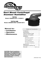
Figure 5-1: Recommended Placement of Humidistat Control or Humidity and Temperature Transmitters
Temperature compensation transmitter
located on lower corner of the inside
surface of double pane window glass
B
A
North or North-
East Facing
Window
B
A
B
C
Air Handling Unit
Humidifier
AHU
B
Return Air
Relief Air
D
Outside Air
Point of Vapor Absorption
Vapor Absorption Has Taken
Place
Air Flow Switch (sail type recom-
mended for VAV application)
High Limit Humidistat or High Limit Transmitter (set at
90% RH max.) Placement for VAV Applications
(3
metres)
Line
Voltage
24 Volt
Liquid Level Detectors
Electrical Supply
Key Pad
UL-listed IP 52
VAPORSTREAM
®
VLC Humidifier
Duct
ULTRA-
SORB
®
Recommended Sensor
Locations
A) Best
B) Alternative Location
C) Not Recommended
D) Best Duct High Limit Humidistat
PLACEMENT OF SENSING DEVICES
Sensing Device Placement
The location of the humidity sensing devices is very
important to achieve accurate humidity control. A
drawing of a typical small air handling system is shown
below (figure 5-1). For the best control, place the
humidity sensing device in the center of room, or just
inside of the return air duct (location “A”). This will
provide the least amount of variation caused by air flow
patterns and room temperature. Placement of the duct
humidity sensing device within outlet of air handler
(location “D”) is ideal for duct high limit control, but the
actual placement must be downstream from dispersion
tubes a sufficient distance to ensure steam absorption
has taken place. Accurate control of temperatures in
room and ducts is also very important to improve
control of relative humidity.
Control Precautions
Unsatisfactory results from humidifying control may
involve more than just the controller’s capability to
control the system. Other factors that play an important
role in overall system control are:
• Size of the humidification system relative to
load.
• Overall system dynamics associated with
moisture migration time lags.
• Accuracy of humidistats and humidity transmit-
ters and their location.
• Dry bulb temperature accuracy in space or
duct.
• Velocities and air flow patterns in ducts and
space environments.
• Electrical noise or interference.
OM-828
24
Volt
Liquid Level
Detectors

6
Wiring On-Off Humidistats
DRI-STEEM may provide three types of on-off
controls: wall mounted, duct mounted or pneumatic/
electric relay. The wiring diagram (found on the inside
of the humidifier control cabinet) will show proper
wiring for these controls.
Wiring Modulating Humidistats
The standard modulating humidistat controllers
DRI-STEEM provides either duct or wall mounted
humidistats.
The humidistats are powered by 21 VDC supply
provided by the VAPOR-LOGIC
®
control board. A
6-9 VDC control signal is returned to provide the
modulating function.
Using a pneumatic modulating signal, DRI-STEEM may
provide a transducer to accept a 20-140 kPa pneumatic
input range.
A two-wire 0-135 ohm humidistat is also adaptable to
the VAPOR-LOGIC control board.
Wiring Modulating Humidity or Temperature
Transmitters
All transmitters provided by DRI-STEEM are two-wire
devices. (See your wiring diagram for proper
connections.) The humidity transmitters have a range
of 0-100% RH with an output of 4-20 mA. The
temperature transmitter has a range of -29° to 71° C
and produces a 4-20 mA signal.
Figure 6-1: Example of Proper Shielding Techniques When Connecting Humidity or Temperature Devices
to VAPOR-LOGIC Control Inputs
OM-295
OM-811
*OPTIONAL
Note: The wiring diagram (found
on the inside of the humidifier
control cabinet) will show the proper
controls wiring.
CONTROL
PANEL
SHIELD GND
* FREEZE PROTECTION
AQUASTAT
AIR FLOW SWITCH
4-20 MA
0-100% RH
* TEMPERATURE
COMPENSATION
TRANSMITTER
(T184) 4-20
MA -29° TO
49° C
* HIGH LIMIT
HUMIDITY
TRANSMITTER
4-20 MA
0-100% RH
CONTROL
HUMIDITY
TRANSMITTER
1.0 mm
SHIELDED CABLE
TERMINAL
BLOCK J8
HIGH LIMIT
HUMIDISTAT
0-135 OHM, 6-9 VDC,
OR
4-20 MA CONTROLLER
(SUPPLIED BY
OTHERS)
VL MASTER BOARD
TERMINAL BLOCK J8
CONTROL
PANEL
SHIELD GND
FREEZE
PROTECTION
AQUASTAT
(OPTIONAL)
1.0 mm
2
SHIELD
CABLE
BREAK
ON
RISE
WIRING OF SENSING DEVICES
Important: Consult control cabinet wiring diagram. Control changes require wiring and
programming changes.
(T184-H) 4-20
MA -29° TO
71° C
AIR FLOW
SWITCH

7
Sensor Wires
To Control
Board
Shield Ground
Drain Wire (less than 50 mm)
To
Sensor
OM-1008
WIRING OF SENSING DEVICES
Figure 7-1: Earth Bar Wiring
• Control wiring and power wiring must be run in
dedicated or separate earthed metal conduit, cable
trays, or trunking.
• Grounding requirements - The earth must be made
by solid metal to metal connections. The ground must
be good radio frequency earth. Ground wire should be
the same size as power wiring.
For maximum E.M.C. effectiveness, all humidity,
temperature and air flow controls should be wired
using multi-conductor shielded plenum-rated cable
with a drain wire for the shield. The drain wire should
be connected to the shield ground terminal with it's
length kept to less than 50 mm.
• When selecting a space to install the humidifier,
avoid areas close to sources of electromagnetic
emissions such as KVA transformers and variable
frequency drives.

8
Double
Pane
Window
Glass
Secure temperature
sensor tip, to inside
surface of window glass
using clear RTV silicone
adhesive
Typical Sensor
Cord Routing
OM-337
Window Framing
OPTION: Variable Air Volume (VAV) (Shielded cable
recommended, see note.)
When the VAV control option is requested,
DRI-STEEM will provide, in addition to the room control
transmitter, a duct mounted humidity transmitter (4-20
mA output over 0-100% RH range).
The modulating high limit transmitter signal operates in
conjunction with the Room or Duct controlling
transmitter signal through the VAPOR-LOGIC
®
control
system to prevent over humidification in the duct work.
VAPOR-LOGIC will start lowering the humidifier output
when the duct relative humidity is within 6 percent of
the duct high limit set point.
When this occurs, the digital key pad will display the
message "VAV OUTPUT LIMIT". If necessary, the
reduction of the humidifier output will continue until
maximum high limit set point has been reached,
shutting off the humidifier completely.
When the high relative humidity starts to decrease in
the duct, VAPOR-LOGIC will slowly start to increase
the production of steam vapor. When the duct relative
humidity decreases to a point greater than 6 percent
below the duct high limit set point, the control
transmitter will be restored as the primary controller
and the key pad will remove the "VAV OUTPUT LIMIT"
text, returning the control system to normal operation.
PLACEMENT AND WIRING OF OPTIONAL SENSING DEVICES
The key pad will display the amount of offset that has
take
n place, "OFFSET RH=___%". As the interior
window glass temperature increases,
VAPOR-LOGIC will reduce the offset and restore
system control to the n
ormal RH set point for the
space.
The transmitter provided with VAPOR-LOGIC is cali-
brated for -29° C to 71° C with output from 4-20 mA. A
temperature reading of 21
°
C should produce a mea-
surement of 12 mA.
Note: DRI-STEEM recommends using 1.0 mm
2
plenum rated shielded cable for transmitter wiring
and grounding shield at a common point in the
control cabinet (see figure 8-1).
Cold Snap Transmitter Placement (See figure 8-2.)
1. Position the cold snap transmitter control
box on a wall adjacent to window frame.
2. Place flat surface of temperature sensor tip
on lower corner of glass surface.
3. Temporarily hold the sensor tip in place with
strips of masking tape.
4. Apply a small amount of clear RTV silicone
adhesive over and around the sensor tip
(making sure the sensor tip is in contact with
the window glass).
5. After adhesive has cured, remove masking
tape.
Figure 8-1: Shielded Cable
Shielded Cable
VAPOR-LOGIC
®
Sensor
Tip
11
12
Shield
Ground
Temperature
Transmitter
OM-
311
Ground shield at control panel end only. Do
not ground shield at device end.
OPTION: Cold Snap RH Offset (Shielded cable
recommended, see note). When selected as an option,
DRI-STEEM provides a cold snap temperature
transmitter.
The cold snap temperature transmitter continually
monitors the interior window glass temperature and
transmits this temperature to VAPOR-LOGIC.
VAPOR-LOGIC then compares the glass temperature
to the desired RH set point in the humidified area and
calculates the dew point (
°C) for the space. VAPOR-
LOGIC will lower (offset) the desired RH set point to a
safe condition, where condensation will not form on
windows.
Thermostat Control
Wires
Surface Mounted
Thermostat
Temperature
Control
Box on Wall
Figure 8-2: Cold Snap Transmitter Placement

9
Electrical noise can produce undesirable effects on
the electronic control circuits that can affect controllabil-
ity. Electrical noise is generated by electrical equipment,
such as resistive loads, electric motors, solenoid coils,
welding machinery, fluorescent light circuits, etc. The
electrical noise or interference generated from these
sources (and the effects on controllers) is very difficult
to define, but most common symptoms are erratic
operation or intermittent problems.
However, most noise problems can be prevented by
using wiring practices and techniques which prevent
coupling or inducing of electrical interference into
control circuits. Some simple wiring practices associ-
ated with DRI-STEEM humidifier equipment should
minimize interaction of noise and controls:
• Humidifier and control cabinets must be
connected to a code approved earth ground.
• When routing electrical wiring inside the
control cabinet, separate the line voltage
wiring from low voltage control circuit wiring.
• Use separate electrical conduits or cable
trays for line and low voltage control wiring
from the humidifier to humidity sensors,
airflow switches, etc.
OM-
829
*Independent of Line Voltage Wiring
To Humidifier
Probe Head On
Tank
Figure 9-1: Probe Wiring
Brown (full) Probe Rod Level A
Orange (refill) Probe Rod Level B
Violet (low water) Probe Rod Level C
or DI Low Water Cut-Off Switch
Probe Wiring To
Be 1.0 mm
2
Stranded Wire
Run In Conduit*
Do Not Use
Shielded Cable
For Probe
Wiring.
4
3
2
1
PROPER WIRING PROCEDURES
• Do not use chassis or safety grounds as
current carrying commons. No safety
grounds should ever be used as a conductor
or neutral to return circuit current.
• The preferred method of external electrical
connections to humidistats, room/duct
humidity and temperature transmitters, and
control signal input connections from building
control systems is minimum 1.0 mm
2
plenum
rated wire cable of twisted pair type, includ-
ing cable shielding and drain wire for ground-
ing.
• All grounding of shielded cable connections
should be returned to the control cabinet
and tied to the protective earthing bar. Do
not ground shield at the device end.
• IMPORTANT: Locate the control cabinet
so that wire lengths are 15 metres or less
to the humidifier.
• Probe and low water cut off wiring must be
individual 1.0 mm
2
stranded wire run in
conduit (see figure 9-1). Do not use shielded
cable for probe wiring.

10
VAPOR-LOGIC
®
CONTROL CABINET INSTALLATION
The VAPOR-LOGIC control board is shipped mounted
with all internal wiring completed within a control
cabinet. All software has been custom programmed into
your VAPOR-LOGIC system according to the original
order requirements. Refer to the
VAPOR-LOGIC control board drawing for detail of the
board and connection points. (See figure 14-1 on page
14.)
The VAPOR-LOGIC control board should always be
wired following local electric codes. VAPOR-LOGIC is
powered by a low voltage control transformer. The
transformer provides a 24 VAC supply, and is protected
by an integral manual reset circuit breaker.
All humidifier power wiring is represented on the
humidifier wiring diagram.* Follow field wire torque
requirements shown on the humidifier wiring diagram
when connecting the power and control wiring inside
the humidifier control cabinet. Additional precautions
about VAPOR-LOGIC control board connections are:
• Use 3 mm straight blade screwdriver on
VAPOR-LOGIC control board terminal blocks.
• DRI-STEEM recommends a single 1.0 mm
2
pre-tinned wire in each terminal at the
VAPOR-LOGIC terminal block. Torque to 0.1 Nm.
• When terminating multiple wires to VAPOR-LOGIC
control board terminal blocks, DRI-STEEM
recommends securing the multiple wires and one
additional wire with appropriately sized wire nut. Use
the single additional wire's opposite end to connect to
the VAPOR-LOGIC terminal block.
• Never run control system wires bundled with, or in
the same conduit as, power wires.
• Pick a location that will allow for easy access to the
control cabinet and internal electrical components.
Mount control cabinet using the mounting tabs.
IMPORTANT: Locate the control cabinet so that
wire lengths are 15 metres or less to the
humidifier.
*A wiring diagram and installation guide is attached to
the inside of control cabinet door. All instructions
should remain with the control cabinet after
installation.

11
Installing Modular Cable
Important: To properly identify the second remote key
pad to the master VAPOR-LOGIC microprocessor, a
shunt connection is provided and installed by
DRI-STEEM across a connector pin. Refer to the digital
module printed circuit board in figure 19-1 on page 19
to confirm location and placement.
Align the front section over the two top finger hooks on
the back section, rotate down, and snap front section
onto the back section. Route modular cable as needed
to control cabinet and drill necessary hole for appropri-
ate cable strain relief fitting. Note: Do not wrap cable
around the key pad. When routing modular cable
inside the control cabinet, route cable away from all
power wiring and connect the male modular plug into
either VAPOR-LOGIC printed circuit board-mounted
female modular receptacles, J1 or J2. Push male plug
in until you hear a “click.” (The cable may be plugged
into either J1 or J2 on the keypad as well.) The 4-wire
cable provides the DC power to the digital module and
completes the RS485 type digital communication
between the local and/or remote modules and the
VAPOR-LOGIC control board.
Caution: When fabricating longer modular cables,
electrical polarity is very important in securing the
type RJ11 male plugs to cable. Both ends of cable
polarity connections must be identical. (See figure
11-1.)
Installing the Key Pad
Do not leave the keypad inside the control cabinet.
The hardware is pre-mounted in a thermoplastic case
with front access to the digital display and key pad.
DRI-STEEM also provides 4-wire pre-connected
modular cables with male modular plugs attached. The
modular plugs are 6-position 4-wire type RJ11 arrange-
ment. Position case in a convenient location for easy
access. The ambient temperature range for modules
is 0° to 50° C. Exceeding these limits will result in a
poor reading, or no reading at all.
The digital display key pad case is fabricated in two
sections; light pressure at the base of the back of the
case will separate the two sections. The front half
includes the electronic display module control board
and key pad, which are secured by four screws.
DRI-STEEM recommends the back section of enclo-
sure be secured to a standard electrical switch box with
modular cable routed out the rear of the case. (See
figure 11-2.)
A second choice is a direct mount to any surface using
field supplied screws. Route modular cable out the
bottom of enclosure. Because of various mounting
possibilities, first provide the necessary clearance holes
for the hardware you are using by opening the two pilot
mounting holes on the back of enclosure. Mount the
back of enclosure to a flat surface and secure as
necessary. Caution: Overtightening will distort the
back of the case.
VAPOR-LOGIC
®
KEY PAD / DIGITAL DISPLAY INSTALLATION
Figure 11-1: Cable Polarity Connections
4 Electrical
Connection
Points
Yellow
Green
Red
Black
Identical
Electrical
Polarity
Yellow
Green
Red
Black
RJ11 Type
Male Modular
Plug
Modular 4
Wire Cable
Figure 11-2: Exploded View of Key Pad/Digital Display
OM-411
OM-332

12
pad will display “LOW WATER” as part of auto scroll
text.
11. Airflow switch input must be closed.
12. High limit humidistat input must be closed or
Variable Air Volume (VAV) control system high limit
transmitter must be connected.
13. If aquastat option is furnished, connections to
terminals #16 and #17 are necessary.
14. With sufficient water in tank, (on some newer
models a green LED lamp on the control board will be
illuminated), airflow switch closed, high limit humidistat
closed, and a call for humidity, the heater outputs will
be energized. If the tank does not contain water and
the heaters are energized by the VAPOR-LOGIC
control system, a serious failure will result. Immediately
remove power from the system and verify that all wiring
is done per the wiring instructions in this manual and
the unit wiring diagram.
15. During normal operation, the key pad will display
auto scroll features of humidifier operating status. See
pages 30 and 31 for descriptions.
16. To change any of the operating parameters,
depress the “MODE” key on key pad to activate the
VAPOR-LOGIC main menu. Use the up-down arrow
keys to select a main menu item. Press ENT key to
allow you to change the operating parameters. Refer to
pages 21 and 22 for a complete description and pages
30 and 31 for all the other possible main menu items.
17. If necessary to restart VAPOR-LOGIC, depress
the reset button on the electrical sub-panel, hold for a
few seconds, then release.
1. Confirm that the control signal being connected to
the VAPOR-LOGIC
®
system is compatible with the
VAPOR-LOGIC program. Identify the VAPOR-LOGIC
program code on the wiring diagram or on the outside
of control cabinet door. Refer to the VAPOR-LOGIC
Manual to decipher the code using the nomenclature
description on page 3.
2. Confirm all wiring is correct per wiring diagram.
3. Confirm that proper grounding and an approved
earth ground are provided.
4. Confirm J9, J10, J11 shunt connectors on
VAPOR-LOGIC board are in their correct position per
wiring diagram. See page 14 for the physical locations.
5. Confirm four position slide switch on
VAPOR-LOGIC board is in “AUTO” position.
6. Confirm that the digital key pad is mounted on the
outside of the control cabinet with modular cable routed
away from the high voltage circuits and connected to
either J1 or J2 female connector on control board.
7. Turn water supply on, confirm drain valve is closed.
8. Turn power on, the key pad will display the
introduction of “VAPOR-LOGIC”, transfer into
INITIALIZING, and the enter into AUTO mode. In
AUTO mode, the system will continuously scroll system
operations status (see pages 33 and 34).
9. In normal operation, the red LED lamp on
VAPOR-LOGIC board will blink off-on like a heart beat.
(In fault mode, the red LED lamp will blink a pulse
code.)
10. System will initiate filling of the tank with water, key
START-UP INSTRUCTIONS

13
If you are experiencing a problem with starting up your
system, please refer to the following:
1. Verify that wiring is done per instructions in
this manual and the unit wiring diagram.
2. Make sure key pad is not inside of the control
cabinet.
3. Check water level control voltages; the
reading should be 2.5 VAC without water, 0
VAC with water from ground (pin 4-J12) to
probe inputs (pins 1, 2 & 3-J12).
4. Check the throttling range on the Main Menu
of the keypad (default is 11%).
5. Check cycle setting on the Main Menu of the
keypad (default is 60 seconds; default is 4
seconds with SCR).
6. Check delay setting on the Main Menu of the
keypad (default is 20 seconds).
7. Check time to auto drain (default is 50 hours).
8. Check drain duration (default is 8 minutes).
9. Check drain and flush sequence (default is 8
minutes).
10. Check RH setting.
11. Check control signal.
12. Perform test cycle of the system.
13. Check amp draw of heater(s); refer to wiring
diagram for proper rating.
If you are still experiencing difficulties, have the above
information available with the model number(s) of the
humidifier, the VAPOR-LOGIC
®
program code, the
VAPOR-LOGIC board revision, and the
VAPOR-LOGIC software revision and call DRI-STEEM
for help.
Note: Your humidification system may not have all
of the options listed above. If an item does not
appear, skip to the next item and continue the
process.
START-UP TROUBLE-SHOOTING CHECK LIST

25
Off-On Control
The first and simplest control scheme, this operation
does what its name implies: the output device turns
fully on then fully off. The off-on humidistat differential
is designed into the control action between off-on
switching points. The differential is established at a
range sufficient to prevent output short cycling. See
figure 25-1. VAPOR-LOGIC offers single output control
or multiple output control on larger humidifiers by using
integral pneumatic-electric switches or external stage
or step control switches by others. Off-on control may
also be used in multiple-zone humidifying applications
by controlling the opening and closing of area zone
valves.
Time Proportioning Modulation
For more precise control, the time proportioning system
operates in the same way as off-on control when the
controlled relative humidity is far enough away from set
point. But when controlled relative humidity approaches
set point, the system enters a control range which
provides proportional control called the throttling range,
which is positioned symmetrically around set point. In
this range, the output device is switched on and off
inversely proportional to the actual RH relative to the
set-point at an established cycle rate. This cycle rate is
adjustable from 15 to 99 seconds; for TP modulation
the VAPOR-LOGIC default is 20 seconds.
Because of the limitations of mechanical contactor
cycling rate design, to increase the effective control
potential of time proportioning, a solid state SCR power
control is also offered. The SCR cycle rate is reduced
to one second; this provides a shorter interval of output
modulation.
The TP modulating control operates as follows, at the
lower limit or below set point, within throttling range, the
on time is greater than the off time. As the process
relative humidity approaches set point and just above,
the amount of on time decreases as the off time
increases. This action, in effect, is time proportioning
modulation. The power delivered to the humidifier over
time is reduced. This on and off cyclical action
continues until a stable relationship is achieved around
set point. See figure 26-1.
VAPOR-LOGIC
®
CONTROL SCHEMES
Desired Set-
point
Switching
Differential
Humidity % RH
OM-587
Time
Figure 25-1: On-Off Differential

26
For a large humidification load, when the application
dictates a single humidifier with multiple outputs and/or
multiple humidifiers electrically tied together in a very
large common system, the time proportioning action is
still the same as the humidifying single output, except
that the additional electrical humidifying outputs are
sequenced on or off as demand signal dictates. The
additional outputs are turned on (100%) and off (0%) at
a rate equal to the delay time. The delay time has a
range of 4 to 99 seconds. The VAPOR-LOGIC default
is 20 seconds. See figure 26-1.
Example of Operation
Cycle Rate: 30 seconds
Delay Rate: 20 seconds
Control Span: 6-9 VDC
Input Signal: 1-15 VDC controller or humidistat
Time proportioning of the humidifier load takes place
only when the humidistat output signal is within 6 to 9
VDC range. As the signal drops below 6 VDC, the time
proportioning heater turns off and stages any additional
heaters off, one heater for every 20 second delay
period the signal remains below 6 VDC. As the
humidifier signal increases to 9 VDC, the time
proportioning heater will increase to 100% output; on
multiple heater applications at the point where the
demand exceeds 9 VDC, the time proportioned heater
will reset to zero output and turn on the first staged
output to 100%. For every 20 second delay period that
the signal is above 9 VDC, an additional staged output
will be energized, with the time proportioned output re-
energized as the last stage when a full output demand
is requested. As the humidistat signal stabilizes within
the throttling range (6-9 VDC), the modulated output
will continue to humidify on single output humidifiers
and will also continue to modulate with any combination
of additional staged outputs on multiple heater
systems.
Standard Control Input Signals
• 4-20 mA (throttling range or control span 5-19 mA)
• 1-15 VDC (throttling range or control span 6-9 VDC)
• 0-135 ohms (throttling range or control span 17-117
Ohms)
VAPOR-LOGIC
®
CONTROL SCHEMES
Area where additional outputs are
turned on based on the delay time in
seconds
Area where additional outputs are
turned off based on the delay time
in seconds
Time
Multiple Output Control
Desired
Set-point
Humidity % RH
Control
Signal (by
others)
Low Demand
5-4 mA
17-0 Ohms
6-1 VDC
High Demand
Throttling Range (symmetrical around
Set-point)
20-19 mA
135-117
Ohms
Control Span
Figure 26-1: Time Proportioned On-Off (control signal by others)
OM-589
15-9 VDC

27
VAPOR-LOGIC also has the capability of being the
primary humidity controller when a humidity duct or
room transmitter is furnished. The digital key pad
display module allows you to monitor actual set point
and to change desired set point when necessary.
The time proportioning function operates when actual
% RH is within the throttling range. When the actual %
RH falls below set point and out of throttling range
100% output demand is necessary. If the actual % RH
increases above and out of throttling range, humidifier
turns off completely. See figure 27-1.
DRI-STEEM Offers Five Forms of Time
Proportioning:
• TP Modulation for single electrical output humidifiers
• TP/Sequencer Modulation for multiple electrical
output humidifiers
• SCR/Sequencer Modulation using solid state power
controller with sequence of multiple electrical
humidifier outputs
• 100% SCR Modulation is total modulation of all the
electrical outputs together through a SCR power
control system without sequencing
• Varying 6-9 VDC or 1-10 VDC analog signals to
modulate steam or hot water valves
VAPOR-LOGIC
®
CONTROL SCHEMES
Figure 27-1: VAPOR-LOGIC Time Proportioned Controller
Throttling Range 5% RH
(symmetrical around Set-
point)
100% Demand
Desired
Set-point
52.5
50
47.5
Actual % RH
0% Demand
Time
Humidity % RH
Throttling Range
Set Point: 50% RH
Throttling Range: 50%
RH
OM-590

33
The following pages contain information about the digital read-outs that VAPOR-LOGIC
®
communicates. Not all
the scrolled information appears in every system. This is dependent on the system configuration. A variety of
preset system conditions and programmable parameters that ultimately control the humidification system, as well
as a trouble-shooting guide to help you with operational procedures. The charts are organized based upon when
or why the information is communicated.
MAIN MENU
READ-OUT
MAIN MENU
DESCRIPTION
RANGE DEFAULT
AUTO
SCROLL
AUTO SCROLL
READ-OUT
"SET % RH SP" Room Set Point (1) 20-80% RH 35% yes
"DESIRED RH:%"
"ACTUAL RH: %"
"TRIM % RH" Trim Range (1)
±10% from
present set
point reading
No trim. no
"SET RH TR" Throttling Range (1) 2-20% RH 11% RH no
"SET HL RH SP"
Duct Set Point (VAV
Option) (2)
50-90% RH 70% RH yes
"MAX. HL RH:%"
"ACT. HL RH:%"
"TRIM HL %RH"
Trim High Limit Range
(2)
±10% from
present high
limit set point
reading
No trim. no
"TRIM TEMP"
Trim Temperature
Range (3)
±11°C from
present glass
temperature
reading
No trim. no
"SET ADS
INTERVAL"
Auto Drain Sequence
Interval (4)
1-99 hours 50 hours no
"SET ADS DUR"
Auto Drain Sequence
Duration (4)
1-30 minutes 8 minutes no
"SET AFS DUR"
Auto Flush Sequence
Duration (4)
1-30 minutes 8 minutes no
"SET SKIM DUR" Skim Time Duration 2-60 seconds 2 seconds no
"TIME TO ADS"
Time Until Auto Drain
Sequence (in hours,
minutes, seconds) (4)
1-99 hours 50 hours no
"TIME TO SRVE"
Time Until
Recommended
Service (in hours,
minutes, seconds) (4)
Counts down
from 2000
hours.
2000 hours no
MAIN MENU/AUTO SCROLL INFORMATION

34
(1) Modulation type control
(2) Modulation type control with VAV option
(3) Modulation type control with % RH offset option
(4) VPC Series with Auto-Drain feature
(5) Modulation type control with PID control option feature
MAIN MENU
READ-OUT
MAIN MENU
DESCRIPTION
RANGE DEFAULT
AUTO
SCROLL
AUTO SCROLL
READ-OUT
"SET CYC TIME"
(TP Type Control)
Cycle Time (1) 15-99 seconds 60 seconds no
"SET CYC TIME"
(SCR Type
Control)
Cycle Time (1) 4-99 seconds 4 seconds no
"SET DLY TIME"
Multiple Heater Delay
Time (1)
4-99 seconds 20 seconds no
"SET KP" Proportional Band (5) 100-1000 10% (200) no none
"SET KI"
Integral Gain Factor
(5)
50-500
5%
(250)
no none
"SET KD"
Derivitive Gain Factor
(5)
0-500 0 (000) no none
"SET SMPL INT" Sample Interval (5)
5-1200
seconds
0030
(30 seconds)
no none
AUTO SCROLL
DESCRIPTION
AUTO
SCROLL
AUTO SCROLL
READ-OUT
Heater One
Demand %
yes "K1 DEMAND: %"
Heater Two
Demand %
yes "K2 DEMAND: %"
Heater Three
Demand %
yes "K3 DEMAND: %"
Heater Four
Demand %
yes "K4 DEMAND: %"
Total System
Demand %
yes "SYS DEMAND:%"
Steam Ouput
(kg/hr)
yes "SYS OUT: KG/HR"
MAIN MENU/AUTO SCROLL INFORMATION

35
DIGITAL DISPLAY READ-OUTS
READ-OUT DISPLAYED DESCRIPTION
*"SERVICE"
Humidifier has reached the point where the review of
humidifier operations for possible servicing is recommended.
"END OF SEASON"
Humidifier has not had a call for humidity over a 3-day
period. All water drains from the tank and VAPOR-LOGIC
goes into end of season mode until the next call for humidity.
"DISABLED BY HL" High limit humidistat has opened.
"DISABLED BY AFPS" Air flow proving switch has opened.
"STANDBY" VAPOR-LOGIC is in stand-by mode.
"AUTO DRAIN" VAPOR-LOGIC is in drain mode.
"AUTO FLUSH" VAPOR-LOGIC is in flush mode.
"LOW WATER" VAPOR-LOGIC has detected low water condition in tank.
"FILLING"
VAPOR-LOGIC has instructed fill valve to open to fill tank
with water.
"GLASS TEMP °C" Metric notation of glass temperature.
"SYS OUT KG/H" Metric notation for kilogram/hour steam output.
"AQUASTAT"
Aquastat control option has activated to heat water for freeze
protection.
"VAV OUTPUT LIMIT"
The VAV control package detects high limit condition in duct
and begins to limit humidifier output.
"OFFSET RH:__%"
The cold snap offset package detects low glass temperature.
The setpoint has been offset to ensure that no frost forms on
the glass.
"REPLACE PROBES"
The system has detected the need to replace the probe rod
assembly.
"PROBE FAULT"
The system has detected deteriorations of the probe rod
assembly to a point that replacement is necessary.
®
* To clear service message, press “MODE” key to enter into sub-menu, using up-down arrows scroll to “RESET
SERVICE” prompt. Press “ENT” key. VAPOR-LOGIC will reset service and establish a new 2000 hour service
period. Press “MODE” key to return to “AUTO MODE”.

36
DIGITAL DISPLAY/KEY PAD TROUBLE SHOOTING GUIDE
PROBLEM POSSIBLE CAUSE RECOMMENDED ACTION
VAPOR-LOGIC RED
INDICATOR LIGHT
IS OFF
No control voltage present Check for proper supply voltage.
Heater fuses open Check heater fuses for voltage present at transformer.
Transformer secondary
circuit breaker tripped
Check wiring for shorts; reset breaker.
Disruption in microprocessor
logic
Verify proper control cabinet wiring. Press "RESET"
button to reset VAPOR-LOGIC control board.
VAPOR-LOGIC RED
INDICATOR LIGHT
ON
CONTINUOUSLY
VAPOR-LOGIC
microprocessor disrupted
Verify proper control cabinet wiring. Press "RESET"
button to reset VAPOR-LOGIC control board.
VAPOR-LOGIC RED
INDICATOR LIGHT
BLINKING ON-OFF
(heartbeat)
Normal operation
VAPOR-LOGIC
GREEN
INDICATOR LIGHT
OFF
Low water in evaporating
tank
Check water supply valve is open. System in end of
season drain. Low conductivity water (probe system). DI
float switch defective or incorrect wiring.
VAPOR-LOGIC
GREEN INDICATOR
LIGHT ON
Normal operation Sufficient water in tank.
Caution If light is "on" without water in tank, turn off, check wiring,
and consult DRI-STEEM.
INDICATOR LIGHT
BLINKING ON-OFF
(long/short pulses)
Indicates fault condition See Fault Chart beginning on page 38 for more
information. Identify the fault, turn power off, repair,
restart.
NO REMOTE FAULT
INDICATION
Field wiring not installed Provide field wiring to a remote fault indicator from
VAPOR-LOGIC terminal block J7.
Field supplied remote fault
indicator lamp burned out
Check if lamp is burned out and replace.
Remote fault
VAPOR-LOGIC relay not
switching
Check relay continuity (VAPOR-LOGIC terminal J7) for
contact closure.
NO READABLE
INFORMATION
DISPLAYED ON
KEYPAD
No power to VAPOR-LOGIC
board
Check main supply power.
(Continued on
next page.)
Check control transformer secondary manual reset
circuit breaker.
Modular communication
cable disconnected
Connect modular cable.
®
/