Page is loading ...

www.digi.com
ConnectCore XP 270
Installation and User's Guide
ConnectCore XP 270
Board Support Package
for Windows CE 5.0

Digi International Inc. 2005. All Rights Reserved.
The Digi logo is a registered trademarks of Digi International, Inc.
All other trademarks mentioned in this document are the property of their respective owners.
Information in this document is subject to change without notice and does not represent a commitment on the part of Digi International.
Digi provides this document “as is,” without warranty of any kind, either expressed or implied, including, but not limited to, the implied
warranties of fitness or merchantability for a particular purpose. Digi may make improvements and/or changes in this manual or in the
product(s) and/or the program(s) described in this manual at any time.
This product could include technical inaccuracies or typographical errors. Changes are periodically made to the information herein;
these changes may be incorporated in new editions of the publication.
Digi International Inc.
11001 Bren Road East
Minnetonka, MN 55343 (USA)
+1 877 912-3444 or +1 952 912-3444
http://www.digi.com
Digi International GmbH
Kueferstrasse 8
79206 Breisach (Germany)
+49 7667 908-0
http://www.digi.com
Sistemas Embebidos S.A.
Calvo Sotelo 1, 1º - Dcha
26003 Logroño (Spain)
+34 941 270 060
http://www.embebidos.com

Table of Contents
1. Introduction ................................................................................................................................3
1.1. Overview .................................................................................................................................3
1.2. License background................................................................................................................3
1.3. Features ..................................................................................................................................3
1.4. Conventions used in this manual ............................................................................................4
1.5. Acronyms and abbreviations...................................................................................................4
2. Requirements .............................................................................................................................6
2.1. System requirements ..............................................................................................................6
2.2. TFTP server ............................................................................................................................6
2.2.1. Configuring SolarWinds TFTP server ...............................................................................................6
2.3. JTAG-Booster .........................................................................................................................7
3. Getting Started ...........................................................................................................................8
3.1. Hardware setup.......................................................................................................................8
3.2. Software installation..............................................................................................................11
4. Building the First Image ..........................................................................................................13
4.1. Creating the platform.............................................................................................................13
4.1.1. Platform settings .............................................................................................................................20
4.1.1.1. Build options ............................................................................................................................20
4.1.1.2. Language settings....................................................................................................................20
4.1.1.3. Environment Variables .............................................................................................................21
4.1.2. Including virtual keyboard ...............................................................................................................21
4.1.3. Including USB HID keyboard support .............................................................................................22
4.2. Building the image.................................................................................................................23
4.3. Downloading the image to the target ....................................................................................24
4.3.1. Boot process...................................................................................................................................24
4.3.1.1. Introduction ..............................................................................................................................24
4.3.1.2. U-Boot......................................................................................................................................25
4.3.2. Windows CE boot methods.............................................................................................................26
4.3.2.1. Boot with Platform Builder........................................................................................................26
4.3.2.2. Boot with TFTP Server.............................................................................................................28
4.3.2.3. Boot from USB memory stick ...................................................................................................29
4.3.2.4. Boot from Flash memory..........................................................................................................29
4.4. Updating Flash memory........................................................................................................30
4.4.1. Updating a running system .............................................................................................................30
4.4.1.1. Updating the boot loader..........................................................................................................30
4.4.1.2. Updating the Windows CE kernel ............................................................................................30
4.4.2. Updating a corrupted system..........................................................................................................31
5. BSP/Kernel Development with Platform Builder...................................................................32
5.1. Kernel Debugging .................................................................................................................32
5.1.1.1. Sharing Ethernet Debugging Services .....................................................................................36
5.1.1.2. Run Time Debugging ...............................................................................................................36
5.2. Remote Tools........................................................................................................................37
6. Application Development with Embedded Visual C++.........................................................40
6.1. Creating a new project ..........................................................................................................40
6.2. Downloading the application to the target.............................................................................42
6.3. Debugging the application ....................................................................................................43
6.4. Modifying the Platform Manager Configuration ....................................................................44
7. Advanced Topics .....................................................................................................................46
7.1. Creating a Software Development Kit (SDK)........................................................................46
7.2. Insert existing projects ..........................................................................................................48
7.3. Driver test applications..........................................................................................................49
7.3.1. GPIO test........................................................................................................................................49
7.3.1.1. Test GPIO driver functionality ..................................................................................................49
7.3.1.2. Suggested test .........................................................................................................................50

8. Interfaces & Drivers................................................................................................................. 52
8.1. Display.................................................................................................................................. 52
8.1.1. Modifying the display driver.............................................................................................................52
8.2. Ethernet................................................................................................................................ 52
8.3. USB Host.............................................................................................................................. 52
8.4. USB Device .......................................................................................................................... 53
8.5. Touch screen........................................................................................................................ 53
8.6. FlashFX
®
.............................................................................................................................. 53
8.7. Hive-based Registry ............................................................................................................. 53
8.8. PCCARD .............................................................................................................................. 54
8.9. IP2REG ................................................................................................................................ 54
8.10. GPIO..................................................................................................................................... 54
9. Tips & Tricks ............................................................................................................................ 57
9.1. Autostart applications ........................................................................................................... 57
9.2. Telnet server ........................................................................................................................ 57
9.3. FTP server............................................................................................................................ 58
10. Troubleshooting ...................................................................................................................... 59
10.1. Removing the BSP ............................................................................................................... 59
10.2. Language settings ................................................................................................................ 59
10.3. Quick Fix Engineering (QFE) ............................................................................................... 60
11. Appendix A............................................................................................................................... 61
11.1. CD contents.......................................................................................................................... 61
11.2. Windows CE directory tree................................................................................................... 61
11.2.1. Main directories...............................................................................................................................61
11.2.2. BSP Component file........................................................................................................................62
11.2.3. Other important files........................................................................................................................62
11.3. Flash layout .......................................................................................................................... 63
11.4. Links ..................................................................................................................................... 63
12. Appendix B............................................................................................................................... 64
12.1. U-Boot command reference ................................................................................................. 64
12.2. Building U-Boot .................................................................................................................... 66

ConnectCore XP 270 Board Support Package for Windows CE 5.0 - Installation and User's Guide
2
Documentation History
Date Version Author Description
12/12/2005 1.0 Release Version
28/11/2005 0.10 Carlos Marín Revision
25/11/2005 0.9 Mike Engel
Héctor Palacios
Peggy Sanchez
Revision
09/11/2005 0.8 Héctor Palacios Integrated feedback from developers and testers
04/11/2005 0.7 Héctor Palacios Full revision. Formatted to new template format
27/10/2005 0.6 Mike Engel Added several new chapters
20/10/2005 0.5 Mike Engel Updated installation process
11/10/2005 0.4 Mike Engel Updated U-boot chapter
06/10/2005 0.3 Héctor Bujanda Added GPIO driver, testDRV & SDK
30/09/2005 0.2 Mike Engel Updated with new features
02/09/2005 0.1 Mike Engel Initial version

ConnectCore XP 270 Board Support Package for Windows CE 5.0 - Installation and User's Guide
3
1. Introduction
1.1. Overview
The Board Support Package for the ConnectCore XP family for Microsoft Windows CE 5.0 contains
all the necessary software components to allow a simple and fast start-up of application
development with the Windows CE 5.0 hardware platform.
The Board Support Package reduces the time to market phase for software leveraging Microsoft
Windows CE 5.0 running on the ConnectCore XP (CCXP) module. With the Ethernet controller
SMSC91C111 on the CCXP, you can now download and debug your platform without additional
network cards.
1.2. License background
The BSP includes the full source code for the boot loader as well as of all drivers. The source code
is intended to be used internally for development and debugging only. Distribution of the original or
modified source code is forbidden.
There are no royalties for the Windows CE images created with the BSP running on Digi hardware.
However, there are royalties for all images running on non-Digi hardware. Royalties accrue for boot
loaders and drivers.
The Datalight flash file system, Flash FX Pro, must be licensed separately. For every target runtime
licenses must be purchased. The source code of FlashFX is also available on an individual basis
for an additional fee.
For detailed information about Licensing and Royalties please contact your sales representative.
1.3. Features
CCXP Board Support Package for Windows CE 5.0
x LCD display driver
x Ethernet driver
x USB Host/Device driver
x Touch screen driver
x FlashFX® driver
x PCCARD driver
x IP2REG driver
x GPIO driver
x Hive based registry
Bootloader
x U-Boot version 1.1.3 with splash screen support
x Reduced EBOOT version to load standard Windows CE kernel from U-Boot
Toolchain
x Microcross GNU X-Tools™
x U-Boot source code

ConnectCore XP 270 Board Support Package for Windows CE 5.0 - Installation and User's Guide
4
1.4. Conventions used in this manual
The following is a list of the typographical conventions used in this manual:
Style
Used for file and directory names, programs and command names,
command-line options, URL, and new terms.
Style
Used in examples to show the contents of files, the output from
commands or in the text the C code.
Style
Used in examples to show the text that should be typed literally by
the user.
# Used to indicate the listed commands have to be executed as root.
$ Used to indicate the listed commands have to be executed as a
normal user.
[1] Used to reference an item of the reference section.
This manual also uses these frames and symbols:
This is a warning. It helps you to solve or to avoid common
mistakes or problems
This is a tip. It contains useful information about a topic
$ This is a host computer session
$ And this is what you must input (in bold)
# This is a target session
# And this is what you must input (in bold)
1.5. Acronyms and abbreviations
BSP Board Support Package
CCXP ConnectCore XP 270
GPIO General Purpose Input/Output
HID Human Interface Device
IOCTL I/O control
IRQ Interrupt Request
JTAG Joint Test Action Group (IEEE 1149.1)
LCD Liquid Crystal Display
MBR Master Boot Record
OAL OEM Abstraction Layer

ConnectCore XP 270 Board Support Package for Windows CE 5.0 - Installation and User's Guide
5
OEM Original Equipment Manufacturer
QFE Quick Fix Engineering
SDK Software Development Kit
TFTP Trivial File Transfer Protocol
U-Boot Universal boot loader
USB Universal Serial Bus

ConnectCore XP 270 Board Support Package for Windows CE 5.0 - Installation and User's Guide
6
2. Requirements
2.1. System requirements
To develop with CCXP BSP, your development workstation has to meet the following requirements:
x x86 PC with 500 MHz Pentium III or faster processor; 2 GHz Pentium 4 or equivalent
recommended
x Microsoft Windows 2000 Professional with Service Pack 4 or Windows XP Professional with
Service Pack 1.
x 256 MB of RAM; 512MB recommended
x 300 MB of available hard-disk space for installation of the BSP and the provided SDK.
x CD-ROM or DVD-ROM drive.
x Serial port
x Parallel port (only for JTAG flashing)
x Ethernet network card
x Microsoft Windows CE 5.0.
x Microsoft .NET Framework version 1.1.
x TFTP server
For best results, we recommend installing one of the following development tools for application
development:
x Microsoft Embedded Visual Tools 4.0.
x Microsoft Visual Studio .NET.
2.2. TFTP server
U-Boot is capable of writing files to the Flash memory of the module. A TFTP server is required to
transport these files from your host computer to the target.
If you don't own a TFTP server you can download SolarWinds free TFTP server from
http://www.solarwinds.net/Tools/Free_tools/TFTP_Server/
2.2.1. Configuring SolarWinds TFTP server
If you installed SolarWinds TFTP server, start the application and select File > Configure from the
menu. The following window will pop up:

ConnectCore XP 270 Board Support Package for Windows CE 5.0 - Installation and User's Guide
7
Figure 2-1: Configuration of SolarWinds TFTP server (Root directory)
Select the drive and folder that you will expose to the TFTP clients. Go to the Security tab and
select Transmit and Receive files:
Figure 2-2: Configuration of SolarWinds TFTP server (Security)
Click OK to close the Configuration window.
2.3. JTAG-Booster
The JTAG-Booster software for the hardware Flash update is a DOS application. To install the
JTAG-Booster software, copy the directory "hardware" from the CD to any directory on the hard
disk. This directory may also contain a file “Readme.txt” with latest instructions.
Ensure the parallel port is accessible for applications. Install the "Kithara DOS Enabler" which is
shipped on the CD.
A detailed manual can also be found on the CD in the folder "hardware".

ConnectCore XP 270 Board Support Package for Windows CE 5.0 - Installation and User's Guide
8
3. Getting Started
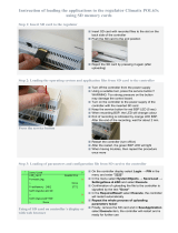
3.1. Hardware setup
This chapter describes how to configure and test your host PC, the development board with the
module (target) and how to start up the target for the first time.
Step 1: Connect serial port
Connect COM1 of the host PC to Serial Port 1 on the development board (target) using a standard
serial modem cable, included in the kit. The serial connection is used to communicate with the
target device.
Step 2: Connect Ethernet interface
Establish the Ethernet connection by connecting an Ethernet crossover cable directly to the
development board’s Ethernet port and your host PC. Alternatively, if you already have a running
network configuration, you can connect the development board to your hub or switch.
Step 3: Configure HyperTerminal
Configure HyperTerminal to view the console output the target prints on the serial interface.
To configure HyperTerminal, go to Start > Programs > Accessories > Communications >
HyperTerminal
Figure 3-1: HyperTerminal
Enter the name of the session and click OK.

ConnectCore XP 270 Board Support Package for Windows CE 5.0 - Installation and User's Guide
9
Figure 3-2: HyperTerminal (connection description)
Select the host PC’s serial port (the one you connected the serial cable to) :
Figure 3-3: HyperTerminal (serial port)
Finally, configure the serial parameters for 38400 bits per second, no parity, 8 data bits, 1 stop bit
and no flow control.

ConnectCore XP 270 Board Support Package for Windows CE 5.0 - Installation and User's Guide
10
Figure 3-4: HyperTerminal (serial parameters)
Step 4: Connect power
Connect the power supply to the development board. As the board powers up, the LEDs will light.
Approximately 2-4 seconds later the system will print boot messages on the console.
After 30-35 seconds, when the boot loader has unpacked and launched the pre-installed Windows
CE kernel from the module’s built-in Flash memory, you will see output on the terminal client similar
to the following:
U-Boot 1.1.3 (Nov 9 2005 - 10:02:07) FS.2
for FS Forth-Systeme CCXP270 on STK2
U-Boot code: A0090000 -> A00B2F74 BSS: -> A00F4324
RAM Configuration:
Bank #0: a0000000 64 MB
Bank #1: a4000000 0 kB
Bank #2: a8000000 0 kB
Bank #3: ac000000 0 kB
Flash: 32 MB
In: serial
Out: serial
Err: serial
Detecting SMSC LAN91C111 Ethernet Controller...
Revision ID: 0x01
Chip ID: 0x09
SMSC LAN91C111 detected...
Get MAC Address from 1-wire EEPROM
MAC Address from EEPROM : 00:04:F3:00:38:10
Initializing ethernet...
Using MAC Address 00:04:F3:00:38:10
Hit any key to stop autoboot: 0
## Starting application at 0xA0100000 ...
Step 5: Test Ethernet configuration
The target uses a default IP address on the 192.168.42.x network. We recommend that you
configure a dedicated Windows CE development network separate from your standard network.
Simply add and configure an additional network interface card to your PC and use an IP address
from the 192.168.42.0 subnet, e.g. 192.168.42.1.

ConnectCore XP 270 Board Support Package for Windows CE 5.0 - Installation and User's Guide
11
The target network parameters can be changed in the U-Boot bootloader using the "setenv"
command.
On the target you can see the IP address by going to Windows CE Start > Settings > Network and
Dial-up Connections. Double click the LAN91C111_1 network interface to configure the network
parameters:
Figure 3-5: Network configuration dialog
3.2. Software installation
First you have to install Microsoft Platform Builder 5.0 from the original Microsoft Windows CE 5.0
DVD/CD. If you use Microsoft Windows 2000, note the following:
Before you install Platform Builder under Windows 2000 you
must install Windows 2000 Service Pack 4 and the .NET
Framework.
During the installation of Platform Builder you must select ARMV4I and XSCALE as CPU support;
without it the BSP installation will fail.
If you are using Windows 2000 and have Internet Explorer 5.0 or earlier, you
may receive a Java error message when opening Platform Builder. Updating
Internet Explorer to the latest version will fix this issue.
Once you have installed Platform Builder, start the Setup.exe on the CD of the BSP and follow the
instructions. A wizard will guide you through the installation process. The wizard will install the
BSP, QFEs, and SDK by default; however, you can install additional files like the Cygwin tool chain
or the U-Boot bootloader sources.

ConnectCore XP 270 Board Support Package for Windows CE 5.0 - Installation and User's Guide
12
Figure 3-6: BSP Installation
The installation of the BSP will copy the following files and folders to your hard drive:
File/Folder Path Description
CCXP.CEC %_WINCEROOT%\public\common\oak\catalog\cec WinCE 5.0 components file
CCXP %_WINCEROOT%\Platform Platform files and drivers
CCXP %_WINCEROOT%\Platform\Common\Src\ARM\Intel Platform specific code
Kerneljoin.exe %_WINCEROOT%\public\common\oak\misc\
Program to generate raw
binary file
KernelCopy.bat %_WINCEROOT%\public\common\oak\misc\
Copies raw binary file into
TFTP server folder
bpostmakeimg.bat %_WINCEROOT%\public\common\oak\misc\
Start to generate and copy
raw binary file
ConnectCoreXP.xml
%_WINCEROOT%\public\common\oak\catalog\newplatfor
mwizards\
Example template shown in
this documentation
Table 3-1: Files and folders copied during installation
%_WINCEROOT% is an environment variable of your system that stands for the
path to your Windows CE 5.0 root directory (Usually C:\WINCE500)

ConnectCore XP 270 Board Support Package for Windows CE 5.0 - Installation and User's Guide
13
4. Building the First Image
4.1. Creating the platform
From Platform Builder File menu, select New Platform.
Enter the name of the project you want to create. Select Next.
From the available Board Support Packages (BSPs) select the CCXP platform and click Next.
Figure 4-1: Select BSP
Step 4 allows you to select a design template or custom device configuration for your platform.
Select ConnectCore XP 270 to create a standard CCXP based project.
Figure 4-2: Design template

ConnectCore XP 270 Board Support Package for Windows CE 5.0 - Installation and User's Guide
14
Selecting "Custom Device" lets you choose individual components for your
project.
In the following steps (5 -20) you can configure the components and programs that your final
Windows CE image will contain. If you have selected the ConnectCore XP 270 template project,
you can either click finish or walk through the configuration step-by-step.
If additional components are needed, Platform Builder will automatically include them in the build.
In this example we will create a kernel for the CCXP development board with support for the
hardware. There are two server applications: a Telnet server for remote control of the device and
an FTP server for uploading/downloading of files.
Step 5: Applications & Services Development
From the .NET Compact Framework, select OS Dependencies for .NET Compact Framework 1.0
and .NET Compact Framework 1.0.
Figure 4-3: Application and Services Development
With .NET Framework, support applications can be written with Visual Studio .NET 2003 for smart
devices in Visual Basic or C#.
Step 6: Applications – End User components
For this example we won’t need any of these; click Next.

ConnectCore XP 270 Board Support Package for Windows CE 5.0 - Installation and User's Guide
15
Step 7: Core OS Services
Select USB Host support (USB HID Keyboard and Mouse), Display Support and Serial Port
Support, then click Next. If you want to build an image with display support, select the display
component. You may also remove it from the project later if needed.
Figure 4-4: Core OS Services
The USB Host, serial port, and Display Windows CE drivers will be included. The registry keys to
configure them are stored in the file %_WINCEROOT%\Platform\CCXP\Files\Platform.reg
Step 8: Communication services and Networking
Under Networking Features, select Network Utilities (ipconfig, ping, …) and Windows Networking
API/Redirect. Under Networking – Local Area Network (LAN) you must include the Wired Local
Area Network (802.3, 802.5) to have support for your Ethernet interface. Under Servers select
Telnet Server and FTP Server. With the Telnet Server, you will be able to connect to the Windows
CE device shell from anywhere in your network.
To use the internal USB controller, you need to make a
hardware modification of the StarterKitII hardware. With this
modification you will lose the option to load kernel images
from a USB stick.

ConnectCore XP 270 Board Support Package for Windows CE 5.0 - Installation and User's Guide
16
Figure 4-5: Communication services and Networking
Some registry information has been included for the FTP and the TELNET servers in the file
%_WINCEROOT%\Platform\CCXP\Files\Platform.reg.
; TELNET SERVER
[HKEY_LOCAL_MACHINE\COMM\TELNETD]
"IsEnabled"=dword:1
"UseAuthentication"=dword:0 ;Don’t use authentication
; FTP SERVER
[HKEY_LOCAL_MACHINE\COMM\FTPD]
"IsEnabled"=dword:1
"UseAuthentication"=dword:0 ;Don’t use authentication
"AllowAnonymous"=dword:1 ;Allow anonymous login
"AllowAnonymousUpload"=dword:1 ;Allow anonymous upload of files
"DefaultDir"="\\" ;Root directory
These registry keys give you complete access to your target via
TELNET and FTP, for demonstration purposes. In order to
preserve the security of your targets, change these registry
keys by enabling the UseAuthentication key and adding a list of
allowed users.
For more information about security, read the chapters Telnet
Server Authentication and Security Considerations of Windows
CE on-line help.
Step 9: Device Management
Click Next.
Step 10: Storage Manager
In order to support any storage device used on your platform, you must include the support for the
FAT File System.

ConnectCore XP 270 Board Support Package for Windows CE 5.0 - Installation and User's Guide
17
Figure 4-6: FAT File System and Data Store
Step 11: Fonts
Select support for fonts. Click Next.
Step 12: Language
Select support the different languages. Click Next.
Step 13: Browser Application
Select Pocket Internet Explorer then click Next.
Figure 4-7: Internet Client Appication
/