Page is loading ...

Opteva® 740 ATM
Operating Guide
TP-820896-001F PD 5685
December 2010

Copyright protection is claimed for each revision listed in the document history, as of the date indicated.
Any trademarks, service marks, product names or company names not owned by Diebold Nixdorf, Incorporated,
formerly known as Diebold, Incorporated or its subsidiaries (collectively “Diebold Nixdorf”) that appear in this
document are used for informational purposes only and Diebold Nixdorf claims no rights thereto, nor does such use
indicate any affiliation with or any endorsement of Diebold Nixdorf or Diebold Nixdorf products by the owners
thereof.
This document contains proprietary information. If the document pages state the information is confidential
(or words of similar import), then this document is intended solely for the use of the copyright owner's
employees or other personnel expressly authorized in writing by the copyright owner. Other uses of this
information without the express written consent of the copyright owner are prohibited. This document should
be treated as confidential material for security reasons. Any unauthorized disclosure or use of confidential
material may violate Section 1832 of Title 18 of the United States Code as well as other laws, and may be
punishable by fine and imprisonment.
The information contained in this document is subject to change without notice. When using the document for system
implementation, please call your authorized sales or service representative for any applicable changes.
This document and the information contained herein are provided AS IS AND WITHOUT WARRANTY. In
no event shall the copyright owner or its suppliers be liable for any special, indirect, or consequential damages
of any nature resulting from the use of information in this manual.
No part of this document may be reproduced, stored in a retrieval system, or transmitted, in any form or by any
means: electronic, mechanical, photocopying, recording, or otherwise, without prior written permission from the
copyright owner.
Your use of this document and/or any of the information contained herein constitutes your agreement to all of the
terms stated on this page.
Diebold Nixdorf continually strives to improve its products. If you would like to comment on the accuracy, clarity,
organization or value of this document, please contact us at documentationservices@dieboldnixdorf.com or address
correspondence to:
Diebold Nixdorf, Inc.
Att: Documentation Services 9-B-16
5995 Mayfair Road
North Canton, OH 44720
ii
Copyright ©Diebold, Incorporated (8/2003, 12/2003, 3/2005, 9/2007, 4/2008, 12/2010) - All Rights Reserved
TP-820896-001F

Document History
Document Number Date Remarks
TP-820896-001A 8/2003 Original Edition
TP-820896-001B 12/2003 Figure 2-1 and Figure 2-2: added new headphone jack location
Section 2.2.1: added information about the graphical printer
Section 2.2.2: added caution on internal AC outlets, and
updated Figure 2-19
Table A-1: updated manual information
TP-820896-001C 3/2005 Figure 2-1, Figure 2-2, and Figure 2-5: added graphical printer
information
Figure 2-1, Figure 2-2, Figure 2-4, and Figure 2-7: added
fifth-generation intelligent depository module information
Appendix A: updated document information
TP-820896-001D 9/2007 Added Appendix A and general update
TP-820896-001E 4/2008 Section 2.2.1: Added intelligent depository module bulk
document (IDM-BD) and bulk note acceptor information
Section 2.2.2: updated with terminal power push button
Section 2.3.4: updated with free-fall cassette
Added Section 2.3.5, Opteva stacking cassette module (OSC)
TP-820896-001F 12/2010 Add the CEN-L safe information.
Figure 2-1 change the envelope depositor bezel
Figure 2-21, View B: add a CEN-L safe figure
Figure 2-28, View B : add the CEN -L safe door locks and
handles.
Figure 3-1 , Figure 3-2, Figure 3-6: change figure into terminal
with CEN-L safe.
Figure 3-3, View B: add the CEN-L safe door locks and handles
information.
Figure 3-4, View B, Figure 3-5, View B: add the CEN-L safe
opening information
iii
Copyright ©Diebold, Incorporated (8/2003, 12/2003, 3/2005, 9/2007, 4/2008, 12/2010) - All Rights Reserved
TP-820896-001F

Contents
Section1 Introduction ............................................ 1-1
1.1 BeforePerformingMaintenanceProcedures .......................... 1-1
1.2 MaintenanceTasks ....................................... 1-1
1.3 UsingthisManual ........................................ 1-2
1.4 ObservingSafetyPrecautions .................................. 1-2
1.5 TaiwanClassARadioInterferenceLabel ........................... 1-3
1.6 Terminology ........................................... 1-4
Section2 ATMDevices ........................................... 2-1
2.1 DevicesandAccessPointsontheFascia ............................ 2-1
2.1.1 ConsumerInterface .................................. 2-1
2.1.2 Lead-throughIndicators ................................ 2-6
2.2 DevicesintheTopChassis ................................... 2-7
2.2.1 DevicesUsedbytheConsumer ............................ 2-7
2.2.2 DevicesUsedbytheOperator ............................. 2-22
2.3 DevicesintheSafe ....................................... 2-30
2.3.1 Dispenser ........................................ 2-33
2.3.2 Divert/RetractCassetteandDivertBin ........................ 2-34
2.3.3 DispenseCassettes ................................... 2-35
2.3.4 BulkNoteAcceptorFree-FallCassette ........................ 2-36
2.3.5 Opteva Stacking Cassette Module (OSC) for the Bulk Note Acceptor ........ 2-37
2.3.6 DepositCassettes ................................... 2-40
2.3.7 SecureSafeDoorLock ................................. 2-41
2.3.8 AlarmsSensors ..................................... 2-44
2.3.9 SeismicDetectors ................................... 2-44
2.3.10 HeatThermostat .................................... 2-45
Section3 MaintenanceProceduresfortheTopChassisandSafe ...................... 3-1
3.1 ATMandDeviceTouchPoints ................................. 3-2
3.2 OpeningtheTopChassis .................................... 3-4
3.3 AccessingtheSafe ....................................... 3-5
3.3.1 OpeningSafeDoorswithMechanicalCombinationLocks .............. 3-7
3.3.2 Closing and Securing Safe Doors with Mechanical Combination Locks . . . . . . . 3-10
3.3.3 OpeningSafeDoorswithElectronicCombinationLocks ............... 3-11
3.3.4 ClosingandSecuringSafeDoorswithElectronicCombinationLocks ........ 3-13
3.4 PositioningtheRearOperatorDisplayandMaintenanceKeyboard .............. 3-14
3.4.1 ExtendingtheRearOperatorDisplayandMaintenanceKeyboard .......... 3-15
3.4.2 ChangingtheAngleoftheMaintenanceKeyboard .................. 3-17
AppendixARelatedDocumentation ...................................... A-1
AppendixBCleaningtheExterioroftheTerminal .............................. B-1
Figures
Figure1-1 TaiwanClassALabel ...................................... 1-3
Figure 2-1 Opteva 740 Fascia Features (without bulk note acceptor) .................... 2-4
Figure2-2 Opteva740FasciaFeatures(withbulknoteacceptor) ..................... 2-5
iv
Copyright ©Diebold, Incorporated (8/2003, 12/2003, 3/2005, 9/2007, 4/2008, 12/2010) - All Rights Reserved
TP-820896-001F

Figures
Figure2-3 Lead-throughIndicators ..................................... 2-6
Figure2-4 DevicesintheTopChassis(withoutbulknoteacceptor) .................... 2-8
Figure2-5 DevicesintheTopChassis(withbulknoteacceptor) ...................... 2-9
Figure2-6 BarCodeScanner ........................................ 2-10
Figure2-7 Fifth-generationIntelligentDepositoryModule(IDMV) .................... 2-11
Figure2-8 BulkDocumentIntelligentDepositoryModule(IDM-BD) ................... 2-12
Figure2-9 MotorizedCardReader ..................................... 2-13
Figure2-10 DipCardReader ......................................... 2-14
Figure 2-11 Graphical Receipt Printer (80 mm) . . . . . . ......................... 2-15
Figure 2-12 Graphical Receipt Printer (112 mm) ............................... 2-16
Figure2-13 StatementPrinter ......................................... 2-17
Figure2-14 BulkNoteAcceptor ....................................... 2-19
Figure 2-15 Bulk Note Acceptor Access . . ................................. 2-20
Figure2-16 EnvelopeDepositor(withintegrateddispenser) ......................... 2-21
Figure2-17 DevicesintheTopChassisUsedbytheOperator ........................ 2-23
Figure2-18 RearOperatorDisplayandMaintenanceKeyboard ....................... 2-24
Figure 2-19 Maintenance Mode Switch, Disk Drive Assemblies, Terminal Power Push Button, and AC
Outlets. .............................................. 2-27
Figure2-20 JournalPrinter .......................................... 2-29
Figure2-21 SafeDevices ........................................... 2-31
Figure2-22 Dispenser ............................................. 2-33
Figure2-23 Divert/RetractCassetteandDivertBin ............................. 2-34
Figure2-24 DispenseCassettes ........................................ 2-35
Figure2-25 BulkNoteAcceptorFree-FallCassette ............................. 2-36
Figure 2-26 Opteva Stacking Cassette Module (OSC) for the Bulk Note Acceptor . . . . . . ....... 2-37
Figure2-27 DepositCassettes ........................................ 2-40
Figure2-28 SafeDoorLocks ......................................... 2-42
Figure2-29 SeismicDetector ......................................... 2-44
Figure2-30 HeatThermostat ......................................... 2-45
Figure3-1 TouchPointExamples(CEN-Lsafeshown) .......................... 3-2
Figure3-2 OpeningtheTopChassis(CEN-Lsafeshown) ......................... 3-4
Figure3-3 SafeDoorLocksandHandles .................................. 3-6
Figure3-4 OpeningSafeDoorswithMechanicalCombinationLocks ................... 3-8
Figure3-5 OpeningSafeDoorswithElectronicCombinationLocks .................... 3-11
Figure3-6 RearOperatorDisplayandMaintenanceKeyboard ....................... 3-14
Figure3-7 Left-facingExtendedPosition .................................. 3-15
Figure3-8 Rear-facingandRight-facingExtendedPositions ........................ 3-16
Figure3-9 AdjustingthePositionoftheMaintenanceKeyboard ...................... 3-18
Tables
TableA-1 RelatedDocumentation ..................................... A-1
v
Copyright ©Diebold, Incorporated (8/2003, 12/2003, 3/2005, 9/2007, 4/2008, 12/2010) - All Rights Reserved
TP-820896-001F

Section 1
Introduction
The Opteva® 740 ATM is a full-service terminal that allows consumers to
deposit and receive cash, obtain transaction records, and perform other financial
tasks available on a full-service ATM.
The ATM has the following characteristics:
• Installed through the exterior wall of a building in locations with motor
vehicle access, such as bank buildings
• Has a weather-resistant design
• Supplies are replenished from the rear of the ATM
• Maintenance is performed from the front and the rear of the terminal
1.1 Before Performing Maintenance Procedures
You should be familiar with the following information before performing the
maintenance procedures in this manual:
• The features and equipment on your ATM
• The maintenance option your institution has selected for its ATM(s)
Standard and Optional Equipment
Depending on the requirements of your institution, your ATM might not have
all the features described in this manual. Refer to the documents listed in
Appendix A for more information about standard and optional equipment.
Maintenance Options
Your institution can select from several maintenance options; determine which
option your institution has selected before servicing the ATM. Your ATM
manager or supervisor can provide this information.
1.2 Maintenance Tasks
Maintenance keeps the ATM operational on a day-to-day basis and includes, but
is not limited to, the following tasks:
• Retrieving jammed, retained or captured cards from the card reader
• Replenishing printer paper, clearing paper jams and replacing printer
cartridges
• Removing jammed cash from cash dispensing or cash accepting modules
1-1
Copyright ©Diebold, Incorporated (8/2003, 12/2003, 3/2005, 9/2007, 4/2008, 12/2010) - All Rights Reserved
TP-820896-001F

1.3 Using this Manual
This manual provides the following information:
• A description of devices used in the ATM (Section 2)
• Maintenance procedures for the top chassis and safe (Section 3)
• Related documentation (Appendix A).
• Cleaning the exterior of the ATM (Appendix B)
1.4 Observing Safety Precautions
General Safety Precautions
Strictly observe the following safety precautions during maintenance. By
following these precautions, you can reduce the risk of equipment damage,
severe personal injury, or death.
You must observe the following precautions when performing
maintenance on the ATM to avoid risk of death, severe
personal injury, or equipment damage:
• Do not wear loose clothing or jewelry that can become
caught in the equipment.
• Use caution to prevent long hair from getting caught in
the equipment.
• Never insert screwdrivers, pens, or other instruments
into any ATM module or device (unless you are expressly
instructed to do so in this document). Severe bodily
injury, death from electrical shock, or equipment damage
can result.
• Always turn off the ATM before removing or installing
modules.
1-2
Copyright ©Diebold, Incorporated (8/2003, 12/2003, 3/2005, 9/2007, 4/2008, 12/2010) - All Rights Reserved
TP-820896-001F

WarningandCautionLabels
The ATM might have any of the warning or caution labels shown below. Strictly
observe the following safety concerns to reduce the risk of severe personal
injury, or death.
Label Definition Safety Concern
Electrical shock
hazard
An electrical shock hazard exists in the area
of the label. Do not remove covers. Remove
power before servicing.
Warning or danger
A personal injury can occur. Look for nearby
warning label (electrical shock, pinch point,
moving machinery, high temperature hazard)
or refer to the module or ATM operating
guideforthespecific hazard.
Pinch point
An area that can pinch (or cut) you exists in
the area of this label. Keep your hands and
fingers clear of pinch points.
Moving machinery
hazard
Moving parts that can snag or pull clothing,
hair, skin, or jewelry into the mechanism
are present in the area of this label. Keep
clothing, hair, skin, and jewelry out of the
mechanism.
High temperature
hazard
High temperatures that can cause pain or
burns are present in the area of this label.
Do not touch until cooled.
1.5 Taiwan Class A Radio Interference Label
A warning label (Figure 1-1) is included on ATMs available in Taiwan to meet
Taiwan Class A regulatory requirements for radio frequency interference.
m29094u
Figure 1-1 Taiwan Class A Label
1-3
Copyright ©Diebold, Incorporated (8/2003, 12/2003, 3/2005, 9/2007, 4/2008, 12/2010) - All Rights Reserved
TP-820896-001F

1.6 Terminology
This document uses the following terms:
•ATM refers to the complete Opteva 740 terminal.
•Note(s) refers to the documents of monetary value that are stored in the
cassettes and dispensed from the dispenser.
•Consumer refers to any person who uses the ATM to transact business.
•Device refers to the small and large electrical and mechanical components
that make up the ATM.
•Dispenser refers to the module that takes media from the cassettes and
transports it through a slot in the fascia to the consumer.
•Fascia refers to the front portion of the ATM, including the area where the
consumer transacts business.
•Institution refers to any bank or business that might purchase the ATM.
•Maintenance refers to the routine tasks performed by the operator to keep
the ATM operational.
•Media refers to any type of document (such as a bank note, bill, ticket,
coupon, etc.) that is stored in the cassettes and and dispensed from the
dispenser.
•Module refers to the major electro-mechanical devices that make up the
ATM, such as displays, printers, and dispensers.
•Operator refers to a person who performs routine maintenance tasks, such as
replenishing supplies. The operator might also resolve common problems,
such as removing paper jams.
1-4
Copyright ©Diebold, Incorporated (8/2003, 12/2003, 3/2005, 9/2007, 4/2008, 12/2010) - All Rights Reserved
TP-820896-001F

Section 2
ATM Devices
This section describes the devices available on the Opteva 740 ATM. These
devices are located in either the top chassis or in the safe. For more information
about individual devices, refer to the documents listed in Appendix A.
NOTE
Your ATM might not contain all the devices described in this
section. Some devices are optional and some devices cannot
be used in combination with other devices, such as mutually
exclusive combinations.
2.1 Devices and Access Points on the Fascia
The consumer selects transactions, specifies amounts, deposits bills and
documents, receives dispensable media, and receipts, and requests information
at the fascia.
2.1.1 Consumer Interface
The consumer interface provides an access point for consumer devices or
features. The labels on many of the access points explain how to use the device
and lighted indicators guide the consumer through the transaction sequence.
The consumer interface includes the following features and interfaces (your
ATM might not have all these features).
NOTE
The locations for some of the items might vary, depending on
the devices and features that are installed in the ATM. See
Figure 2-1 and Figure 2-2 for the various fascia configurations.
Fascia Lighting
A light located near the top of the fascia illuminates the fascia. An optional
lighted signage panel, which includes an exterior fluorescent light and cover,
can be mounted on top of the fascia.
Speakers
Speakers in the top of the fascia can guide consumers through the transaction.
MotorizedCardReaderSlot
To use the motorized card reader, the consumer inserts an ATM card in the card
slot to begin a transaction. The card reader automatically pulls the card into the
ATM and returns the card when the transaction is completed.
2-1
Copyright ©Diebold, Incorporated (8/2003, 12/2003, 3/2005, 9/2007, 4/2008, 12/2010) - All Rights Reserved
TP-820896-001F

Dip Card Reader
To use the dip card reader, the consumer inserts an ATM card in the card slot
and then removes the card to begin a transaction. The dip card reader can read
magnetic stripe cards and memory chip cards. The dip card reader cannot retract,
capture, or retain cards.
Bar Code Scanner
The consumer places the bar code that is printed on certain materials, such as
utility bills, on the scanner shelf. The bar code scanner above the shelf reads the
bar code for information about the account.
Consumer Keypad
During the transaction sequence, the ATM prompts the consumer to use the
consumer keypad to enter transaction information. The 16-key keypad uses a
security module and encrypting PIN pad technology to secure the information
entered by the consumer at the keypad.
Function Keypads
There are four keys on each side of the consumer display. The consumer presses
the function key that corresponds to an option on the consumer display.
Consumer Display
The consumer display welcomes the consumer and provides instructions for
performing transactions. An optional touch screen display eliminates the need
for function keypads.
Headphone Jack
Visually impaired consumers can plug headphones into a jack on the fascia to
receive voice guidance. The fascia speakers do not function when the headphone
jack is being used.
Camera Window
The fascia has a window for an optional camera security system.
Printer Slot
At the end of a transaction, the consumer receives a printed record through the
printer slot.
2-2
Copyright ©Diebold, Incorporated (8/2003, 12/2003, 3/2005, 9/2007, 4/2008, 12/2010) - All Rights Reserved
TP-820896-001F

Envelope Depositor Slot
The consumer obtains envelopes and makes deposits through the envelope
depositor slot. The deposited envelopes are transported to a secure cassette inside
the safe.
Intelligent Depositor Module (IDM) Slot
The consumer deposits single checks without envelopes through the slot for
the intelligent depositor module. The intelligent depositor module scans the
check for information about the account and the amount data and then stores the
checks in an open bin.
Intelligent Depository Module Bulk Document (IDM-BD) Slot
The consumer deposits a stack of up to 30 documents through the intelligent
depository module bulk document (IDM-BD) slot. Documents can be inserted
face up or face down with the short edge first. The intelligent depository module
scans the check for information about the account and the amount data and then
stores the checks in an open bin.
Dispenser Slot
Bank notes and other media are presented to the consumer through the dispenser
slot.
Bulk Note Acceptor Opening
The consumer can deposit unbound stacks of notes into the opening for the bulk
note acceptor. The notes are first validated and acceptable notes are stored in a
secure cassette inside the safe.
2-3
Copyright ©Diebold, Incorporated (8/2003, 12/2003, 3/2005, 9/2007, 4/2008, 12/2010) - All Rights Reserved
TP-820896-001F

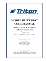
1 Lighted signage panel
2Fasciat
ask light
3Intelligent depository module slot (IDM V or IDM-BD)
4Camera window
5Receipt printer or graphical printer slot
6Headphone jack (can be in either position, depending on installed components)
7 Motorized card slot
8 Dip card reader
9 Envelope depositor slot
10 Bar code scanner
11 Speakers (mounted on inside of fascia)
12 Dispenser slot
13 Consumer keypad
14 Receipt printer or graphical printer slot
15 Statement printer slot
16 Function keypad
17Consumer display
Figure 2-1 Opteva 740 Fascia Features (without bulk note acceptor)
2-4
Copyright ©Diebold, Incorporated (8/2003, 12/2003, 3/2005, 9/2007, 4/2008, 12/2010) - All Rights Reserved
TP-820896-001F

1 Lighted signage panel
2 Fascia task light
3Intelligent depository module slot (IDM or IDM-BD)
4Camera window
5Receipt printer or graphical printer slot
6Headphone jack (can be in either position, depending on installed components)
7 Bulk note acceptor opening
8 Motorized card slot
9 Dip card reader
10 Bar code scanner
11 Speakers (mounted on inside of fascia)
12 Dispenser slot
13 Consumer keypad
14 Receipt printer or graphical printer slot
15 Statement printer slot
16 Function keypad
17Consumer display
Figure 2-2 Opteva 740 Fascia Features (with bulk note acceptor)
2-5
Copyright ©Diebold, Incorporated (8/2003, 12/2003, 3/2005, 9/2007, 4/2008, 12/2010) - All Rights Reserved
TP-820896-001F

2.1.2 Lead-through Indicators
Lead-through indicators (Figure 2-3) guide the consumer through the transaction
by calling attention to the next step in the sequence. These indicators display
three single colors: red, green, or yellow. Lead-through indicators are provided at
the following access points:
• Dip card reader
• Envelope depositor (with integrated dispenser)
•Dispenser
• Receipt printer
• Statement printer
• Intelligent depository module (IDM V or IDM-BD)
• Bulk note acceptor
1 Lead-through indicator example
Figure 2-3 Lead-through Indicators
2-6
Copyright ©Diebold, Incorporated (8/2003, 12/2003, 3/2005, 9/2007, 4/2008, 12/2010) - All Rights Reserved
TP-820896-001F

2.2 Devices in the Top Chassis
There are two types of devices in the top chassis:
• Devices used by the consumer (Section 2.2.1)
• Devices used by the operator (Section 2.2.2)
NOTE
Your ATM might not contain all the devices described in this
section. Some devices are optional and some devices cannot
be used in combination with other devices, such as mutually
exclusive combinations.
2.2.1 Devices Used by the Consumer
The following devices in the top chassis can be used by the consumer:
• Dip card reader or motorized card reader
• Intelligent depository module (IDM)
• Intelligent depository module bulk document (IDM-BD)
• Receipt printer
• Graphical printer
• Statement printer
• Bulk note acceptor
• Envelope depositor (with integrated dispenser)
• Bar code scanner
The location of these devices is shown in Figure 2-4 and Figure 2-5 (see
Figure 2-1 and Figure 2-2 for the location of the bar code scanner). The following
paragraphs contain a brief description of each device.
NOTE
Additional consumer interface devices are located on the ATM
fascia assembly. Refer to Section 2.1.1 and see Figure 2-1 and
Figure 2-2 for information about these devices.
2-7
Copyright ©Diebold, Incorporated (8/2003, 12/2003, 3/2005, 9/2007, 4/2008, 12/2010) - All Rights Reserved
TP-820896-001F

1Statement printer, graphical printer, or receipt printer (receipt printer shown)
2Intelligent depository module (IDM V or IDM-BD), receipt printer, or
graphical printer (intelligent depository module shown)
3 Motorized card reader
4Envelope depositor (with integrated dispenser)
Figure 2-4 Devices in the Top Chassis (without bulk note acceptor)
2-8
Copyright ©Diebold, Incorporated (8/2003, 12/2003, 3/2005, 9/2007, 4/2008, 12/2010) - All Rights Reserved
TP-820896-001F

1Statement printer, graphical printer, or receipt printer (statement printer shown)
2Intelligent depository module (IDM or IDM-BD), receipt printer, or graphical
printer (receipt printer shown)
3 Motorized card reader
4 Bulk note acceptor
Figure 2-5 Devices in the Top Chassis (with bulk note acceptor)
2-9
Copyright ©Diebold, Incorporated (8/2003, 12/2003, 3/2005, 9/2007, 4/2008, 12/2010) - All Rights Reserved
TP-820896-001F

Bar Code Scanner
The bar code scanner (Figure 2-6) reads and decodes bar codes, which are used
during a transaction for tracking and routing purposes.
The consumer places the bar code of a document, such as a utility bill, on the
scanner shelf. The beam from the scanner reads the bar code and processes the
information.
Refer to the Consumer Bar Code Scanner Operating Guide (TP-820813-001A)
for more information.
Figure 2-6 Bar Code Scanner
2-10
Copyright ©Diebold, Incorporated (8/2003, 12/2003, 3/2005, 9/2007, 4/2008, 12/2010) - All Rights Reserved
TP-820896-001F

Fifth-generation Intelligent Depository Module
The intelligent depository module (Figure 2-7) reads information from a check
and deposits the amount into the consumer's account. The intelligent depository
module does not accept envelopes. After the intelligent depository module reads
the check, it is transported to a bin at the rear of the module.
Refer to the Fifth-generation Intelligent Depository Module Operating Guide
(TP-820903-001C) for more information.
Figure 2-7 Fifth-generation Intelligent Depository Module (IDM V)
2-11
Copyright ©Diebold, Incorporated (8/2003, 12/2003, 3/2005, 9/2007, 4/2008, 12/2010) - All Rights Reserved
TP-820896-001F
/