Page is loading ...

INSTALLATION AND PROGRAMMING GUIDE
1134 Wireless Access
Control Module


About the 1134 ............................................ 1
Power Supply ......................................................... 1
Zone Terminals ...................................................... 1
Annunciators .......................................................... 1
Indicator LEDs ....................................................... 1
Form C Relay ......................................................... 2
Programming Connection ................................ 2
Dry/Wet Contact ................................................. 2
Built-In LED Survey ............................................. 2
PCB Features ...............................................3
Program the 1134 ........................................4
Device Setup ......................................................... 4
Zone Information ................................................. 5
Install the 1134 ............................................6
Select a Location ................................................. 6
Mount the 1134 ...................................................... 7
Wire the Access Control Lock ........................ 8
Isolation Relay (optional) ................................10
TABLE OF CONTENTS
Install the 333 Suppressor ............................... 11
Wire the Zone Terminals .................................. 12
Connect a Wiegand Card Reader ................14
Connect the Power Supply .............................17
Program the 1134 ...................................... 18
Programmer Menu .............................................19
Serial Number Dispay ......................................................19
Initialization Options .........................................19
Access Options ..................................................20
Activate Zone 2 Bypass .................................................20
Activate Zone 3 Request to Exit .................................22
Activate Onboard Speaker ...........................................23
Card Formats ..................................................................... 23
Require Site Code ............................................................ 27
Number of User Code Digits .......................................28
Card Format Added/Changed (Custom Format) 28
No Communication with Panel ...................................29
Remove Keypad ................................................ 30
Public Card Formats ................................ 31

Certifications .............................................32
Product Specifications ............................33
Readers and Credentials ........................ 34
FCC Information ...................................... 36
Industry Canada Information ..................37
Compatibility ............................................38

Digital Monitoring Products, Inc. | 1134 Installation and Programming Guide 1
Annunciators
An onboard programmable piezo provides
local annunciation at the 1134. You can
also connect a variety of switched ground
annunciators to the 1134 for remote
annunciation.
Indicator LEDs
The 1134 provides three indicator LEDs:
• RELAY (red) turns on for the same
duration as the door strike relay.
• WIEGAND (yellow) turns on for one
second to indicate receipt of valid input.
• SURVEY (red) indicates signal strength
to the wireless receiver.
The 1134 Wireless Access Control Module allows you to use the powerful, built in access
control capability of DMP Panels using smartcard, proximity, mag stripe, or biometric
readers, or other compatible authentication devices. The 1134 includes the following
features:
Power Supply
The 1134 operates at 12/24VDC from
the power supply supporting a door’s
magnetic lock or door-strike.
Warning: To avoid the risk of
equipment damage, do not exceed
750mA total output current for
zones connected to the module.
Zone Terminals
Zones 1 - 4 on the 1134 can be
programmed for a variety of burglary or
access control applications.
ABOUT THE 1134

2 1134 Installation and Programming Guide | Digital Monitoring Products, Inc.
Form C Relay
The 10Amp Form C relay draws up to
35mA of current. Refer to “Wire the
Access Control Lock” and “Isolation Relay
(optional)” in this document for more
information.
Programming Connection
The 1134 also provides a keypad
programming connection that allows
you to use a standard DMP LCD keypad
for initial setup. Programming can be
completed using a keypad connected
to the 1134 or from XR150/XR550 Series
panels.
Dry/Wet Contact
Apply 12 VDC power from the module
directly to the door relay (WET setting)
or connect the relay to a separate power
supply (DRY setting).
Built-In LED Survey
The 1134provides survey LED capability
that allows one person to confirm
communication with the panel and
receiver while the cover is removed.

Digital Monitoring Products, Inc. | 1134 Installation and Programming Guide 3
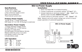
PCB FEATURES
Figure 1: PCB Features
1
2
3
4 5 6 7
8
10
11 12 13 14
9
LC ASRED WHTGRN BLK Z1 Z2 Z3 Z4RA GND GND
NC
C
NO
SURVEY
WIEGAND
RELAY
PROG
RESET
TAMPER
DISABLE
SURVEY
GND
DRY
WET
LED
Survey
Button
Piezo
Wiegand
Inputs
Status
Indicator
Outputs
Zones
Reset
Tamper
LED
Indicators
Keypad
Programming
Header
Power
Supply
Door
Relay
Terminal
Dry/Wet
Contact

4 1134 Installation and Programming Guide | Digital Monitoring Products, Inc.
PROGRAM THE 1134
Refer to the panel programming guide as needed.
1. Reset the panel.
2. At the keypad, enter 6653 (PROG) to access the PROGRAMMER menu.
Device Setup
1. In DEVICE SETUP, press CMD until you get to DEVICE NO: -.
2. Enter a DEVICE NO:- and press CMD.
3. Enter a DEVICE NAME and press CMD.
4. (XT30/XT50 only) Select YES when WIRELESS? displays.
5. Select DOOR for DEVICE TYPE and press CMD.
6. (XR150/XR550 only) Select WLS at COMM TYPE and press CMD.
Note: Panel version 191 or higher software is required.
7. Enter the eight-digit SERIAL# that starts with 14 (SN1) and press CMD.
8. Enter the SUPRVSN TIME and press CMD.

Digital Monitoring Products, Inc. | 1134 Installation and Programming Guide 5
Zone Information
1. In ZONE INFORMATION, enter the wireless ZONE NO: - and press CMD.
2. Enter the ZONE NAME and press CMD.
3. Select the ZONE TYPE and press CMD.
4. At NEXT ZN?, select NO.
5. Select YES when WIRELESS? displays.
6. Enter the eight-digit SERIAL# that starts with 08 (SN2) and press CMD.
7. Enter the CONTACT number being used.
8. Enter the SUPRVSN TIME and press CMD.
9. At the NEXT ZN? prompt, select YES and continue to program up to three more
zones. Additional zones must be entered sequentially. See Table 1.
Panel Zones
XT30/XT50,
XTLplus,
& XTLtouch
The zone numbers begin with the 1134 address and are followed by the particular
zone from the 1134. For example, an 1134 at keypad address 4 would provide
zones 41, 42, 43, and 44.
XR150 Zone numbers are valid from 500-599.
Zones must still be programmed sequentially (i.e. 551, 552, 553, and 554).
XR550 Zone numbers are valid from 500-999.
Zones must still be programmed sequentially (i.e. 551, 552, 553, and 554).
Table 1: Zone Information

6 1134 Installation and Programming Guide | Digital Monitoring Products, Inc.
INSTALL THE 1134
1
Select a Location
1. With the cover removed, hold the module in the desired location.
2. Press the survey button to send a signal to the panel and determine if
communication is confirmed or faulty.
Confirmed: For each press of the survey button, the transmitter LED
blinks immediately on and immediately o. The LED remains o when
the transmitter is synced with the panel. Repeat this test to confirm five
separate consecutive LED blinks. Any indication otherwise means proper
communication has not been established.
Faulty: If communication is faulty, the transmitter LED remains on for
about 8seconds or flashes multiple times in quick succession.
3. If the transmitter is not communicating with the panel, start by confirming
that it is correctly wired and programmed, then look for items that might
cause interference such as large metal objects or electronic equipment.
Relocate the transmitter or receiver until the LED confirms clear
communication.

Digital Monitoring Products, Inc. | 1134 Installation and Programming Guide 7
Mount the 1134
The module comes in a high-impact plastic housing that you can mount directly to
a wall, backboard, or other flat surface.
For easy installation, the back and ends of the 1134 housing have wire entrances.
The back also contains multiple mounting holes that allow you to mount the
module on a single-gang switch box. DMP recommends mounting the 1134 near the
protected door. Refer to Figure 2 for mounting hole locations on the housing base.
2
1. Remove the PCB from the
plastic housing by loosening
the clips on one side and
gently lifting it out of the
housing base.
2. Insert the included screws in
the desired mounting hole
locations and tighten them
to secure the housing to the
surface.
3. Reinstall the PCB in the
housing base.
Mounting Holes
Figure 2: Mounting Hole Locations

8 1134 Installation and Programming Guide | Digital Monitoring Products, Inc.
Wire the Access Control Lock
The 1134 provides a Form C (SPDT) relay for controlling locks and other
electronically-controlled barriers. The three relay terminals marked NO C NC allow
you to connect the device wiring to the relay for module control. See Figure 3,
Figure 4, and Figure 5 for typical magnetic lock and door strike wiring.
The Form C relay draws up to 35mA of current and contacts are rated for 10Amps
(resistive) at 12/24VDC.
When connecting multiple locks to the Form C relay, the total current for all locks
cannot exceed 10Amps. If the total current for all locks exceeds 10Amps, problems
may arise and an isolation relay may be needed. Refer to “Isolation Relay (optional)”
for more information.
When the jumper on the 1134 is set to WET, up to 750mA 12VDC will pass though
the Cterminal and no additional power supply is needed.
2

Digital Monitoring Products, Inc. | 1134 Installation and Programming Guide 9
Model 333
Suppressor
–+
12/24 VDC
Power Supply
Normally Closed
Magnetic Door
Lock
Mag lock positive
to Terminal NC
Power supply positive
to Terminal C
Mag lock negative to
power supply negative
Figure 3: Typical Magnetic Lock Wiring
Model 333
Suppressor
–+
12/24 VDC
Power Supply
Normally Open
Door strike positive
to Terminal NO
Power supply positive
to Terminal C
Door strike negative to
power supply negative
DC Door Strike
Figure 4: Dry Door Strike Wiring
Model 333
Suppressor
–+
Normally Open
Door strike positive
to Terminal NO
Door strike negative to
module DC negative
DC Door Strike
Figure 5: Wet Door Strike Wiring

10 1134 Installation and Programming Guide | Digital Monitoring Products, Inc.
Isolation Relay (optional)
The Form C relay can control a device that draws less than 10Amps of current. If a
device draws more than 10Amps of current, or the sum of all devices controlled by
the Form C relay exceeds 10Amps, an isolation relay must be used. Refer to Figure 6
and Figure 7 for isolation relay wiring.
3
5 6
7
8
10
11 12 13 14
9
LC
AS Z1 Z2 Z3 Z4
RA
GND GND
NC
C
NO
Model 333
Suppressor
Normally Open
–+
Magnetic Lock
–+
Isolation Relay
12/24 VDC
Power
Supply
NCCNO
GND
Figure 6: Magnetic Lock with
an Isolation Relay
5 6 7
8
10
11 12 13 14
9
LC
AS Z1 Z2 Z3 Z4RA GND GND
NC
C
NO
Model 333
Suppressor
Normally Open
–+
DC Door Strike
–+
Isolation Relay
12/24 VDC
Power
Supply
NCCNO
GND
Figure 7: Door Strike with
an Isolation Relay

Digital Monitoring Products, Inc. | 1134 Installation and Programming Guide 11
Install the 333 Suppressor
Use the included 333 suppressor with
the 1134 to suppress any surges caused
by energizing a magnetic lock or door
strike.
Install the 333 across the module’s C
(common) and NO (normally open) or
NC (normally closed) terminals.
If the device being controlled by the
relay is connected to the NO and C
terminals, install the suppressor on the
NO and C terminals.
Conversely, if the device is connected to
the NC and C terminals, install the 333
Suppressor on NC and C terminals.
The suppressor wire is non-polarized.
Install the suppressor as shown in
Figure 8.
4
Figure 8: 333 Suppressor
Installation on the 1134
7
8
10
11 12 13 14
9
AS
Z1 Z2 Z3 Z4GND GND
NC
C
NO
GND

12 1134 Installation and Programming Guide | Digital Monitoring Products, Inc.
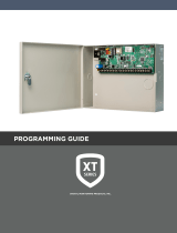
Wire the Zone Terminals
Terminals 8 through 14 connect grounded zones1 through 4. These zones have a
grounded side and cannot be used for fire-initiating devices. Zones 2 and 3 can
also be used for access control with zone2 providing a bypass feature and zone3
providing request to exit functionality.
Use the supplied 311 1k Ohm End-of-Line (EOL) resistors on each zone. Refer to the
panel programming guide for programming instructions. See Table 2 and Figure 9
for more information on wiring the zone terminals.
5

Digital Monitoring Products, Inc. | 1134 Installation and Programming Guide 13
1
2
3
4 5 6 7
8
10
11 12 13 14
9
LC ASRED WHTGRN BLK Z1 Z2 Z3 Z4RA GND GND
NC
C
NO
GND
Zone 1
Zone 3
Zone 4
1k Ω EOL
Zone 2
1k Ω EOL
1k Ω EOL
1k Ω EOL
Figure 9: Zone Terminal Wiring
Table 2: 1134 Zone Uses
Zone 3 can also
be wired normally
closed with an
in‑line 1k Ohm
resistor
Zone # Recommended Device Residential Fire Device?
1 Any burglary device No
2 Door contact No
3 REX (PIR or Button) No
4 Any Device No

14 1134 Installation and Programming Guide | Digital Monitoring Products, Inc.
Connect a Wiegand Card Reader
The 1134 provides direct 12/24VDC, 200mA output to the reader on the Red
terminal connection. Figure 10 shows a reader with wire colors RED, WHT, GRN,
and BLK connecting to Terminals 1, 2, 3, and 4.
The green wire carries Data Zero (D0), and the white wire carries Data One (D1).
The red wire connects 12/24VDC, 200mA maximum power and the black wire is
ground.
The wire colors may be dierent depending on the reader being installed. Refer to
the literature provided with the reader for wire coding, wire distance, cable type
(such as shielded), and other specifications.
Wiegand Status Indicator Outputs
Terminals 5, 6, and 7 provide connections for Remote LED Control, Remote
Annunciation, and Armed Status indicators.
6

Digital Monitoring Products, Inc. | 1134 Installation and Programming Guide 15
LC (Remote LED Control)
Remote LED Control provides an unsupervised switched ground for a visual indicator
that turns on when the relay activates. Connect the wire from the LC Terminal to an
LED. The LED turns on for the duration the door strike relay is on. HID readers optionally
provide a connection for LED reader control.
LC Wire Color LED Color
Orange Green
Brown Red
RA (Remote Annunciation)
Remote Annunciation provides an unsupervised switched ground for a remote
annunciator that turns on when the Zone 2Bypass timer expires. Connect the wire from
the RA Terminal to a remote annunciator. The remote annunciator silences when the RA
restores. The remote annunciator (RA) switched ground operates even if the speaker is
programmed not to operate.
AS (Armed Status)
Armed Status provides an unsupervised switched ground for a visual or audible armed
status indicator that turns on when the burglary areas are armed, such as SYSTEM ON or
ALL SYSTEM ON. Connect a wire from the AS Terminal to an armed status indicator.
Caution: Status indicator outputs support a maximum of 100mA per terminal.
Exceeding the maximum rating on LC, RA, or AS terminals can damage equipment.

16 1134 Installation and Programming Guide | Digital Monitoring Products, Inc.
Figure 10: Wiegand Card Reader Wiring
Red (12/24VDC)
Black (GND)
Orange or Brown
Yellow
Green (Data 0)
Wiegand
Card Reader
White (Data 1)
1
2
3
4 5 6 7
8
10
11 12 13 14
9
LC ASRED WHTGRN BLK Z1 Z2 Z3 Z4RA GND GND
GND
/