XR150/550 ACCESS LAB GUIDE
Instructor-Led Training
IDENTIFY PANEL COMPONENTS
1. Identify the following panel components using the
panels in front of you, or the on-screen photo of the
XR.
ê Reset header
ê Programming
header
ê Outputs
ê AC Power terminals
ê Cellular pins
ê 1100 Series antenna
connection
ê On-board zone
terminals
ê Network connection
POWER UP THE CONTROL PANEL
1. Connect AC power to terminals 1 & 2
ê Transformer type: 16.5VAC 50VA
2. Connect battery backup to terminals 3 & 4
3. Connect alarm bell to terminals 5 & 6
ê Normal 12VDC is supplied to terminal 5, terminal 6 is ground reference
ê 1/2 W 1K Ohm resistor should be added across the bell circuit for supervision
ENTER PANEL PROGRAMMER
1. Reset the panel using the RESET JUMPER
2. Enter 6653 (PROG) and press CMD
3. Press CMD to navigate through the panel programmer
menus:
ê Initialization
ê Communication
ê Network Options
ê Messaging Setup
ê Device Setup
ê Remote Options
ê System Reports
ê System Options
ê Bell Options
ê Output Options
ê Output Information
ê Output Groups
ê Status List
ê Menu Display
ê PC Log Reports
ê Area Information
ê Zone Information
ê Stop
EDIT AREA NAMES
1. Press CMD to navigate to AREA INFORMATION
2. Press a top-row select area to enter AREA
INFORMATION
3. Enter an AREA NUMBER and press CMD
4. Press CMD until EXIT DELAY displays
5. Press a top row select key or area and enter a time
between 45 and 250 seconds
6. Press a top-row select area to clear any text and enter
in a new area name
7. Exit AREA INFORMATION and navigate to STOP to
save changes
8. Arm, disarm and trip an alarm in Area system type
CREATE A SCHEDULE
1. At the keypad, press CMD until the USER MENU?
prompt displays
2. Select YES and enter 99+CMD to enter the USER
MENU
3. Using CMD, navigate to SCHEDULES? and press a
top-row select area
4. Select TIMES
5. To create a time schedule, select ADD
6. Press 1 to create Schedule 1
7. Press a top row area to enter a name for the schedule
8. Press CMD and select a day of the week.
9. Enter the BEGIN and END times for the chosen day
10. Set times for each day of the week
11. Create schedule 2
CREATE A PROFILE
1. At the keypad, press CMD until the USER MENU?
prompt displays
2. Select YES and enter 99+CMD to enter the USER
MENU
3. Using CMD, navigate to PROFILES? and press a top-
row select area
4. Select ADD and enter 11 to create PROFILE 11
5. Press a top row area to enter a name for the profile
6. Assign ARM/DISARM AREA 2 and press CMD
7. Assign ACCESS AREA 2 and press CMD
8. Press CMD until DISARM? displays and select YES
9. Navigate to DOOR ACCESS and confirm it is set to
YES
10. Navigate to FIRST ACCESS SCHEDULE and press the
third select area to enter the schedule number for the
access schedule
11. LIST will show the schedule names
12. Press CMD until PROFILE 11 ADDED is displayed
13. Create another profile using PROFILE 12
ADD A USER CODE WITH PIN
1. Enter the USER MENU and navigate to the USER
CODES? prompt
2. Press a top-row select area to add a USER CODE
3. Select ADD
4. Select the USER NUMBER and press CMD
ê The fourth top row select area will display the lowest available user number
5. Enter in a 5-digit user code and press CMD
6. Press a top-row select area to add a USER NAME and
press CMD
7. Press a top row select area, enter 12 to assign
PROFILE 12 to this user
ê LIST will display the profile names
8. Press CMD until USER ADDED displays

ADD A USER CODE WITH CARD
1. Enter the USER MENU and go to USER CODES?
2. Press a top-row select area to add a USER CODE
3. Select ADD
4. Select the USER NUMBER and press CMD
5. Scan card by waving it over the blue status LED
6. Press a top-row select area and add a USER NAME
and press CMD
7. Press a top-row select area and enter 11 to assign
PROFILE 11 to this user.
8. Press CMD until USER ADDED displays
CREATE AN OUTPUT SCHEDULE
1. Re-enter the schedule programming section. Press
CMD and select OUTPUT.
2. Enter output 1, then schedule 2.
3. Press the BACK ARROW to exit schedule
programming.
4. Advance panel TIME to test the BEGIN and END times
for the schedule.
ADD A 734 INTERFACE MODULE
1. Connect the 734 module to the KEYPAD BUS
2. Use the dip switches on the 734 to address the
module
3. Reset the panel and enter 6653 (PROG) to enter the
panel programmer
4. Using CMD, navigate to DEVICE SETUP
5. Program the 734 at the same address set with the dip
switches
6. Press a top-row select area to name the device
7. Press a top-row select area to program the DEVICE
TYPE as a DOOR
8. Assign ACCESS AREA 2
9. Set PUBLIC DOOR, FIRE EXIT, and DOOR REAL-TIME
STATUS to YES
10. Connect the reader to TERMINALS 1–4 on the 734
11. Connect the POSITIVE terminal on the external power
supply to the C (Common) terminal on the 734
12. Connect the NEGATIVE terminal on the door strike to
the NEGATIVE terminal on the external power supply
13. Connect the POSITIVE terminal on the door strike to
the NO (Normally Open) terminal on the 734
14. Install the Model 333 Suppressor between the C and
NO terminals on the 734
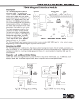
ADD A 734N/734N-POE
The 734N and 734N-POE only have one dierence and
that is how they are powered. To program a 734N/734N-
POE, programming needs to take place in two places: the
panel and the 734N/734N-POE.
PANEL PROGRAMMING
1. Reset the panel and enter 6653 (PROG) to enter the
panel programmer
2. Using CMD, navigate to NETWORK OPTIONS
3. Write down the PANEL IP ADDRESS
4. Write down the 734N LISTEN PORT and make sure it
is open to the local network
5. Press a top-row select area to set the 734N
PASSPHRASE
6. Using CMD, navigate to DEVICE SETUP
7. Program a DEVICE NUMBER for the 734N
ê For AX-Bus use, the 734N must be at least v101 (10/21/16)
8. Press a top-row select area to name the device
9. Assign ACCESS AREA 2 to the device
10. Set PUBLIC DOOR, FIRE EXIT, and DOOR REAL-TIME
STATUS to YES
WIRING/734N PROGRAMMING
1. Connect the 734N to the local network
ê For 734N-POE connect network cable to a POE switch
2. Connect the reader to TERMINALS 1-4
3. Connect DC power
ê The 734N accepts 12-24VDC power input
4. Plug a keypad into the PROG header on the 734N
ê The keypad should be Address 1 with supervision turned on
5. Press CMD to navigate to 734N COMMUNICATION
and press a top-row select key
6. Program the DEVICE NUMBER for the 734N
ê This should match the device that was created in the panel
7. If entering STATIC IP information, set DHCP to NO,
otherwise, press CMD
ê The 734N requires an IP, subnet mask, and gateway address for static network
programming
8. Enter the PANEL IP PORT
ê This should match the 734N Listen Port from the panels’ programming
9. Enter the 734N PASSPHRASE that was entered in the
panel
10. Program access options for this door
11. Using CMD, advance to STOP and press a top-row
select key to save programming
12. Remove the keypad from the PROG header
13. Connect the POSITIVE terminal on the external power
supply to the C (Common) terminal on the 734N
14. Connect the NEGATIVE terminal on the door strike to
the NEGATIVE terminal on the external power supply
15. Connect the POSITIVE terminal on the door strike to
the NO (Normally Open) terminal on the 734N
16. Install the Model 333 Suppressor between the C and
NO terminals on the 734N
ADD A CUSTOM CARD FORMAT
PANEL PROGRAMMING
1. Reset the panel and enter 6653 (PROG) to enter the

panel programmer
2. Using CMD, navigate to DEVICE SETUP
3. Press a top-row select key to enter DEVICE SETUP
4. Press a top-row select key to enter CARD FORMATS
5. Enter 1 then CMD to program the first card format
6. Press a top-row select key to name the format DMP
39 bit
7. Press CMD to navigate to WIEGAND CODE LENGTH
8. Press a top-row select key to enter the length of 39
9. Press CMD to navigate to SITE CODE
10. Press a left top-row select key and enter 1 for SITE
CODE POSITION, then press CMD
11. Press a right top-row select key and enter 17 for SITE
CODE LENGTH, then press CMD
12. Press a left top-row select key and enter 18 for the
USER CODE POSITION, then press CMD
13. Press a right top-row select key and enter 20 for the
USER CODE LENGTH
14. Press CMD to advance to REQUIRE SITE CODE?
15. Press CMD to leave as NO, otherwise press a left top-
row key to change to YES, press CMD
16. Press a right top-row key and enter 7 at NUMBER OF
USER CODE DIGITS, then press CMD
17. At the Card Formats screen, press the back-arrow key
to return to CARD FORMATS
18. Press the back-arrow key again to return to DEVICE
SETUP
19. Using CMD, advance to STOP and press a top-row
select key to save programming
PROGRAM A 39 BIT CARD
1. Enter the USER MENU and go to USER CODES?
2. Press a top-row select area to add a USER CODE
3. Select ADD
4. Select the USER NUMBER and press CMD
5. Scan card by waving it over the blue status LED
6. Press a top-row select area and add a USER NAME
and press CMD
7. Press a top-row select area and enter 11 to assign
PROFILE 11 to this user
8. Press CMD until USER ADDED displays
ADD A 1134 WIRELESS WIEGAND
MODULE
To program a 1134, programming needs to take place in
two places: the panel and the 1134.
WIRING/DEVICE PROGRAMMING
1. Connect the POSITIVE terminal on the external power
supply to the POSITIVE terminal on the 1134
2. Connect the NEGATIVE terminal on the external
power supply to the NEGATIVE terminal on the 1134
3. Set the WET/DRY jumper to WET
4. Connect the POSITIVE terminal on the door strike to
the NO (Normally Open) terminal on the 1134
5. Connect the NEGATIVE terminal on the door strike to
the NEGATIVE terminal on the 1134
6. Install the Model 333 Suppressor between the C and
NO terminals on the 1134
7. Connect a door contact to Zone 2
8. Connect the REX to Zone 3
9. Connect the reader to TERMINALS 1-4
10. Plug in the keypad to the 1134 PROG header
ê The keypad should be Address 1 with supervision turned on
11. Using CMD, navigate to ACTIVATE ZONE 2 BYPASS
12. Press the fourth top-row select key to turn on
ZONE 2 BYPASS
13. Using CMD, navigate to ACTIVATE ZONE 3 REX
14. Press the fourth top-row select key to turn on
ZONE 3 REX
15. Using CMD, navigate to REMOVE KEYPAD and
remove the keypad from the PROG header
PANEL PROGRAMMING
1. Reset the panel and enter 6653 (PROG) to enter the
panel programmer
2. Using CMD, navigate to DEVICE SETUP
3. Press CMD until you get to DEVICE NO:-
4. Enter a DEVICE NO and press CMD
5. Press CMD until you get to DEVICE NAME
6. Enter a DEVICE NAME and press CMD
7. Select DOOR for DEVICE TYPE and press CMD
8. Select WLS at COMM TYPE and press CMD
ê Panel version 191 or higher software is required
9. Enter the eight-digit SERIAL NO and press CMD
ê Enter the Type 14 serial number labeled ‘Device’ found on the 1134 PCB or by connecting
a keypad to the header on the 1134
10. Enter the SUPRVSN TIME and press CMD
11. Program access options for this door
12. Using CMD, navigate to ZONE INFORMATION
13. Enter the wireless ZONE NO and press CMD
14. Enter the ZONE NAME and press CMD
15. Select the ZONE TYPE and press CMD
16. At NEXT ZN?, select NO
17. Select YES when WIRELESS? displays
18. Enter the eight-digit SERIAL # and press CMD
ê Enter the Type 08 serial number labeled ‘Zones’ found on the 1134 PCB or by connecting a
keypad to the header on the 1134
19. Enter the CONTACT number being used
ê Zone 1 is contact 1, zone 2 is contact 2, etc...
20. Enter the SUPRVSN TIME and press CMD
21. Using CMD, advance to STOP and press a top-row
select key to save programming
22. Remove the keypad from the PROG header
GIVE IT A TRY
1. Create a system with 2 Areas: Area 1: Oce, Area 2:
Warehouse
2. Create a new SCHEDULE with these parameters:

ê Days: Friday | Hours: 15 minute window
3. Create two PROFILES with these parameters:
ê Sta: Warehouse at Friday schedule | Admin: Full access at all times
4. Add a USER CODE with a proximity token for each of
the two profiles: Sta and Admin
5. Using the 734 Module named “Oce Door” on Device
2, ensure it allows access to both areas
6. Enable SCHEDULE OVERRIDE for Device 2
7. Apply SCHEDULE 2 to Device 2
8. Apply SCHEDULE 2 to the Sta profile
9. Change TIME & DATE in the USER MENU to
experiment with dierent schedule scenarios
QUESTIONS
What else would you like to learn about XR Series Access?
NOTES:
/
