Page is loading ...

INSTALLATION AND PROGRAMMING GUIDE
1134 Wireless
Wiegand Module


About the 1134 ............................................ 1
Power Supply ......................................................... 1
Zone Terminals ...................................................... 1
Annunciators .......................................................... 1
LED Indicators ....................................................... 1
LED Survey ............................................................ 2
Form C Relay ......................................................... 2
Programming Connection ................................ 2
Dry/Wet Contact ................................................. 2
PCB Features ...............................................3
Program the 1134 ........................................4
Part 1: Device Setup ............................................ 4
Part 2: Zone Information .................................. 5
Install the 1134 ............................................6
Mount the 1134 ...................................................... 6
Wire the Electronic Lock .................................. 7
Isolation Relay ...................................................... 9
Install the 333 Suppressor ..............................10
Wire the Zone Terminals ...................................11
Connect a Card Reader ....................................13
TABLE OF CONTENTS
Program the 1134 Options ....................... 15
Program Start Display ......................................15
Serial Number Display ......................................15
Initialization Option ...........................................15
Initialize Confirm Option .................................16
Activate Zone 2 Bypass ...................................16
Zone 2 Bypass Time .......................................... 17
Relock on Zone 2 Change ...............................17
Activate Zone 3 Request to Exit ..................18
Zone 3 REX Strike Time ...................................19
Activate Onboard Speaker .............................19
Custom Card Definitions ........................ 20
Any Card Format ...............................................20
Card Formats ......................................................20
Format Name ......................................................20
Wiegand Code Length .....................................21
Site Code Position and Length ....................22
User Code Position and Length ...................22
Require Site Code .............................................22
Site Code Display ..............................................23
Number of User Code Digits .........................23

No Communication with Panel ....................24
Remove Keypad ................................................. 25
Public Card Formats ............................... 26
Product Specifications ............................27
Readers and Credentials .........................28
FCC Information ...................................... 30
Industry Canada Information .................. 31

Digital Monitoring Products, Inc. | 1134 Installation and Programming Guide 1
ANNUNCIATORS
An on-board programmable piezo provides local
annunciation at the 1134. You can also connect a
variety of switched ground annunciators to the
1134 for remote annunciation.
LED INDICATORS
The 1134 provides two indicator LEDs. The
SURVEY (Red) LED turns on for the same
duration as the door strike relay. The WIEGAND
(Yellow) LED turns on for one second to indicate
receipt of a valid Wiegand input.
The 1134 Wireless Wiegand Module allows you to use the powerful built-in access control capability of
DMP panels. DMP panels provide access control, arming, and disarming using proximity, mag-stripe,
biometric or other Wiegand-output authentication devices.
The 1134 connects and operates wirelessly with DMP panels. A keypad may be plugged directly into
the 1134 for local programming. The 1134 includes the following features:
POWER SUPPLY
The 1134 operates at 12/24VDC from the power
supply supporting a door’s magnetic lock or
door-strikes. It also provides a 10 Amp Form C
relay contact for lock control.
ZONE TERMINALS
The 1134 has four onboard zones that can be
programmed for a variety of burglary or access
control applications.
ABOUT THE 1134

2 1134 Installation and Programming Guide | Digital Monitoring Products, Inc.
LED SURVEY
The 1134 provides a Survey LED capability to
allow one person to confirm communication with
the wireless receiver while the cover is removed.
Mount the 1134 away from large metal objects
because it may impair performance. Do not
mount the 1134 inside a metal enclosure or install
in a drop ceiling.
1. With the cover removed, hold the 1134 in the
exact desired location.
2. Press the tamper switch to send data to the
panel and determine if communication is
confirmed or faulty.
Confirmed: If communication is
confirmed, for each press or release of the
tamper switch, the LED blinks
immediately on and immediately o.
Faulty: If communication is faulty, the
LED remains on for about 8seconds or
flashes multiple times in quick succession.
Relocate the 1134 or receiver until the LED
confirms clear communication.
FORM C RELAY
The 1134’s Form C relay draws up to 35mA of
current. Refer to the NC/C/NO (Dry Contact
Relay) and the Isolation Relay sections in this
document for more information.
PROGRAMMING CONNECTION
The 1134 provides a keypad programming
connection that allows you to use a standard
DMP LCD keypad for initial setup.
DRY/WET CONTACT
Apply power to the door relay (WET setting) or
leave it unpowered (DRY setting).

Digital Monitoring Products, Inc. | 1134 Installation and Programming Guide 3
1
2
3
4 5 6 7
8
10
11 12 13 14
9
LC ASRED WHT GRN BLK Z1 Z2 Z3 Z4RA GND GND
NC
C
NO
SURVEY
WIEGAND
PROG
DRY
WET
RESET
TAMPER
DISABLE
SURVEY
GND
LED Survey
Button
Piezo
Wiegand
Inputs
Status
Indicator
Outputs
Zones
Reset
Tamper
LED
Indicators
Keypad
Programming
Header
Power
Supply
Door Relay
Terminal
Dry/Wet
Contact
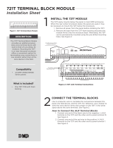
PCB FEATURES
Figure 1: PCB Features

4 1134 Installation and Programming Guide | Digital Monitoring Products, Inc.
PROGRAM THE 1134
Refer to the panel programming guide as needed.
1. Reset the panel.
2. At the keypad, enter 6653 (PROG) to access the PROGRAMMER menu.
PART 1: DEVICE SETUP
1. In DEVICE SETUP, press CMD until you get to DEVICE NO: -.
2. Enter a DEVICE NO:- and press CMD.
3. Enter a DEVICE NAME and press CMD.
4. (XT30/XT50 only) Select YES when WIRELESS? displays.
5. (XR150/XR550 only) Select DOOR for DEVICE TYPE and press CMD.
6. (XR150/XR550 only) Select WLS at COMM TYPE and press CMD.
Note: Panel version 191 or higher software is required.
7. Enter the eight-digit SERIAL#:- and press CMD.
Note: Enter the Type 14 serial number found on the 1134 PCB or by connecting a keypad to the
header on the 1134.
8. Enter the SUPRVSN TIME and press CMD.

Digital Monitoring Products, Inc. | 1134 Installation and Programming Guide 5
PART 2: ZONE INFORMATION
1. In ZONE INFORMATION, enter the wireless ZONE NO: - and press CMD.
2. Enter the ZONE NAME and press CMD.
3. Select the ZONE TYPE and press CMD.
4. At NEXT ZN?, select NO.
5. Select YES when WIRELESS? displays.
6. Enter the eight-digit SERIAL#:- and press CMD.
Note: Enter the Type 08 serial number found on the 1134 PCB or by connecting a keypad to the
header on the 1134.
7. Enter the CONTACT number being used.
8. Enter the SUPRVSN TIME and press CMD.
9. At the NEXT ZN? prompt, select YES and continue to program up to three more zones.
Note: Zones must be entered sequentially. For example, if you program zone 71, you need to
program zone 72 as the next contact. Use the same serial number for each contact.

6 1134 Installation and Programming Guide | Digital Monitoring Products, Inc.
INSTALL THE 1134
The 1134 comes in a high-impact plastic housing that you can mount directly to a wall, backboard,
or other flat surface.
For easy installation, the back and ends of the 1134 housing have wire entrances. The back also
contains multiple mounting holes that allow you to mount the 1134 on a single-gang switch box.
DMP recommends mounting the 1134 near the protected door. Remove the PCB from the housing
base to install the housing to the wall. See Figure2 for mounting hole locations.
1
MOUNT THE 1134
Mounting Hole
Figure 2: Mounting Hole Locations

Digital Monitoring Products, Inc. | 1134 Installation and Programming Guide 7
2
3
4 5 6 7
8
10
11 12 13 14
9
LC AS
RED WHT
GRN BLK Z1 Z2 Z3 Z4RA GND GND
NC
C
NO
Model 333
Suppressor
–+
DC Door Strike
12/24 VDC
Power Supply
Normally Open
GND
The 1134 provides a Form C (SPDT) relay for controlling locks and other electronically-controlled
barriers. The three relay terminals marked NO C NC allow you to connect the device wiring to
the relay for module control.
Use a power supply to power magnetic locks. See Figure 3. You can power door strikes either
from a power supply (DRY contact) or from the 1134 (WET contact). See Figures 4a and 4b for
door strike wiring.
The Form C relay draws up to 35mA of current and contacts are rated for 10Amps (resistive)
at 12/24VDC. When connecting multiple locks to the Form C relay, the total current for all locks
cannot exceed 10 Amps. If the total current for all locks exceeds 10 Amps, problems may arise
and an isolation relay may be needed. See the Isolation Relay section for information.
2
WIRE THE ELECTRONIC LOCK
2
3
4 5 6 7
8
10
11 12 13 14
9
LC AS
RED WHT
GRN BLK Z1 Z2 Z3 Z4RA GND GNDGND
NC
C
NO
Model 333
Suppressor
–
+
Magnetic Door Lock
12/24 VDC
Power Supply
Normally Closed
Figure 3: Typical
Magnetic Lock Wiring
Figure 4a: Dry Door
Strike Wiring

8 1134 Installation and Programming Guide | Digital Monitoring Products, Inc.
2
3
4 5 6 7
8
10
11 12 13 14
9
LC AS
RED WHT
GRN BLK Z1 Z2 Z3 Z4RA GND GND
NC
C
NO
Model 333
Suppressor
–+
DC Door Strike
Normally Open
GND
When the jumper on the 1134 is set to WET, the C terminal will pass 12VDC though the
Cterminal. No additional power supply is needed. See Figure4b.
Figure 4b: Wet
Door Strike Wiring

Digital Monitoring Products, Inc. | 1134 Installation and Programming Guide 9
The Form C relay can control a device that draws less than 10 Amps of current. If a device draws
more than 10 Amp of current, or the sum of all devices controlled by the Form C relay exceeds
10 Amps, an isolation relay must be used. Refer to Figures 5 and 6 for isolation relay wiring.
3
ISOLATION RELAY
5 6
7
8
10
11 12 13 14
9
LC
AS Z1 Z2 Z3 Z4
RA
GND GND
NC
C
NO
Model 333
Suppressor
Normally Open
–+
Magnetic Lock
–+
Isolation Relay
12/24 VDC
Power
Supply
NCCNO
GND
Figure 5: Magnetic Lock with
an Isolation Relay
5
6 7
8
10
11 12 13 14
9
LC
AS Z1 Z2 Z3 Z4RA GND GND
NC
C
NO
Model 333
Suppressor
Normally Open
–+
DC Door Strike
–+
Isolation Relay
12/24 VDC
Power
Supply
NCCNO
GND
Figure 6: Door Strike with
an Isolation Relay
(optional)

10 1134 Installation and Programming Guide | Digital Monitoring Products, Inc.
Use the included 333 suppressor with the
1134 to suppress any surges caused by
energizing a magnetic lock or door strike.
Install the 333 across the 1134 C (common)
and NO (normally open) or NC (normally
closed) terminals.
If the device being controlled by the relay is
connected to the NO and C terminals, install
the suppressor on the NO and C terminals.
Conversely, if the device is connected to
the NC and C terminals, install the 333
Suppressor on NC and C terminals.
The suppressor wire is non-polarized. Install
the suppressor as shown in Figure 7.
4
INSTALL THE 333 SUPPRESSOR
7
8
10
11 12 13 14
9
AS
Z1 Z2 Z3 Z4GND GND
NC
C
NO
GND
Figure 7: 333 Suppressor
Installation on the 1134

Digital Monitoring Products, Inc. | 1134 Installation and Programming Guide 11
Terminals 8 through 14 connect grounded zones 1 through 4. These zones have a grounded side
and cannot be used for fire-initiating devices. Zones 2 and 3 can also be used for access control
with zone 2 providing a bypass feature and zone 3 providing Request to Exit functionality.
Use the supplied 311 1K Ohm end-of-line (EOL) resistors on each zone. Refer to the panel
programming guide for programming instructions. See the table below and Figure 8 for more
information on wiring the zone terminals.
5
WIRE THE ZONE TERMINALS
ZONE # RECOMMENDED DEVICE
1 Any burglary device
2 Door Contact
3 REX (PIR or Button)
4 Any burglary device
Table 1: 1134 Zone Uses

12 1134 Installation and Programming Guide | Digital Monitoring Products, Inc.
1
2
3
4 5 6 7
8
10
11 12 13 14
9
LC ASRED WHT GRN BLK Z1 Z2 Z3 Z4RA GND GND
NC
C
NO
Zone 1
Zone 2
Zone 3
Zone 4
1K EOL
1K EOL
1K EOL
1K EOL
GND
Figure 8: 1134 Zone Terminal
Wiring

Digital Monitoring Products, Inc. | 1134 Installation and Programming Guide 13
The 1134 provides direct 12/24VDC, 200mA output to the reader on the RED terminal
connection. Figure 9 shows a reader with wire colors RED, WHT, GRN, and BLK connecting to
terminals 1, 2, 3, and 4.
The green wire carries Data Zero (D0), and the white wire carries Data One (D1). The red wire
connects 12/24VDC, 200mA maximum power and the black wire is ground.
The wire colors may be dierent depending on the reader being installed. Refer to the literature
provided with the reader for wire coding, wire distance, cable type (such as shielded), and other
specifications.
Card Reader LED Operation
To provide visual indication of a valid card read, the card reader can be wired to illuminate the
green LED for the duration of the door strike.
Connect the orange or brown wire to LC terminal 5 to have the green LED stay on for the
duration of the relay activation.
Card Reader Annunciation
Connect the yellow wire to RA terminal 6 to have the remote annunciator turn on anytime the
panel instructs the 1134 on-board piezo to turn on.
6
CONNECT A CARD READER
(optional)

14 1134 Installation and Programming Guide | Digital Monitoring Products, Inc.
Figure 9: Card Reader Wiring
1
2
3
4 5 6 7
8
10
11 12 13 14
9
LC ASRED WHT GRN BLK Z1 Z2 Z3 Z4RA GND GND
NC
C
NO
PROG
Card Reader
Red (12/24VDC)
White (Data 1)
Black (GND)
Green (Data 0)
Shield
Orange/Brown
Yellow
GND

Digital Monitoring Products, Inc. | 1134 Installation and Programming Guide 15
PROGRAM THE 1134 OPTIONS
When you program the 1134, you can use a keypad connected to the 1134 programming header and
set to address 1. For 12V applications, connect the keypad to the module using a Model 330 4-wire
harness. For 24V applications, connect the keypad to the module using a Model 330-24 4-wire
programming harness with in-line resistor.
Do not connect a keypad using a standard Model 330 harness if using a 24V power supply!
Damage to the keypad could occur.
While the 1134 is in programming mode, it will not be able to communicate with the panel.
PROGRAM START DISPLAY
When you connect the keypad to the 1134 module, the version number
and release date display. Press CMD to enter the PROGRAMMER
menu.
SERIAL NUMBER DISPLAY
View the serial numbers for the 1134. The 1134 has a Type14 and
Type08 serial number. Press CMD to view the second serial number.
INITIALIZATION OPTION
These options can set the 1134 module programming memory back to
factory defaults. Press any select key or area to enter the Initialization
menu.
1134 PROGRAMMING
VER VVV MM/DD/YY
SERIAL#:XXXXXXXX
INITIALIZE ALL?
NO YES

16 1134 Installation and Programming Guide | Digital Monitoring Products, Inc.
INITIALIZE CONFIRM OPTION
After selecting YES to clear the Access Options, the 1134 displays
SURE? YES NO for confirmation to clear the memory. This is a
safeguard against accidentally erasing the programming. No memory
is cleared from the programming until you answer YES to the SURE?
option. Selecting NO leaves communication options unchanged.
ACTIVATE ZONE 2 BYPASS
Select YES to activate the zone 2 bypass operation. Selecting NO
allows standard zone operation on zone 2. The default is NO.
If the door being released by the 1134 module is protected (contact
installed), a programmable bypass entry/exit timer can be provided
by connecting the contact wiring to the 1134 module zone 2. When
the on-board Form C relay activates and the user opens the door
connected to zone 2, the zone is delayed for the number of seconds
programmed in ZONE 2 BYPASS TIME allowing the user to enter/exit
during an armed period.
If zone 2 does not restore (door closed) within the programmed time,
the piezo sounds every other second during the last ten seconds.
If zone 2 restores prior to the end of the programmed time, the
piezo silences. If the zone does not restore before the programmed
time, the 1134 ends the bypass and indicates the open or short zone
condition to the panel.
ARE YOU SURE?
YES NO
ACTIVATE ZONE 2
BYPASS? NO YES
/