Page is loading ...

LT-2289 1.01 21293
X1 SERIES MULTI-DOOR ACCESS CONTROLLER
INSTALLATION AND PROGRAMMING GUIDE
© 2022

TABLE OF CONTENTS
X1 Series Multi-Door Access Controller
Overview ������������������������������������������������������������������ 1
X1 Door Controller Power ��������������������������������������������������� 1
X1 Door Controller PCB Components ���������������������������� 1
XD Door Control Module PCB Components �������������� 2
Door Controller Plug-In Terminals ���������������������������������� 2
Pre-Installation �������������������������������������������������������3
Step 1: Mount the Door Controller ����������������������3
Step 2: Connect a Card Reader ���������������������������3
Connect a Wiegand Card Reader ����������������������������������� 3
Connect an OSDP Card Reader �������������������������������������� 3
Optional Second Card Reader ����������������������������������������� 3
Step 3: Wire the Inputs ��������������������������������������� 4
Door Switch (DS) ������������������������������������������������������������������ 4
Request to Exit (RX) ������������������������������������������������������������4
Custom Input (CI) �����������������������������������������������������������������4
Ground (G)�������������������������������������������������������������������������������4
Step 4: Wire the Onboard Outputs ������������������� 4
Aux Output 1 & 2 (O1 & O2) ����������������������������������������������4
12V+ (12V) ��������������������������������������������������������������������������������4
Step 5: Wire the Electronic Lock ����������������������� 5
Form C Relay �������������������������������������������������������������������������� 5
Diode������������������������������������������������������������������������������������������ 5
Wet/Dry Jumper ������������������������������������������������������������������� 5
Step 6: Determine Communication ������������������� 6
Ethernet Connection �����������������������������������������������������������6
Cellular Connection (Optional) ����������������������������������������6
Wi-Fi Connection ������������������������������������������������������������������ 7
Step 7: Install Optional Output Module ������������ 8
X1 Output Module PCB Components ���������������������������� 8
Mount the X1 Output Module ������������������������������������������� 8
Address the X1 Output Module����������������������������������������9
Wire the X1 Output Module �����������������������������������������������9
Optional Additional Output Modules �������������������������� 10
Wire the Additional Output Modules ����������������������������11
Wire the Outputs �����������������������������������������������������������������12
Step 8: Apply Power ������������������������������������������� 13
Ground the Door Controller ���������������������������������������������13
Wire AC Power ���������������������������������������������������������������������� 13
Wire the Battery �������������������������������������������������������������������13
Wire the XD Door Control Modules ������������������������������13
Check the Addresses of the
XD Door Control Modules ����������������������������������������������� 14
Door Controller Wiring Example �����������������������������������15
XD Door Control Module Wiring Example �����������������16
Step 9: Manage Connection Settings �������������� 17
Configure Wi-Fi Settings ��������������������������������������������������17
Configure Network Settings ��������������������������������������������17
Configure Cell Settings ������������������������������������������������������17
Troubleshoot SSID Broadcast �����������������������������������������17
Step 10: Program in Dealer Admin ������������������� 18
Sign In to Dealer Admin ����������������������������������������������������18
Add a Customer �������������������������������������������������������������������18
Add the X1-8 Door Controller to the Customer �������18
Program the X1-8 Door Controller ��������������������������������19
Add Card Formats ���������������������������������������������������������������19
Add an X1 Output Module (Optional) ������������������������ 20
Enable Video Services ����������������������������������������������������� 20
Add an App User���������������������������������������������������������������� 20
Log In as a Customer ����������������������������������������������������������21
Step 11: Test the Door Controller ��������������������� 22
Additional Information ��������������������������������������� 22
LEDs �����������������������������������������������������������������������������������������22
Cell Module Removal ���������������������������������������������������������22
Door Controller Initialization �����������������������������������������22

X1-8 DOOR CONTROLLER INSTALLATION & PROGRAMMING GUIDE | DIGITAL MONITORING PRODUCTS 1
+AC/DC- +BAT- R1 W1 G1 B1 LC BC R2 W2 G2 B2 LC BC DS RX CI G 01 02 12V NC C NO
Power
Battery
In Reader
Out Reader
Inputs
Auxiliary Outputs
Door Relay
Wet/Dry Jumper
PWR/BOOT
READER 1
READER 2
RELAY
DATA
FIRE
LOCKDOWN
Operation LEDs
Ethernet Port
Cell Module Header
4-Wire Connector
A
B
D
E
F
G
H
I
J
K
L
M
AEF
GHIJKLMN
R and L Terminal
C
C
N
R
L
BD
Wi-Fi LED
X1 SERIES MULTI-DOOR ACCESS CONTROLLER OVERVIEW
The X1 Series is a cloud-based access door controller that is fully programmed in Dealer Admin™ and
maintained in Virtual Keypad™� This guide will cover mounting the door controller, wiring devices to the door
controller, configuring network options, applying power, programming the door controller in Dealer Admin,
and testing the door controller�
X1 Door Controller Power
Powered by: Maximum Current Draw:
Power Terminals 1�5 A
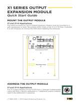
X1 Door Controller PCB Components
Refer to the diagram below throughout the installation�

X1-8 DOOR CONTROLLER INSTALLATION & PROGRAMMING GUIDE | DIGITAL MONITORING PRODUCTS 2
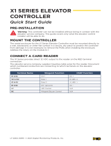
XD Door Control Module PCB Components
Refer to the diagram below throughout the installation�
0
1
2
3
4
5
6
7
8
9
0
1
2
3
4
5
6
7
8
9
R1 W1 G1 B1 LC BC R2 W2 G2 B2 LC BC DS RX CI G NC C NO
X1 and XD Headers
Out Reader
Address Rotary
Door Relay
A
B
D
E
F
Inputs
C
In Reader
A
EF
C
BD
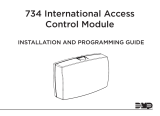
Door Controller Plug-In Terminals
Wiring terminals on an X1 Series Door Controller is done easily by using the
plug-in terminals�
1� Insert the wire into the slot�
2� Tighten the screw�
3� Snap the plug-in terminal onto the door controller board�
Plug In
1
2
3
Insert
Tighten

X1-8 DOOR CONTROLLER INSTALLATION & PROGRAMMING GUIDE | DIGITAL MONITORING PRODUCTS 3
STEP 2: CONNECT A CARD READER
The X1 Series provides connections for 2 readers� The first reader is designated for the In Reader and the
second is designated for the Out Reader�
The X1 Series Door Controller also provides direct 12 VDC output to the reader on the RED terminal
connection�
Terminal Name Wiegand Function OSDP Function
R1 & R2 12V+ DC +
W1 & W2 Data 1 B (485 +)
G1 & G2 Data 0 A (485 -)
B1 & B2 12V- (ground) DC -
LC LED Control N/A
BC Wiegand Buzzer Control N/A
Connect a Wiegand Card Reader
1� Connect the red wire (12 VDC) to terminal R1�
2� Connect the white wire (Data One) to W1�
3� Connect the green wire (Data Zero) to G1, black (ground) to B1�
4� Connect the orange or brown wire to LC�
Connect an OSDP Card Reader
1� For data transmission, connect the A wire (485 –) to the G1
terminal and the B wire (485 +) to the W1 terminal�
2� For reader power, connect the red wire (DC + ) to the R1 terminal and the black wire (DC –) to the B1
terminal�
Note: The wire colors may be different depending on the reader being installed� Refer to the literature
provided with the reader for wire coding, wire distance, cable type (such as shielded), and other
specifications� The figure above shows the DMP-preferred wiring�
Optional Second Card Reader
For an out reader, connect the red, white, green, and black wires to the Reader 2 terminals: R2, W2, G2, and
B2� Connect the orange/brown wire to LC�
If using only one reader, it must be connected to reader 1�
STEP 1: MOUNT THE DOOR CONTROLLER
The metal enclosure for the X1 Series must be mounted directly to a wall, backboard, or other flat surface in
a secure, dry place to protect the door controller from damage� Do not remove the PCBs from the enclosure�
Red
White
Green
Black
Orange/Brown
(Wiegand LED)
Card Reader
Reader 1 Terminals
R1 W1 G1 B1 LC BC
PRE-INSTALLATION
If the controller has been connected to a network prior to final installation, while connected to the network
delete the controller’s programming from Dealer Admin� Wait at least three minutes before disconnecting�
This allows the controller to initialize and return to factory settings�

X1-8 DOOR CONTROLLER INSTALLATION & PROGRAMMING GUIDE | DIGITAL MONITORING PRODUCTS 4
STEP 3: WIRE THE INPUTS
Door Switch (DS)
Connect a door contact or door position switch to indicate the status
of the door, whether it is open or closed� Use this terminal if enabling
door prop or door force�
This terminal is a Normally Closed input�
Request to Exit (RX)
Connect a motion sensing device or a mechanical switch to provide
RX capability to the door controller� RX can be used to activate
the door relay� When activated the RX activates the door lock relay
based on the programmed unlock time� Use this terminal if enabling
forced door�
This terminal is a Normally Open input�
Custom Input (CI)
This input triggers a rule through Virtual Keypad�
This terminal is a Normally Open input�
Ground (G)
This terminal is the ground for the inputs�
+AC/DC- +BAT- R1 W1 G1 B1 LC BC R2 W2 G2 B2 LC BC DS RX CI G01 02 12V NC C NO
DS RX CI G
STEP 4: WIRE THE ONBOARD OUTPUTS
Use these switches to ground outputs for local outputs or door alarms
such as sounders, lights, or sirens� These are 12 VDC outputs� For
example, a sounder could be wired for local indication of a door prop
or door force event�
Aux Output 1 & 2 (O1 & O2)
Attach the negative wire of the device here�
The relay contacts must be connected to devices located within 98�5 ft
(30m) of the door controller�
12V+ (12V)
Attach the positive wire of the device here� +AC/DC- +BAT- R1 W1 G1 B1 LC BC R2 W2 G2 B2 LC BC DS RX CI G 01 02 12V NC C NO
01 02 12V

X1-8 DOOR CONTROLLER INSTALLATION & PROGRAMMING GUIDE | DIGITAL MONITORING PRODUCTS 5
STEP 5: WIRE THE ELECTRONIC LOCK
Form C Relay
The X1 Series provides a Form C (SPDT) relay for controlling locks and other electronically-controlled
barriers� The three relay terminals marked NO C NC allow you to connect the device wiring to the relay for
module control�
The Form C relay draws up to 35 mA of current and contacts are rated for 1 Amp (resistive) at 12 VDC� When
connecting multiple locks to the Form C relay, the total current for all locks cannot exceed 1 Amp� If the total
current for all locks exceeds 1 Amp, problems will arise, it will not work as intended, and an isolation relay will
be required�
Diode
Connect the included diode as close to the magnetic lock or door strike as
possible to prevent inductive kickback� Observe polarity when connecting the
diode�
Wet/Dry Jumper
Putting the jumper on the top two terminals will place it in the dry condition and putting the jumper on the
bottom two terminals will place it in the wet condition� When using a dry relay, a power supply is needed to
power the lock/strike� When using a wet relay power is already supplied through the relay�
The X1-8 Door Controller is powered by the 505-12 Power Supply and is set up from the factory to utilize this
power supply to power the locks�
The XD Door Control Modules only wire dry because they do not have wet/dry jumpers�
Power Supply
Magnetic Lock positive
to Terminal NC
Power Supply positive
to Terminal C
Magnetic Lock negative to
Power Supply negative
NO
C
NC
Magnetic Lock - Normally Closed and Dry
DRY WET
Jumper set
to Dry
–+
Magnetic Lock
Diode
Magnetic Lock - Normally Closed and Wet
Magnetic Lock positive
to Terminal NC
Magnetic Lock negative to
X1 terminal B2
NO
C
NC
DRY WET
Jumper set
to Wet
Reader 2
–+
Magnetic Lock
B2
R2 W2 G2 LC BC
Diode
NO
C
NC
Door Strike - Normally Open and Dry
DRY WET
Jumper set
to Dry
Door Strike positive
to Terminal NO
Power Supply positive
to Terminal C
Door Strike negative to
Power Supply negative
–+
DC Door Strike
Power Supply
Diode
Door Strike - Normally Open and Wet
Door Strike positive
to Terminal NO
Door Strike negative to
X1 terminal B2
DRY WET
Jumper set
to Wet
Reader 2
–+
DC Door Strike
NO
C
NC
B2
R2 W2 G2 LC BC
Diode
+-
Positive Negative

X1-8 DOOR CONTROLLER INSTALLATION & PROGRAMMING GUIDE | DIGITAL MONITORING PRODUCTS 6
STEP 6: DETERMINE COMMUNICATION
The options in this section are in the DMP-recommended installation order� If an option is not part of your
desired application, move to the next option�
Ethernet Connection
Connect an Ethernet cable from the LAN/WAN connection to the X1 PCB
Ethernet port�
Two LEDs are located on the Ethernet port�
• The green LED indicates data is being sent over the network�
• The yellow LED indicates the speed of the transmission� A solid yellow
LED indicates the network is connected at 100BASE-T� A flashing
yellow LED indicates the network is connected at 10BASE-T�
Ethernet Port
Cellular Connection (Optional)
If the network cable or Wi-Fi are not connected, cell will be the primary communication� If the network cable
or Wi-Fi are connected, the cell will be the backup communication�
1� Plug the included standoff into the door controller board�
2� Plug the cell module onto the standoff�
3� Plug the cell module into the cell header�
4� Screw on the cell module antenna cable to the antenna connector�
5� Run the cable around the 505-12 Power Supply�
6� Attach the antenna with the nut on the inside of the enclosure and the washers on the inside and the
top of the enclosure�
Cell Antenna
Nut and Washer
X1-8 Enclosure
505-12 Power Supply
Cell Antenna Wire
5
6
Header
Cell Module
Stando
23
Door Controller
Cell
Antenna
Cable
Cell
Module
Door
Controller
4
Stando
Location
1
Once connected to an X1, the communicator will automatically register with the cellular carrier upon power
up�
Note: The cellular communicator comes pre-activated, so it cannot be activated through Dealer Admin,
Remote Link, or by calling Customer Service�

X1-8 DOOR CONTROLLER INSTALLATION & PROGRAMMING GUIDE | DIGITAL MONITORING PRODUCTS 7
Wi-Fi Connection
A Wi-Fi connection or a static IP address must be established after
power up� See Wi-Fi instructions later in this guide�
Note: You can connect over Ethernet or Wi-Fi, but not both at
the same time�
Wi‑Fi Antenna
The yellow Wi-Fi antenna connects to the right of the cell antenna
on the enclosure�
1� If the cable has become detached from the door controller,
simply wire it back onto the Wi-Fi module and run the cable
around the module�
2� Run the Wi-Fi cable around the 505-12 Power Supply and use
the included nut and washer to connect the antenna to the top
of the enclosure�
Nut and Washer
inside Enclosure
X1-8 Enclosure
Wi-Fi Antenna
505-12 Power Supply

X1-8 DOOR CONTROLLER INSTALLATION & PROGRAMMING GUIDE | DIGITAL MONITORING PRODUCTS 8
STEP 7: INSTALL OPTIONAL OUTPUT MODULE
X1 Door Controller
12 V Battery
+ -
-
+
0
1
2
3
4
5
6
7
8
9
Output Expansion Module
Mounting Holes
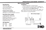
Mount the X1 Output Module
The metal enclosure for the X1 Output Expansion Module must
be mounted to a wall, backboard, or other flat surface within
3 feet of the X1 or X1-8 Door Controller� It is not necessary to
remove the PCB when installing the enclosure�
1
X1 Output Module PCB Components
Refer to the diagram below throughout the installation�
PWR
DATA
0
1
2
3
4
5
6
7
8
9
ADDR
6
1
7 8 9 10
2 3 4 5
NC 1 NO NC 2 NO NC 3 NO NC 4 NO NC 5 NO
NC 6 NO NC 7 NO NC 8 NO NC 9 NO NC 10 NO
Bottom 4-Wire Connector
Top 4-Wire Connector
Output Relay LEDs
Power LEDs
Address Rotary
A
B
C
D
A
BCD
RELAY RELAY RELAY
Output Relays
LED LED LED LED LED
LED LED LED LED LED
LED
RELAY RELAY
RELAY RELAY RELAY RELAY RELAY
RELAY

X1-8 DOOR CONTROLLER INSTALLATION & PROGRAMMING GUIDE | DIGITAL MONITORING PRODUCTS 9
Address the X1 Output Module
The X1 Output Module (X1-OUT-EXP) has a 1 through 9 addressable rotary dial that is
factory defaulted to 1� Additional output modules need to be addressed in sequence�
20
1
2
3
4
5
6
7
8
9
Output Expansion ModuleX1 Door Controller
12 V Battery
+ -
-
+
Wire the X1 Output Module
Use the included 4-position harness and enclosure knockouts to connect the top connector on the
output module to the bottom connector on the last XD Door Controller Module�
3
Output Expansion Module 1:
Address 1
100 VAC Wire-In
Transformer
0
1
2
3
4
5
6
7
8
9
0
1
2
3
4
5
6
7
8
9
0
1
2
3
4
5
6
7
8
9
0
1
2
3
4
5
6
7
8
9
0
1
2
3
4
5
6
7
8
9
0
1
2
3
4
5
6
7
8
9
0
1
2
3
4
5
6
7
8
9
Door Controller: Preset Address 1
Module 1: Address 2
Module 2: Address 3
Module 3: Address 4
Module 4: Address 5 Module 5: Address 6
Module 6: Address 7
Module 7: Address 8
Model 505-12
0
1
2
3
4
5
6
7
8
9
0
1
2
3
4
5
6
7
8
9
0
1
2
3
4
5
6
7
8
9
0
1
2
3
4
5
6
7
8
9
0
1
2
3
4
5
6
7
8
9
0
1
2
3
4
5
6
7
8
9
0
1
2
3
4
5
6
7
8
9
0
1
2
3
4
5
6
7
8
9
-
+
-
+
12 V Battery
+ -
-
+

X1-8 DOOR CONTROLLER INSTALLATION & PROGRAMMING GUIDE | DIGITAL MONITORING PRODUCTS 10
Optional Additional Output Modules
If not installing additional output
modules, skip to Step 6 Wire the
Outputs�
The metal enclosure for the X1 Output
Expansion Module comes with
mounting holes for two additional
X1 Output Module PCBs� To mount
the additional PCB, use the provided
standoffs and screw the PCB onto the
3 mounting holes�
4
0
1
2
3
4
5
6
7
8
9
First X1 Output Expansion Module
X1 Output Expansion Module
0
1
2
3
4
5
6
7
8
9
Second X1 Output
Expansion Module
Standos (3)
Screws (3)

X1-8 DOOR CONTROLLER INSTALLATION & PROGRAMMING GUIDE | DIGITAL MONITORING PRODUCTS 11
Output Expansion Module 1: Address 1
100 VAC Wire-In
Transformer
0
1
2
3
4
5
6
7
8
9
0
1
2
3
4
5
6
7
8
9
0
1
2
3
4
5
6
7
8
9
0
1
2
3
4
5
6
7
8
9
0
1
2
3
4
5
6
7
8
9
0
1
2
3
4
5
6
7
8
9
0
1
2
3
4
5
6
7
8
9
Door Controller: Preset Address 1
Module 1: Address 2
Module 2: Address 3
Module 3: Address 4
Module 4: Address 5 Module 5: Address 6
Module 6: Address 7
Module 7: Address 8
Model 505-12
0
1
2
3
4
5
6
7
8
9
0
1
2
3
4
5
6
7
8
9
0
1
2
3
4
5
6
7
8
9
0
1
2
3
4
5
6
7
8
9
0
1
2
3
4
5
6
7
8
9
0
1
2
3
4
5
6
7
8
9
0
1
2
3
4
5
6
7
8
9
0
1
2
3
4
5
6
7
8
9
-
+
-
+
12 V Battery
+ -
-
+
Output Expansion Module 2: Address 2
0
1
2
3
4
5
6
7
8
9
Wire the Additional Output Modules
If not installing additional output modules, skip to Step 6 Wire the Outputs�
Use the included 4-position harness to connect the top connector on the second output module to the
connector on the first output module�
5

X1-8 DOOR CONTROLLER INSTALLATION & PROGRAMMING GUIDE | DIGITAL MONITORING PRODUCTS 12
Wire the Outputs
To wire for output control, use the 10 terminals on
the output module�
The X1 Series Output Module provides 10 Form C
(SPDT) 1 Amp relays for controlling access to 10
outputs� The three relay terminals are labeled for
normally open (NO) and normally closed (NC)
operation� The center terminal is the common�
PWR
DATA
0
1
2
3
4
5
6
7
8
9
ADDR
6
1
7 8 9 10
2 3 4 5
NC 1 NO NC 2 NO NC 3 NO NC 4 NO NC 5 NO
NC 6 NO NC 7 NO NC 8 NO NC 9 NO NC 10 NO
NC 1 NO NC 1 NO
Normally Open Normally Closed
X1 Output Expansion Module
NC 1 NO
Normally Open
Common
Normally Closed
6

X1-8 DOOR CONTROLLER INSTALLATION & PROGRAMMING GUIDE | DIGITAL MONITORING PRODUCTS 13
STEP 8: APPLY POWER
Warning: Refer to your local state regulations before connecting to building power� Wiring methods
shall be in accordance with NEC, NFPA72, ANSI, and with all Authority Having Jurisdiction
Ground the Door Controller
Be sure to secure the green wire lead
to an earth ground� Connect to a
cold water pipe or ground rod when
available� Connection to an electrical
ground or conduit can also be used�
Gas pipes or sprinkler pipes should not
be used�
Wire AC Power
Connect an unswitched 120 V
AC 60Hz power source to the
transformer� Knockouts are supplied
for power input�
Wire the Battery
The battery leads for the X1-8 come pre-wired�
Connect the red battery lead to the battery
positive terminal� Connect the black battery lead
to the negative battery terminal� Observe polarity
when connecting the battery� For additional
power, use the 318 Battery Harness with additional
batteries wired in parallel�
Wire the XD Door Control Modules
The XD Door Control Modules come pre-wired and
addressed in the order shown here�
100 VAC Wire-In
Transformer
Output
16 VDC @ 100 VA
DC
Battery Wires
to Battery
12 VDC @ 5 Amps
BAT
To X1 power
Input:
120 VAC 60 Hz 1.5
Amps Unswitched
Attach ground wire
to an enclosure mounting hole
To AC
To Earth Ground
+AC/DC-
0
1
2
3
4
5
6
7
8
9
0
1
2
3
4
5
6
7
8
9
0
1
2
3
4
5
6
7
8
9
0
1
2
3
4
5
6
7
8
9
0
1
2
3
4
5
6
7
8
9
0
1
2
3
4
5
6
7
8
9
0
1
2
3
4
5
6
7
8
9
Door Controller:
Door 1
Door Module 1:
Address 2, Door 2
Door Module 2:
Address 3, Door 3
Door Module 3:
Address 4, Door 4
Door Module 4:
Address 5, Door 5
Door Module 5:
Address 6, Door 6
Door Module 6:
Address 7, Door 7
Door Module 7:
Address 8, Door 8
+
-
+
-
+-
Red
Black
Black
White
Green
Violet
Gray
Model 505-12
0
1
2
3
4
5
6
7
8
9
0
1
2
3
4
5
6
7
8
9
0
1
2
3
4
5
6
7
8
9
0
1
2
3
4
5
6
7
8
9
0
1
2
3
4
5
6
7
8
9
0
1
2
3
4
5
6
7
8
9
0
1
2
3
4
5
6
7
8
9

X1-8 DOOR CONTROLLER INSTALLATION & PROGRAMMING GUIDE | DIGITAL MONITORING PRODUCTS 14
Check the Addresses of the XD Door Control Modules
The XD Door Control Module address is based on its location in the enclosure�
XD 1 - Address 2
XD 2 - Address 3
XD 3 - Address 4
XD 4 - Address 5 XD 5 - Address 6
XD 6 - Address 7
XD 7 - Address 8
X1 - Pre-Addressed
to Address 1
R1 W1 G1 B1 LC BC R2 W2 G2 B2 LC BC DS RX CI G NC C NO
0
1
2
3
4
5
6
7
8
9
0
1
2
3
4
5
6
7
8
9
0
1
2
3
4
5
6
7
8
9
0
1
2
3
4
5
6
7
8
9
0
1
2
3
4
5
6
7
8
9
0
1
2
3
4
5
6
7
8
9
0
1
2
3
4
5
6
7
8
9
0
1
2
3
4
5
6
7
8
9
R1 W1 G1 B1 LC BC R2 W2 G2 B2 LC BC DS RX CI G
0
1
2
3
4
5
6
7
8
9
NC C NO
R1 W1 G1 B1 LC BC R2 W2 G2 B2 LC BC DS RX CI G
0
1
2
3
4
5
6
7
8
9
NC C NO
R1 W1 G1 B1 LC BC R2 W2 G2 B2 LC BC DS RX CI G
0
1
2
3
4
5
6
7
8
9
NC C NO R1 W1 G1 B1 LC BC R2 W2 G2 B2 LC BC DS RX CI G
0
1
2
3
4
5
6
7
8
9
NC C NO
R1 W1 G1 B1 LC BC R2 W2 G2 B2 LC BC DS RX CI G
0
1
2
3
4
5
6
7
8
9
NC C NO
R1 W1 G1 B1 LC BC R2 W2 G2 B2 LC BC DS RX CI G
0
1
2
3
4
5
6
7
8
9
NC C NO

X1-8 DOOR CONTROLLER INSTALLATION & PROGRAMMING GUIDE | DIGITAL MONITORING PRODUCTS 15
Door Controller Wiring Example
The diagram here shows the transformer and the battery wiring� It also shows a possible application with an
electronic lock wired normally closed with wet contacts�
+AC/DC- +BAT- R1 W1 G1 B1 LC BC R2 W2 G2 B2 LC BC DS RX CI G01 02 12V NC C NO
DRY WET
Red
12 V Battery
-
+
Orange/Brown
(Wiegand LED)
Card Reader
Red
White
Green Black
Optional
Second
Card Reader
-
+
To 505-12 Power Supply
Door
Contact
G
DS
Request
to Exit
G
RX
Custom
Input
G
CI
AUX
Output 1
12V
O1
12V
O2
AUX
Output 2
–+
Magnetic Lock
Jumper Set to Wet
NC
B2
XX = wire polarity or terminal location

X1-8 DOOR CONTROLLER INSTALLATION & PROGRAMMING GUIDE | DIGITAL MONITORING PRODUCTS 16
XD Door Control Module Wiring Example
A door control module wires similarly to a door controller, except the door control module locks must be
wired in a dry state with power supplied by the built-in 505-12 5 Amp Power Supply�
12VDC
R1 W1 G1 B1 LC BC R2 W2 G2 B2 LC BC DS RX CI G NC C NO
0
1
2
3
4
5
6
7
8
9
Orange/Brown
(Wiegand LED)
Card Reader
Red
White
Green Black
Optional
Second
Card Reader
Door
Contact
G
DS
Request
to Exit
G
RX
Custom
Input
G
CI
–+
Magnetic Lock
12/24 VDC
Power Supply
C
NC
-
XX = wire polarity or terminal location
Wiring from Previous X1/XD

X1-8 DOOR CONTROLLER INSTALLATION & PROGRAMMING GUIDE | DIGITAL MONITORING PRODUCTS 17
STEP 9: MANAGE CONNECTION SETTINGS
During the fifteen minutes after power up, the X1 broadcasts an SSID of DMPX1 followed by the door
controller’s serial number�
Depending on the connection type, follow the steps in either the Wi-Fi, Network, or Cell sections below�
Configure Wi-Fi Settings
1� Connect to the X1’s SSID using a cell phone, tablet, or laptop� If using a phone, use only Wi-Fi and
disable mobile data� Some phones may try to use the mobile data connection�
2� Enter 192�168�1�1 into the URL field�
3� In the Wi-Fi options, enter the customer’s
Wi-Fi network information�
4� Select Apply, and the X1 will reset�
Once the X1 has reset, it will automatically
connect to the customer’s network with the
updated settings�
Configure Network Settings
1� Connect to the X1’s SSID using a cell phone, tablet, or laptop� If using a phone, use only Wi-Fi and
disable mobile data� Some phones may try to use the mobile data connection�
2� Enter 192�168�1�1 into the URL field�
3� In the DHCP options, make edits to the
desired fields�
• DHCP: This option is turned on by
default�
• Static IP: Turn o DHCP and enter the
information in the required fields�
4� Select Apply, and the X1 will reset�
Once the X1 has reset, it will automatically
connect to the customer’s network with the
updated settings�
Configure Cell Settings
On power up, if using cell, the X1 automatically connects and programming in Dealer Admin can begin�
Troubleshoot SSID Broadcast
If more than fifteen minutes have passed since power up or if the X1
does not broadcast an SSID:
5� Short the L terminals for 3 seconds and then place the jumper
back on one pin of the L terminal� This will give an additional
fifteen minutes of broadcasting�
6� Configure the desired connections settings�
3
4
3
4
L
R
L
R
Wi-Fi LED
L Terminal

X1-8 DOOR CONTROLLER INSTALLATION & PROGRAMMING GUIDE | DIGITAL MONITORING PRODUCTS 18
STEP 10: PROGRAM IN DEALER ADMIN
After you’ve installed the X1 Series Door Controller and configured basic communication settings, follow the
steps in each of the following sections to program a door controller in Dealer Admin:
1� Sign In to Dealer Admin
2� Add a Customer
3� Add the X1-8 Door Controller to the Customer
4� Program the X1-8 Door Controller
5� Add Card Formats
6� Add an X1 Output Module (Optional)
7� Enable Video Services
8� Add an App User
9� Log in as Customer
Sign In to Dealer Admin
Go to the Dealer Admin login page� Enter your Email and Password, then press Sign In�
Add a Customer
1� At Customers, select Add�
2� Enter the customer’s name and email�
3� Enter the customer’s contact information if desired�
4� Press Save�
Add the X1-8 Door Controller to the Customer
1� Go to Customers�
2� Select a customer to open the Customer Summary�
3� In Systems, select Add�
4� Enter a name for the door controller�
5� In System Type, select X1�
6� Configure billing address and time options as needed�
7� Enter the door controller’s serial number�
8� Press Save�
1
2
3
/