Page is loading ...

Revised
4.15.14
Congratulations on purchasing the ultimate suspension package available for the Jeep JK.
Application Notes:
The JK long arm kit is not a complete kit, this suspension system requires additional parts are purchased
separately. At minimum, shocks and drive line components will also be needed for a complete installation. This kit
is designed to replace the stock short arm configuration. Installation of this system will require the removal of
front and rear lower control arm mounts from the frame. Additionally the front upper control arm mount will need
to be modified to accept the new upper control arm mount.
This kit does not require modifications to the exhaust system for 2007-2009 models, however it is recommended
that the exhaust, from the transmission cross member back is removed prior to and replaced after installation
to better access the frame rail during rear bracket installation. NOTE: 2010 and UP will require modification of
the driver’s side down pipe, RE4531 exhaust loop bypass.
The transmission skid plate must be removed and will not be reinstalled due to drive shaft clearance.
Due to lift height and suspension travel it is absolutely necessary that a front and rear “U” joint style drive shaft
be used in conjunction with this lift.
Safety Warning:
Suspension systems or components that enhance the off-road performance of your vehicle may cause it to handle differ-
ently, on and off-road, than it did from the factory. Care must be taken to prevent loss of control or vehicle rollover
during sudden maneuvers. Failure to drive the vehicle safely may result in serious injury or death to driver and pas-
sengers. We recommend you always wear your seat belt, drive safely and avoid quick turns and other sudden maneu-
vers. Constant maintenance is required to keep your vehicle safe. Thoroughly inspect your vehicle before and after
every off-road use.
Installation Warning:
All procedures described in these instructions were performed while the vehicle was properly supported on
a vehicle lift. Use caution when supporting the vehicle as removing and installing parts will change the
vehicle center weight. Rubicon Express recommends that chassis support jacks are always used at the
front and rear of the vehicle during the installation of a suspension system.
We recommend that certified technicians perform the installations of our products. Attempts to install these products with-
out knowledge or experience may jeopardize the safety of the vehicle. These instructions only cover the installation of
our products and may not include factory procedures for disassembly and reassembly of factory components. Read
instructions from start to finish and be sure all parts are present before disassembling the vehicle. Included instruc-
tions are guidelines only for recommended procedures and in no way are meant to be definitive. Installer is responsi-
ble to insure a safe and controllable vehicle after performing modifications. Do not perform test drives on public roads
with partially completed installations. Always double and triple check your work before use.
ESP WARNING NOTE: The 2007+ Jeep Wrangler JK is equipped an Electric Stability Program (ESP). This
system is designed to help control the vehicle in times of uncertain traction conditions and roll stability.
Due to the complex nature of this program Rubicon Express strongly suggest that after lifting the vehi-
cle it is returned to the dealer for a computer “flash” to re address tire size and proper ESP control set-
tings. Rubicon Express also recommends that you become familiar with the ESP controls and how the
different level of settings can help you to keep better control of your vehicle.
REQUIRED TOOLS:
Basic mechanics' hand tools Jack stands
Vehicle hoist Floor jacks
Fluid drain pan (Brake Bleeding) New DOT approved brake fluid
½” Drill motor & drill bits Tapered reamer, ½”-1” 7.15 degree
Tie rod end puller (Snap On part number R121)
Plasma cutter, reciprocating saw w/metal cutting blades, or cutting wheels for angle or die grinder
Installation instructions for Rubicon Express JK Extreme Duty 3.5”
4 Link Suspension Systems
JK4423 2 Door and JK4443 4 Door
RUBICON EXPRESS 3290 MONIER CIR., RANCHO CORDOVA, CA. 95742 866-533-7706, www.Rubiconexpress.com

Revised
4.15.14
Kit contents:
RE1370 2-DOOR FRONT COIL SPRINGS:
2 RUBICON EXPRESS 3.5" FRONT COIL: 2 –DOOR
RE1371 4-DOOR FRONT COIL SPRINGS:
2 RUBICON EXPRESS 3.5" FRONT COIL: 4 –DOOR
RE1375 2-DOOR REAR COIL SPRINGS:
2 RUBICON EXPRESS 3.5" REAR COIL: 2 –DOOR
RE1376 4-DOOR REAR COIL SPRINGS:
2 RUBICON EXPRESS 3.5" REAR COIL: 4 –DOOR
RE4521 FRONT CROSSMEMBER ASSY:
2 RM21055 CROSSMEMBER BRACE CAPTIVE NUT
1 RM21051 CROSSMEMBER MOUNT: LEFT
1 RM21056 CROSSMEMBER MOUNT: CENTER
1 RM21050 CROSSMEMBER MOUNT: RIGHT
1 RM21053 CROSSMEMBER BRACE: DRVR
1 RM21054 CROSSMEMBER BRACE: PASS
2 1/2"-13 X 1 1/4” GR. 8 BOLT
2 1/2" USS FLAT WASHER
2 1/2" LOCK WASHER
1 HWC10270 HARDWARE PACK: CROSSMEMBER
2 1/2”-13 X 3” HEX BOLT GR. 8
2 1/2”-13 X 4 3/4” HEX BOLT GR. 8
4 3/8”-16 X 1” HEX BOLT GR. 8
5 1/2”-13 X 1 1/2” HEX BOLT GR. 5 (Optional Skid Plate bolts)
8 1/2” SAE HARDENED FLAT WASHER
4 1/2”-13 NYLOCK NUT GR. C
7 1/2” USS HARDENED FLAT WASHER
2 1/2"-13 X 1 1/4” GR. 8 BOLT
2 1/2" LOCK WASHER
1 HWC15034 HARDWARE PACK: CROSSMEMBER
4 12MM-1.75 X 140MM HEX BOLT GR.10.9
4 12MM-1.75 STOVER NUT
8 12MM FLAT WASHER
RE4543 FRONT UPPER ARMS w/BRACKETS:
2 88-RM31006 FRONT UPPER CONTROL ARM
1 HWC15007 HARDWARE PACK:
4 35-RM14009 7/8" HEIM SPACER
1 86-RM24020 UPPER ARM MOUNT BRACKET: DRVR
1 86-RM24024 UPPER ARM MOUNT BRACKET: PASS
1 HWC15008 HARDWARE PACK: FRONT ARM MOUNT
2 1/2”-13 X 1 1/4” HEX BOLT GR. 8
4 1/2”-13 X 1 1/2” HEX BOLT GR. 8
8 1/2” HARDENED FLAT WASHER
2 1/2”-13 STOVER NUT GR. C
2 9/16"-12 X 3" HEX BOLT GR. 8
2 9/16"-12 STOVER NUT GR. 8
4 9/16" SAE WASHER GR. 8
RE4544 FRONT 4-LINK LOWER ARM:
2 88-RM31012 FRONT LOWER CONTROL ARM
2 HWC15024 HARDWARE PACK: FRONT LOWER ARMS
2 9/16”-12 X 4” HEX BOLT GR. 8
4 9/16” SAE FLAT WASHER
2 9/16”-12 STOVER NUT GR. C
RE4526 REAR 4-LINK ARM BRACKETS:
3 35-RM24028 NUT PLATE
2 86-RM24143 4-LINK DUAL NUT PLATE
1 86-RM24135 4-LINK REAR FRAME BRACKET: DRVR
1 86-RM24138 4-LINK REAR FRAME BRACKET: PASS
1 HWC15028 HARDWARE PACK: 4 LINK BRACKET
5 1/2”-13 X 1 1/2” HEX BOLT GR. 8
5 1/2” SAE HARDENED FLAT WASHER
2 9/16”-12 X 4” HEX BOLT GR 8
2 9/16” SAE HARDENED FLAT WASHER
RE4547 REAR 4-LINK UPPER ARMS:
2 88-RM31123 4-LINK REAR UPPER CONTROL ARMS
RE4546 REAR 4-LINK LOWER ARM:
2 88-RM31015 4-LINK REAR LOWER CONTROL ARM
JK1001 BOX-1:
RE1143 FRONT SWAY BAR DISCONNECTS:
2 RM11195 FRONT GEN 2 SWAY BAR END LINK
2 RM40010 GEN 2 HOURGLASS BUSHING
2 RM10090 REDUCER SLEEVE
2 RM11200 GEN 2 STOW-AWAY BRACKET
2 RM11205 GEN 2 ALUMINUM STOW-AWAY PIN
2 RM11140 STEEL PIN
4 RM11155 GEN 2 MISALIGNMENT SPACER
1 RM20815 SWAY BAR AXLE MOUNT TAB: DRVR
1 RM20816 SWAY BAR AXLE MOUNT TAB: PASS
2 QA1CFR8 1/2” RH STAINLESS FEMALE ROD END
2 HWC12005 GEN 2 RETAINER PIN
2 1/2"-13 X 1 1/2” GR. 8 BOLT
4 1/2"-13 X 2 1/2” GR. 8 BOLT
2 1/2"-20 GEN 2 JAM NUT
6 1/2"-13 NYLOCK NUT
2 1/2" USS FLAT WASHER
2 M12-1.75 X 35 HEX BOLT
2 M12 USS FLAT WASHER
2 M12 LOCK WASHER
RE1387 REAR UPPER BUMP STOPS:
2 86-RM22016 REAR BUMPSTOP PAD
1 10319 HARDWARE PACK: REAR BUMPSTOP
4 3/8"-16 X 3/4" GR. 8 HEX BOLT
4 3/8" GR. C NYLOCK NUT
RE2001 FRONT SHOCK RELOCATORS:
1 HWC15013 HARDWARE PACK: FRONT SHOCK
1 86-RM24063 SHOCK RELOCATION BRACKET: DRVR
1 86-RM24064 SHOCK RELOCATION BRACKET: PASS
2 35-RM31024 BRACKET SPACER: 1" X 1/2" X 11/2”
1 HWC15014 HARDWARE PACK: FRONT SHOCK
2 1/2” X 4 1/2” HEX BOLT GR 8

Revised
4.15.14
2 1/2” STOVER NUT GR. C
4 1/2” HARDENED FLAT WASHER
3 3/8” X 1” HEX BOLT GR 8
3 3/8” STOVER NUT GR. C
6 3/8” HARDENED FLAT WASHER
2 1/4”-20 X 1” HEX BOLT GR 8
2 1/4”-20 STOVER NUT GR. C
4 1/4”-20 HARDENED FLAT WASHER
1 HWC15015 HARDWARE PACK: ZIP TIES
RE1609 REAR TRACK BAR BRACKET:
1 86-RM24057 REAR TRACK BAR RELOCATION BRKT
1 HWC15019 HARDWARE PACK: CAM KIT
2 35-RM24074 CAM BLOCK OFF PLATE
1 9/16" X 3" HEX BOLT GR. 8
1 9/16" USS GR. 8 STOVER
1 9/16" SAE GR. 8 FLAT
1 35-RM62010 U-BOLT
1 HWC15020 HARDWARE PACK: TRACK BAR BRKT
1 9/16" X 3 1/4" GR. 8 HEX BOLT
1 9/16" GR. C STOVER NUT
2 9/16" SAE FLAT WASHER
2 3/8" X 1" GR. 8 HEX BOLT
2 3/8" GR. C STOVER NUT
4 3/8" SAE FLAT WASHER
1 35-RM31022 TRACK BAR SPACER
2 1/2" SAE STOVER NUT
2 1/2" SAE FLAT WASHER
RE1157 REAR SWAY BAR END LINKS:
4 RM40010 HOURGLASS BUSHING
2 35-RM11065 REAR SWAY BAR END LINK
4 51792 SLEEVE: 5/8” X 1/2” X 1.37”
1 HWC15025 HARDWARE PACK: REAR SWAY BAR
2 1/2”-13 X 2 1/2” HEX BOLT GR. 8
2 1/2”-13 NYLOCK NUT GR. C
2 1/2" USS FLAT WASHER
RE1380 FRONT BUMP STOP:
2 90-RM42520 FRONT BUMPSTOP PAD
1 HW1060 HARDWARE PACK: FRONT BUMP STOPS
2 3/8”-16 X 2” SELF-TAPPING BOLT
RE1530 FRONT BRAKE LINE KIT:
2 FRONT BRAKE LINE: 24”
1 HWC15030 HARDWARE PACK: FRONT BRAKE LINE
2 90 DEGREE BRACKET
2 RETAINER CLIP
2 SELF TAPPING SCREW
4 BANJO WASHER
RE1540 REAR BRAKE LINE KIT:
2 REAR BRAKE LINE: 24”
1 HWC15040 HARDWARE PACK: FRONT BRAKE LINE
2 90 DEGREE BRACKET
2 RETAINER CLIP
2 SELF TAPPING SCREW
4 BANJO WASHER
RE1673 ADJUSTABLE FRONT TRACK BAR:
1 88-RM30660 FRONT ADJ. TRACK BAR
ADDITIONAL REQUIRED EQUIPMENT BOX:
(PURCHASED SEPARATELY)
2 RXJ711 FRONT SHOCKS
2 RXJ712 REAR SHOCKS
1 RE1883-365 FRONT DRIVE SHAFT
1 RE1883-385 FRONT DRIVE SHAFT: 2012+ AUTO TRANS
1 RE1810 FRONT TRANSFER CASE YOKE
1 RE1887-430 REAR DRIVE SHAFT
1 RE1805 REAR DRIVESHAFTS FLANGE ADAPTER
ADDITIONAL OPTIONAL EQUIPMENT BOX:
(PURCHASED SEPARATELY)
1 RE4522 JEEP JK TRANSMISSION SKID PLATE KIT
1 35-RM31023 JK SKID PLATE
1 HWC15003 HARDWARE PACK: SKID PLATE

Revised
4.15.14
Front Suspension and Component Installation
Vehicle Preparation:
1. Properly support the vehicle off the ground under both the frame and axles.
2. Prepare the vehicle for the front Rubicon 3-piece cross member (RE4521) installation by removing the following
parts from the vehicle:
A. Tires/wheels
B. Automatic transmission skid plate (if equipped)
C. Transfer case skid plate
D. Front and rear drive shafts
E. Front 2 gas tank skid plate bolts at cross member and loosen the remaining bolts
NOTE: The gas tank should be removed completely from the vehicle for a clean and safe removal
of the rear lower OE control arm brackets on the passenger side. It can be done at this time
or later when the rear suspension is started. Go to step 8 for tank removal.
NOTE: 2012+ vehicles will require the exhaust loop bypass modification to clear the front lower
control arm on the driver’s side. Use part # RE4531.
Step 1 – Three Piece Cross Member Installation:
A. Prepare the new crossmember (RE4521) by loosely installing the (2) supplied 1/2” X 3” and (2) 1/2” X 4 3/4”
bolts through all (3) crossmember mount pieces (RM21051 Driver, RM21056 center and RM21050 Passenger)
before install it into the vehicle. (photo 1)
NOTE: The shorter of the two 1/2” bolts install from front to the back and the longer of the
two installs from back to the front.
B. Install the (4) 3/8” X 1” flat head bolts into the bottom of the crossmember and tighten to 15 ft./lbs.., then
tighten the previously installed 1/2” bolts to 80 ft./lbs. (photo 1)
NOTE: Installing the hardware in this fashion will allow the removal of the center crossmem-
ber section without removal of the front lower control arms should transmission service
become necessary.
C. Support the transmission/transfer case assembly at the rear output shaft. Remove the (3) transmission mount
nuts at the center of the crossmember and (4) crossmember nuts at the frame rail, 2 per side.
D. Using a jack, gently lift the transmission/transfer case assembly to remove the weight on the OE crossmember.
Remove the (4) OE crossmember bolts, 2 at each frame rail. (photo 2)
E. Raise the new Rubicon Express crossmember (RE4521) into the OE mounts with the control arm mounting pock-
ets facing toward the front of the vehicle. Secure the crossmember (RE4521) and braces (RM21053 Driver and
RM21054 Pass) by placing the cross member braces up to the front side crossmember mounting holes and in-
stalling the (4) supplied 12mm x 140mm bolts and hardware through the crossmember braces and OE mounts.
(Photo 3)
F. Secure the cross member braces (RM21053 Driver and RM21054 Pass) to the frame by inserting the (2) captive
nuts (RM21055) into the frame holes and inserting the (2) 1/2” X 1 1/4” bolts and washers. Tighten to 55 ft/lbs.
(photo 3)
G. Lower the transmission, reinstall and tighten transmission mount nuts. Re-check and tighten all hardware.
Photo # 1

Revised
4.15.14
Photo #2 Photo#3
Step 2 – Upper and Lower Front Arm Installation:
A. Unbolt the front track bar and remove it from the vehicle. Save the hardware for reinstallation.
B. Remove the shocks on both sides of the vehicle; the shocks and hardware will not be reused on 5.5” systems.
NOTE: It may be necessary that you slightly raise the axle to unload the shocks for removal.
C. Lower the front axle enough to remove the coil springs from the front spring pockets. Keep the factory isolators for
re-installation.
NOTE: Be sure to support the front axle while the springs are removed.
D. On the passenger side, with the axle supported, remove the passenger side upper and lower control arm from the
vehicle.
NOTE: Be sure to leave the driver side control arms in place to keep the front axle from rolling over
IMPORTANT! : Be sure not to cut into fuel or brake lines. DO NOT cut into the frame rail. This will weaken
the frame structure considerably.
E. Using a suitable cutting tool, (abrasive cutoff wheel, Sawz-all, etc.) cut off the front lower arm mounting pocket. Af-
ter cutting the lower arm mounting pockets, sand the frame smooth. Clean the area thoroughly and paint the ex-
posed metal with quality paint.
NOTE: The lower mount is made of multiple pieces laminated to the frame. All of the lower mount
needs to be removed to expose the bare frame.
F. Using a suitable cutting tool, (abrasive cutoff wheel, Sawz-all, etc.) trim off the outer portion of the front upper con-
trol arm mounting pocket, cut line shown in photo. After trimming the upper control arm mounting pocket, sand the
cut area smooth. Clean the area thoroughly and paint the exposed metal with quality paint.
G. Install the upper control arm mount bracket (86-RM24024 passenger side) to the existing (previously modified) upper
control arm bracket. Secure to the OE mount using the supplied 1/2” X 1 1/4” bolt and hardware in the front hole.
(photo 4 & 5)
H. Secure the rear of the bracket in place using the supplied (2) 1/2” X 1 1/2” bolts, (2) 1/2” X 1 1/4” bolts, hardware
and (3) nut plates (35-RM24028) in the existing holes in the frame. (photo 4 & 5)
I. Pre-set the 4-link upper control arm to an initial setting of 22.5” center to center, install the clevis end of the upper
arm to the bushings on the front axle using the previously removed OE hardware. (photo 6)
J. Insert the Heim spacers (35-RM14009) into the rod end.

Revised
4.15.14
K. Install the rod end of the upper arm to the mounting pockets on the brackets using the supplied 9/16” X 3”
bolts and hardware.
L. Torque the OE upper control arm mounting bolts to 75 ft./lbs. and the supplied 9/16” bolts to 130 ft./lbs.
M. Pre-set the 4-link lower control arm to an initial setting of 37.5” center to center, install the Super-Flex end of
the lower arm to the mounting pocket on the new transmission cross member (RE4521) using the supplied
9/16” X 4” bolts and hardware. (photo 7)
N. Install the bushing end of the lower arm to the mounting pocket on the axle using the previously removed OE
bolts and hardware.
O. Repeat steps D – N on the driver side.
P. Torque the lower control arm OE mounting bolts to 125 ft./lbs. Do not tighten the axle end until the final length
check at the end of the installation and the vehicle is sitting on its own weight.
Photo # 4 Photo # 5
Photo # 6 Photo # 7

Revised
4.15.14
Step 3— Front Brake Line Installation, RE1530:
A. On the driver side, unbolt the brake line bracket from the frame rail. Disconnect the rubber hose from the steel
line at the frame; plug the steel line to prevent excessive fluid loss.
B. Secure the supplied 90 degree brake line mounting bracket to the frame using the previously removed OE bolt.
Position the bracket so it is below the mounting bolt.
NOTE: Left and Right lines are supplied in the kit. Be sure to check that the caliper mounting
block points the hose away from the caliper prior to install. (Photo # 8)
C. Thoroughly clean all mating surfaces of the OE steel brake line and caliper mounting surfaces.
D. Using the supplied copper banjo washers and OE banjo bolt install the brake hose to the caliper. Torque the
banjo bolt to 23 ft./lbs.
E. Insert the new hose assembly thru the previously installed bracket and secure with the supplied spring clip.
NOTE: 2011+ vehicles have a brake hose routing that bolts near the shock mount. The hoses
supplied with the kit will not route in the same fashion. Route the hose and ABS wire
together and secure with zip ties out of harms way.
F. Carefully thread the OE steel line into the new Stainless Steel brake hose and tighten.
NOTE: DO NOT allow the stainless steel brake hose to twist when tightening to the bracket or
OE brake line. Twists can cause kinks in the brake hose assembly during suspension
travel.
G. Repeat steps A through F on passenger side.
IMPORTANT!: Bleeding of the brake system will need to be performed after the rear brake hoses are
changed out. Bleeding should be done according to factory service manual specifica-
tions. Use extreme caution to not let the master cylinder run out of fluid, damage to the
ABS unit will occur.
Photo # 8

Revised
4.15.14
Step 4- Front Bump Stop and Coil Spring Installation:
A. Place the front bump stop (90-RM42520) on the center of the lower spring mount on the axle tube. Insert a cen-
ter punch thru the center and mark the hole to be drilled.
B. Drill the marked hole to 5/16”, use the supplied 3/8” x 2” self-tapping bolt to secure the bump stop (90-
RM42520) to the lower spring cup.
C. Carefully lower the front axle to ease installation of the new coil spring.
D. Make sure the OE coil spring isolator is still in place on the upper tower, raise the small diameter end of the coil
into the upper spring bucket and over the lower spring cup and bump stop. Then raise the axle to seat the up-
per mount and rotate the coil to properly index in the lower mounts.
NOTE: If the axle cannot be dropped far enough from the frame due to brake line or ABS wire
length to install the coil springs remove the bump stop and insert it into the coil. Then
slide the coil over the stock axle mount and re-install the bump stop bolts. (photo 9)
Photo # 9
Step 5 – Front Shock Installation:
A. Raise the shock relocation brackets (86-RM24063 drvr and 86-RM24064 pass) into place from underneath the
vehicle. Attach the relocation brackets to OE shock bracket using the supplied (3) 3/8” X 1” bolt and hardware.
Do not tighten these bolts at this time. (Photo 10)
B. Secure the front of the relocation bracket using the 1/4” X 1” bolt and hardware. Do not tighten these bolts at
this time.
C. Install the lower portion of the shock to the shock relocation bracket using the supplied 1/2” X 4 1/2” bolt,
spacer (35-RM31024) and 1/2” hardware. (Photo 10)
NOTE: Install the spacer (35-RM31024) inside the OE shock mount to keep the mount from
collapsing when tightening.
D. Torque shock relocation bracket hardware at this time. Torque the 1/2” hardware to 65 ft./lbs. Torque the 3/8”
hardware to 35 ft./lbs. Torque the 1/4” hardware to 12 ft./lbs.

Revised
4.15.14
NOTE: It will be necessary to raise the axle and put load against the coil springs to install the
front shocks. BE SURE that the vehicle is properly supported when doing so.
Photo # 10
Step 6- Front Track bar Installation:
A. Set the adjustable track bar (88-RM30660) at an initial setting of 32 7/8” center to center. This measurement
may vary due to the weight of your vehicles’ front end. We advise to pick a common point on both sides of the
axle and then cross measure to the opposite side frame rail. By cross measuring, you are assuring the axle is
centered under the vehicle.
B. Using the OE track bar bolt, install the bushing end into the axle mount. Attach the heim joint end of the track
bar to the OE frame mount using the supplied misalignment spacers and the OE bolt. The bend on the track bar
will be with the elbow up to clear the front differential cover.
NOTE: It may be necessary to use a ratchet strap to pull the axle to the driver’s side and install
the track bar. Otherwise wait until the vehicle is on the ground under its own weight to
install the track bar at the frame end. Moving the steering wheel back and forth will as-
sist in connection the track bar if the vehicle is on the ground.

Revised
4.15.14
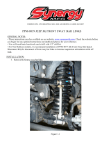
Step 7- Front Sway Bar End Link/Disconnect Installation:
NOTE: This kit contains all parts necessary to install sway bar disconnects / sway bar links on
a Jeep JK Wrangler. For Jeep Rubicon models with the factory electronic sway bar dis-
connect, it is optional to install the kit as fixed links or as an optional method of discon-
necting the front sway bar.
A. Unbolt and remove the front sway bar end links from the vehicle.
B. Locate the new Rubicon sway bar axle mount tab (RM20815 Drvr and RM20816 Pass) to the inside of the OE
sway bar end link mount welded to the axle tube. Attach using the supplied 1/2” X 1 1/2” bolt and hardware.
Torque to 75 ft./lbs. (photo 12)
C. Install the steel pin (RM11140) through the upper hole of the relocation bracket using the supplied 12mm X
35mm bolt, flat and lock washers. Tighten to 50 ft./lbs. (photo 13)
Photo # 12 Photo # 13
Photo # 14
D. Assemble the end link (RM11175), jam nut (HW3037) and 1/2” female rod end (QA1CFR8). Using the supplied
1/2” X 2 1/2” bolt and hardware, secure the rod end to the sway bar inserting the hardware from the inside out.
Be sure to install a misalignment spacer (RM11155) on each side of the rod end. (photo 14)
E. Rotate the end link as shown and secure it to the pin, on the axle, with the supplied retainer pin (HWC12005).
Tighten the jam nut to the rod end while holding the rod end so you do not twist the link. This will allow for eas-
ier removal. (photo 15)

Revised
4.15.14
Photo # 15 Photo # 16
Jeep Rubicon Edition Installation:
NOTE: If using the kit as sway bar links only for the Jeep Rubicon Edition with a factory sway
bar disconnect replace the hardware in step D with the 1/2” X 2 1/2” bolt. Use the
sleeve inside the bushing end of the link and the washer on the outside of the link.
(photo 16)
F. Remove the OE nut from the bottom of the driver and passenger side front body mount and install the end link
stow-away brackets (RM11200). Install the aluminum stow-away pins (RM11205) to the stow-away brackets
using the supplied 1/2” hardware. (photo 17 & 18)
Photo # 17 Photo # 18
Step 8 – Rear Control Arm Bracket Installation:
FUEL TANK REMOVALL: The fuel tank removal should be done when there is less than 1/8 tank of fuel in
the tank to avoid excess fuel sloshing weight Special tools are not required for the removal of the fuel
tank. All plastic clips should come apart by squeezing the outer portion of the clip and gently pulling
apart. The following connections need to be removed: supply and return at the front of the tank, large
plastic line at the charcoal canister, vent hose at fuel tank, and the fuel filler hose. DO NOT use excessive
force, damage to the fittings or seals may result. Before lowering the tank back out the bolt from the right
rear lower control arm to avoid dragging the side of the tank on the end of the bolt. Do not completely
remove the bolt at this time.

Revised
4.15.14
Caution: With the fuel tank removed, there may be fuel vapors present. Use good judgment when drilling, cutting, and
welding near the fuel system components.
A. On the passenger side, with the axle supported, remove the passenger side upper and lower control arms from
the vehicle.
NOTE: Be sure to leave the driver side control arms in place to keep the rear axle from rolling
over
B. Using a suitable cutting tool, (abrasive cutoff wheel, Sawz-all, etc.) cut off the lower control arm mounting pock-
ets from the frame. After trimming the lower control arm mounting pocket, sand the cut area smooth. Clean the
area thoroughly and paint the exposed metal with quality paint. (Photo 19)
IMPORTANT!: DO NOT cut into the frame rail. This will weaken the frame structure considerably.
NOTE: For maximum travel, it may be necessary to trim 1” off the rear body mounts.
C. Raise the pass side rear lower control arm mount bracket (86-RM24138 pass) into place and secure to the frame
using the previously removed OE fuel tank skid plate retaining bolt. Clamp the bracket firmly in place against the
frame.
D. Using the mounting holes in the bracket as a guide, drill the center control arm mounting bolt hole using a 9/16”
drill bit.
E. Drill the upper and front lower holes using a 1/2” drill bit.
F. Secure the bracket to the frame using the 1/2” X 1 1/2” bolt, 9/16” X 4” bolt and the supplied dual nut plate (35-
RM24143). Torque the 1/2” bolt to 80 ft./lbs. Do not tighten the 9/16” bolt at this time.
G. Secure the front lower bracket mounting hole to the frame using the supplied 1/2” X 1 1/2” bolt and nut plate
(35-RM24028).
H. On the driver side the bracket will be located on the frame by measuring 11 1/8” forward from the small square
hole near the rear upper control arm mounting bolt. (Photo 19)
NOTE: The bracket is contoured to fit perfectly against the overlap in the frame.
I. Raise the driver side rear lower control arm mount bracket (86-RM24135 drvr) into place and secure to the frame
using C-clamps.
J. Using the mounting holes in the bracket as a guide, drill the center control arm mounting bolt hole using a 9/16”
drill bit. (Photo 20)
K. Drill the (1) upper and (2) lower holes using a 1/2” drill bit. (Photo 21)
L. Secure the bracket to the frame using the supplied 1/2” X 1 1/2” bolt, 9/16” X 4” bolts and the dual nut plate
(35-RM24143). Torque the 1/2” bolt to 80 ft./lbs. Do not tighten the 9/16” bolt at this time. (Photo 20 & 21)
M. Secure the (2) lower bracket mounting holes to the frame using the (2) supplied 1/2” X 1 1/2” bolts and (2) nut
plate (35-RM24028). (Photo 22)

Revised
4.15.14
Photo # 19 Photo # 20
Photo # 21 Photo # 22
Step 9 – Upper and Lower Control Rear Arm Installation:
A. Prepare the rear of the vehicle for control arm and component installation by removing the following items:
shocks, sway bar links, coil springs, track bar, brake line brackets at the frame, e-brake cables at the axle.
B. Preset the 4-link lower control arms (88-RM31015) to 36.25” center to center and install the coupler end into the
4-link rear frame bracket (86-RM24135 drvr and 86-RM24138 pass) using the supplied 9/16” X 4” bolt hardware.
(Photo 23)
C. Attach the rubber bushing end of the lower arm to the lower control arm mount on the axle housing using the
OE bolt and hardware. DO NOT tighten the rubber bushing until the vehicle is on the ground to avoid bushing
preload.
D. Preset the 4-link upper control arm (88-RM31123) to an initial setting of 18.625” center to center, install the
coupler end into the OE upper arm mounting pocket at the frame using the previously removed OE bolt and
hardware. Be sure there is at least 1” of thread engagement. (Photo 24)
E. Attach the rubber bushing end of the upper arm to the upper mount on the axle using the previously removed
OE bolt and hardware. DO NOT tighten the rubber bushing until the vehicle is on the ground to avoid bushing
preload.
F. Repeat steps A – E on the opposite side.

Revised
4.15.14
NOTE: The upper and lower arms may need to be to be readjusted +/- .250” after the installa-
tion is complete for proper pinion angle and clearance of other components. It is highly
recommended that the OE rockers and body tub are trimmed near the front edge of the
tire to prevent tire damage at full compression. Extending the control arms too far to
allow additional room for the tire can cause too little thread engagement and other
items to contact during suspension travel.
Photo # 23 Photo # 24
Step 10—Rear Brake Line Installation, RE1540:
A. On the driver side, unbolt the brake line bracket from the frame rail. Disconnect the rubber hose from the steel
line at the frame; plug the steel line to prevent excessive fluid loss.
B. Secure the supplied 90 degree brake line mounting bracket to the frame using the previously removed OE bolt.
Position the bracket so it is above the mounting bolt.
NOTE: Left and Right lines are supplied in the kit. Be sure to check that the caliper mounting
block points the hose away from the caliper prior to install. (Photo # 25)
C. Thoroughly clean all mating surfaces of the OE steel brake line and caliper mounting surfaces.
D. Using the supplied copper banjo washers and OE banjo bolt install the brake hose to the caliper. Torque the
banjo bolt to 23 ft./lbs.
E. Insert the new hose assembly thru the previously installed bracket and secure with the supplied spring clip.
F. Carefully thread the OE steel line into the new Stainless Steel brake hose and tighten.
NOTE: DO NOT allow the stainless steel brake hose to twist when tightening to the bracket or
OE brake line. Twists can cause kinks in the brake hose assembly during suspension
travel.
G. Repeat steps A-F on passenger side.

Revised
4.15.14
Photo # 25
Photo # 26 Photo # 27
Step 11—Rear Track Bar Bracket Installation, RE1607:
A. Place the new track bar bracket over the factory track bar mounting point on the axle while aligning the two
3/8” holes on the back side of the lower control arm bracket. Loosely install the two 3/8” bolts, washers, and
nuts through the lower control arm bracket and track bar bracket. (Photo 28)
B. Install the 9/16 X 3 1/2” bolt through the factory track bar location being sure to use the supplied spacer to
keep the factory bracket from collapsing. Tighten the two 3/8” bolts to 35 ft./lbs. then tighten the 9/16” bolt to
90 ft/.lbs. (Photo 28)
C. Install the supplied 9/16 X 3” bolt from the front to back through the bracket and OE track bar. Install locking
nut on bolt but do not tighten at this time. DO NOT tighten until suspension install is complete and vehicle is
sitting on the ground.

Revised
4.15.14
Photo # 28
Step 12 - Rear Bump Stop and Coil Spring Installation:
A. Install the new rear bump stop pad (86-RM22016) to the rear axle OE bump stop pad using the (2) 3/8” X 3/4”
bolts and hardware. (Photo 29)
B. Carefully lower the rear axle to ease in the new coil spring installation. Using the factory isolators install the rear
coil springs into the spring buckets and raise the rear axle into place. Make sure the coil spring seats properly
on the lower spring perch.
NOTE: Be sure to reinstall the factory isolators before raising the springs into place.
Photo # 29

Revised
4.15.14
Step 13— Rear Sway Bar End Link Installation, RE1157:
A. Install the new sway bar end links (35-RM11065) to the sway bar with the supplied 1/2” hardware using the flat
washer to the outside to prevent the bolt head pulling through the eyelet.
B. Install the new sway bar end links (35-RM11065) To the sway bar with the supplied 1/2” hardware using the flat
washer to the outside to prevent the bolt head pulling through the eyelet. (Photo 30)
C. Install sway bar end links to the axle mounting points with the previously removed OE hardware. (Photo 30)
D. Torque the 1/2” hardware to 35 ft./lbs
Photo # 30
Step 14—Rear Shock Installation:
A. Install your new rear shocks into the original mounting positions using the previously removed OE hardware.
Torque the upper mounting hardware to 20 ft./lbs. and the lower to 35 ft./lbs. (Photo 31)
Photo # 31

Revised
4.15.14
Step 15 - Final Details, and Adjustments:
A. Install the front transfer case yoke (RE1810) and front driveshaft (RE1883-365 or RE1883-385- 2012 and up
automatic trans) into the vehicle using the previously removed OE hardware. See enclosed driveshaft and
flange adapter kit instruction manuals for reinstallation.
B. Install the rear driveshaft flange adapter (RE1805) and rear driveshaft (RE1887-430, 4-DOOR OR RE1883-240
2-DOOR) into the vehicle using the previously removed OE hardware. See enclosed driveshaft and flange
adapter kit instruction manuals for reinstallation.
C. On both sides of the vehicle, check the routing of the brake lines and the ABS wire harnesses. There must be
no pinching, rubbing, or stretching of either component. Use zip ties to secure these items. At full droop, cycle
the steering from lock to lock while observing the reaction of these components. Reposition them if needed.
D. Reinstall the rear wheels and lower the vehicle to the ground. Torque the lug nuts according to the wheel
manufacturers recommendations.
E. Position your vehicle on a smooth, flat, hard surface (i.e. concrete or asphalt).
F. Verify all coils are properly seated shocks installed and lower the vehicle.
G. Torque all control arm and track bar rubber bushing hardware. Torque the 9/16” to 130 ft./lbs or manufacturers
specifications where OE bolts are used.
H. Properly bleed brake lines according to the manufacturers assembly manual. Check for leaks and a firm pedal.
I. Make sure the steering wheel is centered and manually disable the factory ESP system before the first test drive.
(Refer to the owners manual for the disable procedure). Drive the vehicle forward and backward a few feet to
be sure that the axle is adjusted properly and the vehicle is tracking in a straight line. Adjust front track bar for
axle center if necessary. Be sure to note the location of steering wheel while driving in a straight line and any
driveline vibrations.
NOTE: Minimum factory caster and maximum factory toe-in seems to work well with these front ends (see
Troubleshooting as well).
J. Adjust upper control arms if necessary for proper front castor angle and rear pinion angle.
NOTE: Below is a diagram of the proper pinion angle for a CV style drive shaft (see Troubleshooting also).
K. Retighten all bolts after 50 miles and again after every off road excursion.
L. After all adjustments have been made, Rubicon Express recommends that your local Jeep dealership “flash” the
computer to adjust for proper tire size and ESP control settings.

Revised
4.15.14
TROUBLESHOOTING
Rear driveline:
Acceleration vibration: Caused by the pinion being too high in relation to the transfer case output shaft. Adjust up-
per control arm to lower pinion accordingly.
Deceleration vibration: Caused by the pinion being too low in relation to the transfer case output shaft. Adjust upper
control arm to raise pinion accordingly.
High speed wobble:
It is a condition where front tires will shimmy after hitting a bump. Avoid bias ply tires and wheels with excessive
offset. Check for worn or loose parts. In most cases a reduction of positive castor will eliminate this condition.

Revised
4.15.14
RUBICON EXPRESS ADVANTAGE LIFETIME WARRANTY
Notice to Owner, Operator, Dealer and Installer:
Vehicles that have been enhanced for off-road performance often have unique handling characteristics
due to the higher center of gravity and larger tires. This vehicle may handle, react and stop differently
than many passenger cars or unmodified vehicles, both on and off–road. You must drive your vehicle
safely! Extreme care should always be taken to prevent vehicle rollover or loss of control, which can
result in serious injury or even death. Always avoid sudden sharp turns or abrupt maneuvers and allow
more time and distance for braking! Rubicon Express reminds you to fasten your seat belts at all times
and reduce speed! We will gladly answer any questions concerning the design, function, maintenance
and correct use of our products.
Please make sure that the Dealer / Installer explains and delivers all warning notices, warranty forms
and instruction sheets included with Rubicon Express product.
Application listings in this catalog have been carefully fit checked for each model and year denoted.
However, Rubicon Express reserves the right to update as necessary, without notice, and will not be
held responsible for misprints, changes or variations made by vehicle manufacturers. Please call when in
question regarding new model year, vehicles not listed by specific body or chassis styles or vehicles not
originally distributed in the USA.
Please note that certain mechanical aspects of any suspension lift product may accelerate ordinary wear
of original equipment components. Further, installation of certain Rubicon Express products may void
the vehicle’s factory warranty as it pertains to certain covered parts; it is the consumer’s responsibility
to check with their local dealer for warranty coverage before installation of the lift.
Warranty and Return Policy:
Rubicon Express warranties its full line of products to be free from defects in workmanship and materi-
als for the life of the product. Rubicon Express’s obligation under this warranty is limited to repair or
replacement, at Rubicon Express’s option, of the defective product. Any and all costs of removal, instal-
lation, freight or incidental or consequential damages are expressly excluded from this warranty. Rubi-
con Express is not responsible for damages and / or warranty of other vehicle parts related or non-
related to the installation of Rubicon Express product. A consumer who makes the decision to modify
his vehicle with aftermarket components of any kind will assume all risk and responsibility for potential
damages incurred as a result of their chosen modifications.
Warranty coverage does not include consumer opinions regarding ride comfort, fitment and design.
Warranty claims can be made directly with Rubicon Express or at any factory authorized Rubicon Ex-
press dealer.
Claims not covered under warranty:
• Parts subject to normal wear; this includes bushings*, shock absorbers, driveshafts, ball joints, tie
rod ends and heim joints.
• Discontinued products at Rubicon Express’s discretion.
• Finish after 90 days.
Rubicon Express accepts no responsibility for any altered product, improper installation, lack of or im-
proper maintenance
or improper use of our products.
*Rubicon Express PT-MEG Super-Ride bushings are covered by the Rubicon Express Advan-
tage Lifetime Warranty,
and will be replaced in the event of failure for the life of the product.
/