Page is loading ...

2562239A
REV. A 506
Printed in U.S.A.
INSTALLATION AND MAINTENANCE INSTRUCTIONS
FOR
53” OHIO STATE HIGHWAY PATROL VISTA® LIGHTBAR (581016-OHPxx)
SAFETY MESSAGE TO INSTALLERS
OF
FEDERAL SIGNAL LIGHT SYSTEMS
People’s lives depend on your safe instal-
lation of our products. It is important to
read, understand and follow all instructions
shipped with the products. In addition, listed
below are some other important safety in-
structions and precautions you should follow:
• To properly install a light assembly: you
must have a good understanding of auto-
motive electrical procedures and systems,
along with proficiency in the installation
and use of safety warning equipment.
• When drilling into a vehicle structure,
be sure that both sides of the surface are
clear of anything that could be damaged.
• A light system is a high current device. In
order for it to function properly, a sepa-
rate ground connection must be made. If
practical, it should be connected to the
negative battery terminal. At a minimum,
it may be attached to a solid metal body
or chassis part that will provide an ef-
fective ground path as long as the light
system is to be used.
• Locate light system controls so the VE-
HICLE and CONTROLS can be operated
safely under all driving conditions.
• This product contains high intensity LED
devices. To prevent eye damage, DO NOT
stare into the light beam at close range.
• You should frequently inspect the light
system to ensure that it is operating
properly and that it is securely attached
to the vehicle.
• File these instructions in a safe place and
refer to them when maintaining and/or
reinstalling the product.
Failure to follow all safety precautions and
instructions may result in property damage, serious
injury, or death to you or others.
I. UNPACKING.
After unpacking the Vista lightbar, inspect it for dam-
age that may have occurred in transit. If the unit has been
damaged, file a claim immediately with the carrier, stating
the extent of damage. Carefully check all envelopes, ship-
ping labels and tags before removing or destroying them.
II. INSTALLATION.
A. General.
The lightbar is completely wired at the factory
and does not require any additional internal wiring. All the
conductors necessary for control of any and all basic and
optional functions are contained in the cable.
The basic light functions of the unit must be
controlled by a user-supplied control head.
Before proceeding, ensure that the lightbar has
been installed on the vehicle roof in accordance with the
instructions packed with the mounting kit.
Light system controls must be located so that
VEHICLE and CONTROLS can be operated
safely under all driving conditions.
1. Route the control cable into the vehicle and
under the dash, near the eventual location of the user-sup-
plied control head.
2. For proper light operation, the control
cable must be properly terminated inside the user-supplied
control head. Using figure 1 and table 1 as a guide, make
the appropriate electrical connections. Ensure that the
lines are adequately fused as shown, and that switch capac-
ity is adequate for the current requirement.
Reverse polarity may damage the power supply
and prevent operation. Ensure that correct polarity
is observed.
3. Connect the separate 8 gauge black lead to
the vehicle battery ground (-) terminal.
NOTE
All of the lightbar functions can be activated by ap-
plying 12VDC to the appropriate control line. The
heavy black lead (-) must be connected to battery
ground, to perform a function check.

CUSTOMER SUPPLIED SUPPLIED WITH LIGHTBAR
1A
1A
1A
1A
1A
1A
WIRES TERMINATE TO STROBE
POWER SUPPLIE(S)
BLK/WHT/RED
BLU/WHT/RED
GRY/WHT/RED
PNK/WHT/RED
VIO/WHT/RED
YEL/WHT/REDHIGH PRIORITY, STRB PWR SPLY
MEDIUM PRIORITY, STRB PWR SPLY
LOW PRIORITY, STRB PWR SPLY
LOW POWER, STRB PWR SPLY
STRB PWR SPLY PAT. SELECTION
STRB HEAD SELECT
(-) TO GROUND
(+) BATTERY
INCOMING POWER CABLE
WHT/VIO
VIO
BLU
YEL
GRY
ORG
GRN
WHT/RED
RED
BACK-UP LOWER LEVEL FLASHERS
REAR HIGH SIDE FLASHER
FRONT HIGH SIDE FLASHER
TAKEDOWN
MAN DOWN
LEFT ALLEY
RIGHT ALLEY
STRB PWR REAR
STRB PWR FRONT
10A
5A
5A
15A
3A
8A
8A
15A
15A
WHT/GRNFA/FT
15A
RED
BLK
EXTERNAL WIRING
INTERNAL WIRING
GND
GND
GROUND SCREW
ON EXTRUSION
BLK
WIRING DIAGRAM
(REFER TO NOTE 1)
FROM SEPARATE
SIGNALMASTER CABLE
EXTERNAL
POWER CABLE
WIRE COLOR
290A5489
NOTE 1. VARIATIONS TO WIRING DIAGRAMS MAY OCCUR WITH SOME OPTION COMBINATIONS. BEFORE CUTTING ANY POWER
CABLE LEADS, PERFORM A FUNCTION CHECK BY APPLYING 12VDC TO THE APPROPRIATE CONTROL LEADS. THE
HEAVY BLACK LEAD (-) MUST BE CONNECTED TO BATTERY GROUND, TO PERFORM A FUNCTION CHECK.
Figure 1.
-2-

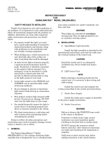
B. Antenna Bracket Installation.
The following is applicable to lightbars that
require an antenna bracket. Before installing the lightbar
on vehicle, the antenna bracket must be mounted to the
underside of lightbar.
See figure 2 and proceed as follows:
NOTE
When turning the lightbar over, use caution to
avoid damaging the lightbar domes.
1. Remove and retain the supplied nut and lock-
washer from the underside of the lightbar.
2. Position the bolt in the center of the lightbar.
Ensure that the area indicated is free from oil and dirt.
3. Remove the liner from the double stick tape
(affixed to the bracket) and mount the bracket to the light-
bar.
4. Using the previously removed hardware,
secure the bracket to the lightbar. Refer to the instructions
included with the antenna for proper installation.
REMOVE
AND
REUSE
PULL AWAY
LINER TAPE
AREA TO BE FREE
OF DIRT AND OIL
FRONT
OF
LIGHTBAR
290A5490
Figure 2.
Table 1. Electrical Connections.
BLK Ground (-)
RED Strobe Power, Front
WHT/RED Strobe Power, Rear
WHT/ORG N.C.
BLK/WHT/RED Strobe Head Select
BLU/WHT/RED Strobe Pattern Select
GRY/WHT/RED Strobe Low Power
PNK/WHT/RED Strobe Low Priority
VIO/WHT/RED Strobe Medium Priority
YEL/WHT/RED Strobe High Priority
VIO Rear Flashing LED
WHT/VIO Back-up Lower Level LED Flasher
WHT/GRY N.C.
BLU Front Flashing LED
YEL Takedown
GRY Man Down
GRN Passenger Alley
ORG Driver Alley
BRN N.C.
WHT/BRN N.C.
WHT/GRN Flashing Alley/Takedown
GRN/WHT/RED N.C.
BRN/WHT/RED N.C.
WHT/BLU N.C.
WHT/YEL N.C.
ORG/WHT/RED N.C.
Wire Color Vista Ricochet Powered Lightbar Function
with Man Down
C. Function Activation.
NOTE
In the four and six head model only one strobe
power supply is provided. The red 12 AWG wire
in the control cable must be connected to 12 VDC
and fused (15-amperes) at the source for the power
supply to operate. In the eight, ten, and twelve
head models there are two strobe power supplies
provided. The red 12 AWG wire (front) and the 12
AWG white/red 12 AWG wire in the control cable
must be connected to 12 VDC and fused (15 AMP)
at the source for both power supplies to operate.
1. Low Priority Control Input.
Applying 12 VDC to the pink/white/red 22
AWG wire in the control cable will select the low priority
mode. This mode will be overridden when the medium or
high priority is selected. This input must be fused (1-am-
pere) at the source.
2. Medium Priority Control Input.
Applying 12 VDC to the violet/white/red 22
AWG wire in the control cable will select the medium
priority mode. This mode will be overridden when the high
priority mode is selected. This input must be fused (1-am-
pere) at the source.
3. High Priority Control Input.
Applying 12 VDC to the yellow/white/red 22
AWG wire in the control cable will select the high priority
-3-

mode. This mode will override both the medium and low
priority modes. This input must be fused (1-ampere) at the
source.
4. Low Power Input
Applying 12 VDC to the grey/white/red 22
AWG wire in the control cable will cause the strobes to
flash at approximately one half power. This input must be
fused (1-ampere) at the source.
NOTE
For eight, ten and twelve head models front or rear
cutoff can be implemented by removing 12 VDC
from the 12 AWG red (front) or 12 AWG white/red
(rear) wires.
D. Programming.
1. Flash Pattern.
The flash pattern assigned to a priority control
input can be change by applying 12 VDC to the desired
priority input, then applying 12 VDC to the blue/white/red
wire will advance the pattern to the next available pattern.
To advance the pattern selection, 12 VDC must be removed
from the blue/white/red wire and re-applied. Repeat the
above until the desired pattern is selected. When 12 VDC is
removed from the priority input, the pattern selection will
be stored in memory. Listed below are the available pat-
terns:
a. Null (no flash)
b. Action
c. ModQuad
d. Sweep
e. Random
f. RicoFlash
g. Triple
h. Triple-2
i. Double
j. Double-2
k. Combo
2. Head Select.
The number of head pairs (A/B, C/D and E/F)
that operate when a priority control input is selected can
be changed by applying 12 VDC to the desired priority
input, then applying 12 VDC to the black/white/red wire
will advance to the next available combination of head pair
operation. To advance to the next available combination,
12 VDC must be removed from the black/white/red wire
and re-applied. When 12 VDC is removed from the priority
input, the head pair combination will be stored in memory.
Listed below are the available head pair combinations:
a. A/B, C/D & E/F
b. A/B & C/D
c. A/B & E/F
d. C/D & EF
e. A/B
f. C/D
g. E/F
E. Function Activation - Lower Level LED’s.
1. Front LED’s/Flasher.
To activate front LED flasher apply 12VDC to the
Blue wire. See figure 1 for proper fusing.
2. Rear LED’s/Flasher.
To activate rear LED flasher apply 12VDC to
the Violet wire. See figure 1 for proper fusing.
3. Backup Operation.
To activate the backup activation for both
front and rear LED flashers apply 12VDC to the WHT/VIO
wire. See figure 1 for proper fusing.
F. Function Activation – Man Down Blue LED
Module.
1. Activation.
Apply 12VDC to the Gray wire. See figure 1
for proper fusing.
2. Intensity Adjustment.
Remove upper center dome. Apply 12VDC
to the Gray wire. Locate the Man Down/Backup Feed cir-
cuit board. Adjust potentiometer R1 clockwise to increase
intensity and counter-clockwise to decrease intensity.
Remove 12VDC and reinstall center dome.
III. BASIC MAINTENANCE.
High voltages are present inside the lightbar.
Wait at least ten (10) minutes, after shutting
off power, before servicing this unit. Failure
to do so may result in property damage, seri-
ous injury, or death to you or others.
Disconnect ALL power to the lightbar before
any maintenance is performed.
A. Cleaning the Plastic Domes.
Ordinary cleaning of the plastic domes can be
accomplished by using mild soap and a soft rag. Should fine
scratches or a haze appear on the domes, they can ordinar-
ily be removed with a non-abrasive, high quality automo-
tive paste wax.
Crazing (cracking) of domes will cause re-
duced effectiveness of light system. Do not
use cleaning agents (which will cause craz-
ing) such as strong detergents, solvents, or
petroleum products. If crazing of domes does
occur, reliability of light for emergency warn-
ing purposes may be reduced until domes are
replaced.
-4-

B. Halogen Lamp Replacement.
A serious injury may result if lamp is touched
when hot. Always allow lamp to cool before
removing. Halogen lamps are pressurized
and if broken can result in flying glass. Al-
ways wear gloves and eye protection when
handling the lamps.
Service life of lamp will be shortened if glass por-
tion is touched. If glass has been handled, clean
carefully with a grease solvent.
For Takedown and Alley Lamps replacement,
see figure 3. Refer to table 2 and replace the defective lamp
with an exact replacement only.
C. Cleaning Reflector Assemblies.
Use a soft tissue to clean the reflectors. Avoid
heavy pressure and the use of caustic or petroleum base
solvents which will scratch or dull the surface.
D. Strobe Tube Replacement.
High voltages are present inside the lightbar.
Wait at least ten (10) minutes, after shutting
off power, before servicing this unit. Failure
to do so may result in property damage, seri-
ous injury, or death to you or others.
Disconnect ALL power to the lightbar before
any maintenance is performed.
As strobe lights are used, flash tubes begin to
darken, causing the light output to decrease. Also, as flash
tubes age, they may have a tendency to misfire (not fire
periodically).
After extended operation, occasionally check
for flash tube degradation. Should the tube misfire, have a
290A5491
BI-PIN, #GH-8, #GH-9
Figure 3.
FUNCTION REPLACEMENT LAMP
Alley, Takedown 50W Halogen, GH-8 (bi-pin)
Part No. 8107169
Primary Strobe Linear Strobe Tube
Part No. 8583302
Man Down LED PCB, LED Assy., 2005145
(blue)
Gen-3 LED Replacement Module
Amber-Part No. 8583228-02
Blue-Part No. 8583228-03
Red-Part No. 8583228-04
Table 2.
noticeable decrease in light output, glow continuously, or
darken excessively, it should be replaced.
NOTE
Not replacing a strobe tube when any of the above
conditions exist could cause a break-down of other
power supply components.
See figure 4 and proceed as follows:
1. Refer to table 2 for the correct strobe tube
part number.
2. Remove and retain the two #8-32 screws
which secure the defective strobe head assembly to the
dome.
3. Disconnect the 3-position red connector
from the wiring harness attached to the dome.
4. Carefully install the new strobe assembly
using the two #8-32 screws. Reconnect the 3-position red
connector to the corresponding connector in the dome.
5. Carefully replace the dome ensuring that
the replaced strobe assembly’s wiring does not interfere
with the operation of other options in the lightbar.
PRIMARY STROBE
ASSEMBLY
290A5492
DOME MOUNT BRACKET
(REMAINS IN PLACE)
#8-32 x 3/8" HEX
HEAD SCREWS
Figure 4.
-5-

E. Strobe Power Supply Fuse Replacement.
High voltages are present inside the lightbar.
Wait at least ten (10) minutes, after shutting
off power, before servicing this unit. Failure
to do so may result in property damage, seri-
ous injury, or death to you or others.
Disconnect ALL power to the lightbar before any
maintenance is performed.
Replace the fuse on the power supply’s top with
an EXACT replacement. The 15A fuse for the primary
strobe power supply is Federal Part No. 148A142-06.
F. Strobe Power Supply Replacement.
High voltages are present inside the lightbar.
Wait at least ten (10) minutes, after shutting
off power, before servicing this unit. Failure
to do so may result in property damage, seri-
ous injury, or death to you or others.
Disconnect ALL power to the lightbar before
any maintenance is performed.
Other than the fuse, the strobe light power sup-
ply does not contain any user serviceable parts. Should a
breakdown in the power supply occur, it should be returned
to Federal for repair and replaced. To remove the power
supply, proceed as follows:
1. Unplug the connectors from the power sup-
ply.
2. Remove the four #8 screws which secure
the power supply.
3. Install the new power supply by perform-
ing the previous steps in reverse order.
290A5493
LED ASSEMBLY
Figure 5.
LED MODULE
290A5494
REMOVE AND
REPLACE SCREWS
Figure 6.
G. LED Assembly Replacement.
A serious injury may result if LED assembly
is touched when hot. Always allow LED as-
sembly to cool before removing.
1. Man Down LED.
See figure 5. Refer to table 2 and replace the
defective LED assembly with an exact replacement only.
2. Gen-3 LED.
See figure 6. Refer to table 2 and replace
the defective LED assembly with an exact replacement
only.
Copyright 2006 Federal Signal Corporation
-6-
/