Page is loading ...

2561595B
REV. B 700
Printed in U.S.A.
INSTRUCTION SHEET
FOR
SIGNALMASTER™ MODEL SMLED6-2DS1
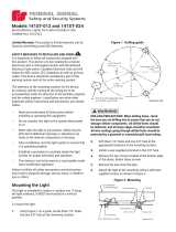
SAFETY MESSAGE TO INSTALLERS
People’s lives depend on your safe installation of
our products. It is important to read, understand and
follow all instructions shipped with the products. In
addition, listed below are some other important
safety instructions and precautions you should
follow:
• To properly install this light: you must
have a good understanding of automotive
electrical procedures and systems, along
with proficiency in the installation and
use of safety warning equipment.
• When drilling into a vehicle structure, be
sure that both sides of the surface are
clear of anything that could be damaged.
• In order for the light to function properly,
a separate ground connection must be
made. If practical, it should be connected
to the negative battery terminal. At a
minimum, it may be attached to a solid
metal body or chassis part that will
provide an effective ground path as long
as the light system is to be used.
• Locate light control so the VEHICLE and
CONTROL can be operated safely under
all driving conditions.
• Do not attempt to activate or deactivate
light control while driving in a hazardous
situation.
• This product contains high intensity LED
devices. To prevent eye damage, DO NOT
stare into the light beam at close range.
• You should frequently inspect the light to
ensure that it is operating properly and
that it is securely attached to the vehicle.
• File these instructions in a safe place and
refer to them when maintaining and/or
reinstalling the product.
Failure to follow all safety precautions and
instructions may result in property damage, serious
injury, or death to you or others.
I. GENERAL.
The Federal SignalMaster™ Model
SMLED6-2DS1 is a low wattage, directional light
assembly that is designed for use in a flashing mode.
Lens colors available are: amber (standard), red,
blue, and clear.
WARNING
These lights are intended for secondary
warning only. They are not intended for use
as a primary warning system.
II. INSTALLATION.
A. SignalMaster Light Assembly.
Install the light assembly as described in the
mounting kit instructions, and route the cable near
the eventual location of the control unit.
CAUTION
Install the control unit in an adequately
ventilated area. Never install near heater
ducts.
B. LED Control Unit.
NOTE
Before selecting a mounting location for the
control unit, it is necessary to plan wiring and
cable routing.
Install the control unit and complete the
wiring as described in the control unit instructions.
C. Strobe Power Supply.
Install the strobe power supply as described
in the power supply instructions.
D. Strobe Connections.
WARNING
Failure to observe this WARNING may result
in fire, burns or blindness.
If shorted to vehicle frame, high current
conductors can cause hazardous sparks
resulting in electrical fires or molten metal.
DO NOT connect this system to vehicle
battery until ALL other electrical connections
are made and mounting of all components is
complete.
Verify that no short circuits exist, before
making connection to the vehicle battery.

1. Disconnect vehicle battery. Ensure that
power is disconnected from all vehicle lighting control
systems.
2. Ensure that the power supply chassis is
grounded to the vehicle chassis. If necessary, connect
a wire from the power supply chassis (mounting
screw) to a known good vehicle chassis ground.
3. See figure 1. Connect the supplied strobe
power supply cables to the power supply. Route the
Model SMLED6-2DS1 cables to the previously
connected strobe power supply cables. Allow for a
drain loop for maintenance, and cut the
SMLED6-2DS1 cables to the proper length.
NOTE
See figure 2. When using a non-Federal
Signal power supply, it may be necessary to
use the other supplied connector and pins.
IMPORTANT
Refer to figures 1 and 3, or 2 and 3, while
completing the electrical connections.
4. See figure 3. Using care to avoid damaging
insulation on the cables’ conductors, remove approxi-
mately 2-inches of each cables’ outer insulation.
Remove approximately 1/4-inch of insulation from
3 2 1
3 2 1
WARNING
HIGH VOLTAGE
SHOCK HAZARD
290A3976
RED -
+ BLK
RED
BLK
RED
BLK
GRN
WHT
WHT
WHT
CONNECT AS
SHOWN
175100 CABLE
SUPPLIED
ELECTRICAL CONNECTIONS
- CAUTION -
REVERSE POLARITY WILL BLOW FUSE
- WARNING -
HIGH VOLTAGE
CONNECTOR
DETAIL
TO SMLED6-2DS1
3 2 1
WHT
RED
BLK
Figure 2.
each conductor. Crimp the four red female connectors
on the ends of each cables’ conductors.
5. Connect the cables’ conductors to the strobe
power supply cables’ conductors by matching the wire
colors as shown in figure 1.
6. Check all connections and wiring. Ensure
that there are no short circuits and that all wires are
protected from any sharp edges. Reconnect the
vehicle battery. Test for proper operation of the strobe
system.
290A3977
TO
STROBE
HEAD
RED
GRN
WHT
BLK
TYPICAL WIRE
OR CABLE ASSEMBLY
EXITING STROBE HEAD.
TERMINATE CABLE ASSEMBLY
(IF NECESSARY WITH RED, Q.D
MALE TERMINALS) (SUPPLIED
WITH KIT, INCLUDED WITH
STROBE HEAD).
WIRE
STRIP
JACKET
STRIP
1/4"
2"
Figure 3.
1 2 3
WARNING
HIGH VOLTAGE
SHOCK HAZARD
1 2 3
290A3975
RED -
+ BLK
RED
BLK
RED
BLK
GRN
WHT
WHT
WHT
CONNECT AS
SHOWN
175100 CABLE
SUPPLIED
ELECTRICAL CONNECTIONS
- CAUTION -
REVERSE POLARITY WILL BLOW FUSE
- WARNING -
HIGH VOLTAGE
1 2 3
RED
BLK
WHT
CONNECTOR
DETAIL
TO SMLED6-2DS1
Figure 1.
-2-

III. MAINTENANCE.
A. General.
WARNING
Crazing (cracking) of lenses will cause re-
duced effectiveness of the light. Do not use
cleaning agents (which will cause crazing)
such as strong detergents, solvents, or petro-
leum products. If crazing of lenses does occur,
reliability of light for emergency signalling
purposes may be reduced until lenses are
replaced.
Ordinary cleaning of the plastic lenses can be
accomplished by using mild soap and a soft rag.
Should fine scratches or a haze appear on a lens, they
can ordinarily be removed with a non-abrasive, high
quality, one-step, automotive paste cleaner/wax and a
soft cloth.
B. LED Module Replacement.
1. See figure 4. Remove and retain the two
screws which secure the LED module assembly.
2. Disconnect the right angle connectors and
remove the LED module assembly.
3. Observing polarity, connect the right
angle connectors to the appropriate printed circuit
board connectors.
4. Install the new LED module assembly
using the previously removed screws.
C. Strobe Tube Replacement.
WARNING
High voltages are present in a strobe light
system. Wait at least five (5) minutes, after
shutting off power, before servicing the unit.
Failure to do so may result in property
damage, serious injury, or death to you and
others.
a. Disconnect all power to the strobe system
power supply before performing any maintenance.
b. Remove and retain the two screws which
secure the lens (see figure 4), and carefully pull the
lens straight away from the light assembly.
c. See figure 5. Remove and retain the
screws which secure the back cover to the mounting
bar.
d. Disconnect the quick connect terminals
from the defective strobe tube.
290A397
8
2
34
1
Figure 4.
e. Remove the strobe tube assembly by
pulling the wires at the base of the strobe tube
assembly. Pull the strobe tube straight away from the
mounting bar.
CAUTION
Service life of strobe tube will be shortened if
glass is touched. If glass has been handled,
clean carefully with a grease solvent.
f. See figure 6. SLOWLY insert the new
strobe tube in the mounting bar until it is properly
seated in the top slot of the strobe tube. If the strobe
tube is difficult to insert, remove it and apply a high
temperature grease, or Vaseline, to the rubber edge of
the strobe tube and try again.
g. Reconnect the quick connect terminals.
Reassemble the unit.
h. Reconnect all power connections to the
power supply and test for proper operation.
290A3979
EXTRUSION
END PLATE
REMOVED
STROBE MOUNTING PLATE
REMOVE STROBE TUBE
ASSEMBLY FROM REAR
STROBE ASSEMBLY
THREE(3) TORX SCREWS
REMOVED
Figure 5.
-3-

290A3980
STROBE TUBE ASSEMBLY
W/TERMINALS
STROBE
MOUNTING PLATE
(REAR FACE)
LUBRICATE STROBE TUBE
ASSEMBLY IN THIS AREA,
TO FACILITATE ASSEMBLY.
SLOWLY
INSERT STROBE TUBE
Figure 6.
SAFETY MESSAGE TO OPERATORS
Peoples’ lives depend on your safe use of our
products.
Listed below are some important safety instruc-
tions and precautions you should follow:
• Although your warning system is operat-
ing properly, it may not be completely
effective. People may not see or heed your
warning signal. You must recognize this
fact and continue driving cautiously.
• Also, situations may occur which obstruct
your warning signal when natural or
man-made objects are between your
vehicle and others, such as: raising your
hood or trunk lid. If these situations
occur, be especially careful.
• This product contains high intensity LED
devices. To prevent eye damage, DO NOT
stare into the light beam at close range.
• At the start of your shift, you should
ensure that the light is securely attached
and operating properly.
Failure to follow these safety precautions may
result in property damage, serious injury, or death to
you, to passengers, or to others.
RETAIN AND REFER TO THIS MESSAGE
D. Replacement Parts List.
Description Part No.
Lens, Clear 8573001
Lens, Red 8573001-01
Lens, Amber 8573001-02
Lens, Blue 8573001-03
Lens, Green 8573001-04
Cable Assembly, 18-ft. 175788
Cable Assembly, Power, Strobe 1751000
LED Module Assy, White, 12V 8573229
LED Module Assy, Red, 12V 8573229-04
LED Module Assy, Amber, 12V 8573229-05
LED Module Assy, Blue, 12V 8573229-06
LED Module Assy, White, 24V 8573229-07
LED Module Assy, Red, 24V 8573229-08
LED Module Assy, Amber, 24V 8573229-09
LED Module Assy, Blue, 24V 8573229-10
Grommet, Split 228116
Strobe Tube Assy. 8575013
Reflector, Strobe 8573187
-4-
1/4