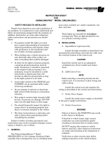
Federal Signal Corporation SignalMaster Controls User manual

Category
Motor vehicle electronics
Type
User manual

This manual is also suitable for

2561063B
REV. B 1002
Printed in U.S.A.
INSTRUCTION SHEET
FOR
SIGNALMASTER™ MODEL 330132
SAFETY MESSAGE TO INSTALLERS AND USERS
People’s lives depend on your safe installation of our
products. It is important to read, understand and follow all
instructions shipped with the products. In addition, listed
below are some other important safety instructions and
precautions you should follow:
To properly install this light: you must have a
good understanding of automotive electrical
procedures and systems, along with proficiency
in the installation and use of safety warning
equipment.
DO NOT install equipment or route wiring in
the deployment path of an air bag.
When drilling into a vehicle structure, be sure
that both sides of the surface are clear of any-
thing that could be damaged.
In order for the light to function properly, a
good ground connection must be made. At a
minimum, it must be attached to a solid metal
body or chassis part that will provide an effec-
tive ground path as long as the light system is
to be used.
Locate light control so the VEHICLE and
CONTROL can be operated safely under all
driving conditions.
Do not attempt to activate or deactivate light
control while driving in a hazardous situation.
You should frequently inspect the light to en-
sure that it is operating properly and that it is
securely attached to the vehicle.
File these instructions in a safe place and refer
to them when maintaining and/or reinstalling
the product.
Failure to follow all safety precautions and instruc-
tions may result in property damage, serious injury, or
death to you or others.
I. GENERAL.
The Federal SignalMaster™ Model 330132 is an
economical, low profile, solid state, directional light control
that is designed to operate with the Federal Signal six-
lamp directional light assembly. The unit is reversed
polarity protected to avoid damage if the positive and
negative power connections are connected incorrectly.
This model provides three distinctive directional
signals: left arrow, right arrow, and center out. In addition,
an alternating flash pattern produces a warning signal for
use when a directional signal may not be appropriate.
When a directional signal is selected, the lamps are
individually illuminated in a sequential sweeping motion
until all six lamps are illuminated.
II. SPECIFICATIONS.
Input Voltage 11VDC to 16VDC.
Polarity Negative ground only.
Operating Temperature -30° C to +65° C.
Range
Standby Current Zero amperes.
+BAT Fuse 25 amperes.
+IGN/BAT Fuse 1 ampere.
Output Drive 6, 27 watt lamps.
Capability (Total)
Flash Rate:
Directional 35 patterns/min.
Warn 60 patterns/min.
Dimensions:
Height 1-1/2"
Width 6-1/8"
Depth 5"
Shipping Weight 2.0 lbs
III. INSTALLATION.
A. SignalMaster Light Assembly.
Install the light assembly as described in the
instructions packed with the mounting kit. Route the cable
near the eventual location of the control unit.
B. Control Unit.
WARNING
When installing equipment inside air bag equipped
vehicles, the installer MUST ensure that the equip-
ment is installed ONLY in areas recommended by
the vehicle manufacturer.
Failure to observe this warning will reduce the
effectiveness of the air bag, damage the air bag, or
potentially damage or dislodge the equipment,
causing serious injury or death to you or others.
See figure 1. The supplied mounting bracket
allows the control unit to be mounted in a variety of
positions. To install the control unit, proceed as follows:
C. Electrical Connections.
WARNING
Failure to observe this WARNING may result
in fire, burns or blindness.
If shorted to vehicle frame, high current conductors
can cause hazardous sparks resulting in electrical
fires or molten metal.
DO NOT connect this system to vehicle battery until
ALL other electrical connections are made and
mounting of all components is complete.
Verify that no short circuits exist, before connecting
to the Positive (+) battery terminal.
The control unit is supplied with a six-position
connector and a eleven-position terminal block to perform
the electrical installation. User-supplied, 14-gauge red and
black wires are required for the (+) BAT and (-) GND
connections on the six-position connector. User-supplied,
18-gauge red and green wires are required for the (+) BAT/
IGN and CASE GROUND connections on the six-position
connector. Using figure 2 as a guide, complete this portion
of the installation as follows:
1. Power Connections.
CAUTION
To avoid damage and ensure proper operation, the
red and black wires MUST be installed in the six-
position connector as shown in figure 3.
WARNING
Do not connect more than one, 6 or 8 head,
halogen SignalMaster assembly to a
SignalMaster controller or the SignalMaster
outputs of a SmartSiren. Electrical fire or
damage to the controller or siren will result.
Figure 1.
CAUTION
Install the control unit in an adequately ventilated
area. Never install near heater ducts.
NOTE
When selecting a mounting location for the control
unit, it is necessary to keep in mind that the Signal
Master cable is 15-feet long. Plan wiring and cable
routing before installation.
1. Select a mounting location for the control unit
that allows the vehicle and controls to be operated safely at
all times.
2. Use the mounting bracket as a template and
scribe two drill position marks at the selected mounting
location.
CAUTION
Before drilling holes in ANY part of a vehicle, be
sure that both sides of the mounting surface are
clear of parts that could be damaged; such as brake
lines, fuel lines, electrical wiring or other vital parts.
3. Drill two holes at the previously scribed
position marks.
4. Secure the mounting bracket to the mounting
surface with two user-supplied, thread-forming, 1/4-20
screws.
-2-
Figure 2.
Figure 3.
a. Strip 1/4" of insulation off of each wire.
See figure 3. Use small blade screwdriver to depress spring
in connector, insert proper wire and remove screwdriver to
release spring.
b. Connect the red and black 14-gauge wires
to the connector as shown in figure 3.
c. Route the red and black 14-gauge wires
through the firewall and toward the battery. Connect the
black wire to a good frame ground near the battery. In
most vehicles, a wire from the negative terminal of the
battery is routed and attached to the body/frame at the
fender. This is a convenient point to connect the 14-gauge
black wire. Do not connect the red wire to the (+) positive
terminal at this time.
d. Connect the 18-gauge red and green wires
to the connector as shown in figure 3.
IMPORTANT
The 18-gauge red wire’s termination point deter-
mines when the directional signal can be activated.
When the wire is attached to a vehicle fuse that is
powered when the ignition switch is in the run or
start position, the vehicle’s ignition switch must be
in the run or start position to operate the directional
signal. When the wire is attached to the vehicle bat-
tery, the directional signal can be operated at any
time. Note that the unit draws no current when in
the “off” position.
e. Select the desired termination point. As
applicable, route the 18-gauge red wire toward the vehicle
fuse block or through the firewall toward the battery.
Install a user-supplied, 1-ampere, in-line fuse in the 18-
gauge red wire as close to the power source as possible and
terminate as required.
f. Route the 18-gauge green wire to a known
good chassis ground near the control. To provide a good
ground connection, scrape any painted surface to bare
metal and terminate as required.
g. Ensure that positions 5 and 6 of the six-
position connector are not used (see figure 2).
h. Plug the six-position connector into the
mating connector on the control unit, and apply pressure
until it locks into place.
2. SignalMaster Cable Connections.
a. Route the SignalMaster cable towards the
control unit, while being careful not to scrape the wires on
any sharp edges.
b. If necessary, cut the cable to the appropri-
ate length.
c. Connect six 22-gauge wires and 16-gauge
red wire to the terminal block as shown in figure 2.
Positions 1, 8, 9, and 10 are not used. Cut the unused white
and blue wires at the cable's insulating sheath.
D. Inspection and Final Installation.
1. Ensure that there are no loose wire strands or
other bare wires which may cause a short circuit. Also, all
wires must be protected from any sharp edges which could
eventually cut through the insulation.
2. Connect the remaining end of 14-gauge red
wire from the six position connector to the (+) positive
terminal of the battery with an in-line, user-supplied
fuseholder and 25A fuse. Locate the fuse as near the
battery as possible to protect the entire length of wire.
3. Read and understand paragraph IV OPERA-
TION, and test for proper operation of all functions.
4. Secure the mounting bracket to the control
unit with the 1/4-20 hex head, thread forming screws and
1/4" external tooth lock washers (see figure 1).
IV. OPERATION.
SAFETY MESSAGE TO OPERATORS
Peoples’ lives depend on your safe use of our products.
Listed below are some important safety instructions and
precautions you should follow:
Although your warning system is operating
properly, it may not be completely effective.
People may not see or heed your warning signal.
You must recognize this fact and continue
driving cautiously.
Also, situations may occur which obstruct your
warning signal when natural or man-made
objects are between your vehicle and others,
such as: raising your hood or trunk lid. If these
situations occur, be especially careful.
At the start of your shift, you should ensure
that the light is securely attached and all lamps
are operating properly. The LED display on the
control only simulates the operation of the lamps.
If a selected function does not perform properly
or if any of the lamps remain illuminated when
the control is off, disconnect the power connector
from the control unit and contact the nearest
service center.
Failure to follow these safety precautions may result in
property damage, serious injury, or death to you, to
passengers, or to others.
RETAIN AND REFER TO THIS MESSAGE
-3-
See figure 4. All controls utilized during normal
operation of the SignalMaster directional light are located
on the front panel of the control unit. The LED display
simulates the light pattern being executed by the direc-
tional light.
A. Slide Switch.
1. LEFT (Position 1).
In this position, the light produces a left arrow
flashing pattern, instructing traffic to move left.
2. CENTER OUT (Position 2).
In this position, a center out flashing pattern
is produced, instructing traffic to move around either side
of the vehicle.
3. RIGHT (Position 3).
In this position, the light produces a right
arrow flashing pattern, instructing traffic to move right.
B. WARN switch.
When this switch is pressed, an alternating
pattern is produced. The two middle lights activate
alternately with the two outside lights on each side. This
pattern will override any of the slide switch functions.
V. SERVICE.
A. General.
Servicing, other than cosmetic features, should be
performed by a qualified Federal Signal service center. If
the control unit is not working properly, disconnect all
electrical connections starting with the six-position power
connector. Remove the control unit from the mounting
bracket. Send the unit to the nearest authorized service
center or the Federal Signal service department.
Communication and shipments should be addressed to:
Service Department
Federal Signal Corporation
2645 Federal Signal Drive
University Park, IL 60466
1-800-433-9132
After servicing is complete, perform a test of all
functions to ensure the control unit is operating properly.
B. Replacement Parts List.
Description Part Number
Printed Circuit Board Assembly 2001135
Knob, Pushbutton 8573065
Knob, Slide Switch 8536C1041
Bezel, Slide Switch 8573060
Connector, Female, 6-Position 140325-04
Bracket, Mounting 8573070
Screw, Hex Head, Mounting 7011164B-08
Lockwasher, 1/4" 7075078
Chassis 8573068
Cover 8573066
Microprocessor SM1CB100
-4-
Figure 4.
  • Page 1 1
  • Page 2 2
  • Page 3 3
  • Page 4 4

Federal Signal Corporation SignalMaster Controls User manual

Category
Motor vehicle electronics
Type
User manual
This manual is also suitable for

Ask a question and I''ll find the answer in the document

Finding information in a document is now easier with AI