Page is loading ...

CPS SCA Series Grid-tied PV Inverter
SCA25KTL-DO-R/US-480
Installation and Operation Manual - Rev 2.1
CHINT POWER SYSTEMS AMERICA CO.
Revision 2.1 - May 2020


Revision History
Rev Number
Chap/Sec
Rev Date
Description
2.0
N/A
Mar 2020
Initial Release

Table of Contents
BEFORE YOU START… ....................................................................... 1
1. IMPORTANT SAFETY INSTRUCTIONS ........................................ 3
2. OVERVIEW ....................................................................................... 8
2.1 INVERTER FOR GRID-TIED PV SYSTEMS ....................................................... 8
2.2 PRODUCT FEATURES .............................................................................. 8
2.3 PRODUCT PROTECTION FUNCTIONS .......................................................... 9
2.4 APPEARANCE AND MAIN ITEM DESCRIPTION ............................................ 10
2.5 SCHEMATIC DIAGRAM AND CIRCUIT DESIGN ............................................. 11
2.6 ANTI-ISLANDING DETECTION ................................................................. 11
2.7 DC GROUND FAULT PROTECTION ........................................................... 12
2.8 SURGE SUPPRESSION ........................................................................... 12
2.9 DC ARC-FAULT PROTECTION .................................................................. 12
3. INSTALLATION .............................................................................. 13
3.1 RECOMMENDATIONS BEFORE INSTALLATION.............................................. 14
3.2 MECHANICAL INSTALLATION .................................................................. 17
3.2.1 Dimensions .......................................................................... 17
3.2.2 Installation Method (see Figure 3-2) ................................... 17
3.2.3 Installation Space Requirement .......................................... 19
3.2.4 Mounting the Inverter onto the Bracket ............................. 20
3.3 ELECTRICAL INSTALLATION ..................................................................... 26
3.3.1 Removing/Replacing the Wire-box Cover ........................... 26
3.4 WIRE-BOX ......................................................................................... 28

3.4.1 DC Connection ..................................................................... 29
3.4.2 AC and Ground Connection ................................................. 36
3.5 COMMUNICATION CONNECTION ............................................................. 41
3.5.1 Description of the Communication Board ........................... 42
3.5.2 RS485 Communication ........................................................ 43
3.5.3 RS485 Network Set-up ......................................................... 44
3.5.4 Communication Wiring ........................................................ 45
4. COMMISSIONING (VIA WIRELESS APP) .................................. 46
4.1 APP DOWNLOAD ................................................................................ 46
4.2 COMMISSIONING CHECKLIST .................................................................. 46
4.2.1 Mechanical Installation ........................................................ 46
4.2.2 Conductor Connections ....................................................... 46
4.2.3 Electrical Check .................................................................... 47
4.3 COMMISSIONING STEPS ........................................................................ 47
4.4 CONNECTION TO THE INVERTER – WIRELESS ............................................. 47
5. APP INTERFACE ........................................................................... 52
5.1 OVERVIEW ......................................................................................... 52
5.2 MAIN SECTION ................................................................................... 52
5.3 RUNNING DATA ................................................................................... 54
5.4 SETTINGS ........................................................................................... 55
5.4.1 Inverter Parameters .................................................................. 56
5.4.2 Read/Write Register .................................................................. 57
5.4.3 Commands ................................................................................ 58
5.4.4 Enable/Disable .......................................................................... 60
5.4.5 Protect ...................................................................................... 67
5.4.6 LVRT/HVRT ................................................................................ 73
5.4.7 ActivePowerDerating ................................................................ 77

5.4.8 ReactivePowerDerating ............................................................ 81
5.4.9 Others ....................................................................................... 87
5.5 FAULT RECORDING ............................................................................... 90
5.6 HISTORY ............................................................................................ 90
5.7 TURN ON/OFF .................................................................................... 91
6. FAULT SHUTDOWN AND TROUBLESHOOTING ...................... 93
6.1 LED FAULT AND TROUBLESHOOTING ......................................................... 93
6.2 FAULT AND TROUBLESHOOTING .............................................................. 94
7. MAINTENANCE AND DE-INSTALLATION ................................ 105
7.1 PRODUCT MAINTENANCE ................................................................... 105
7.1.1 Check Electrical Connections .................................................. 105
7.1.2 Clean the Air Vent Grate ......................................................... 105
7.1.3 Replace the Cooling Fans ........................................................ 106
7.1.4 Replace the Inverter ............................................................... 107
7.2 DE-INSTALLING THE INVERTER .............................................................. 109
8. ACCESSORIES ............................................................................ 111
8.1 SHADE COVER (SSC-25ST-2) ............................................................. 111
8.1.1 Protection from Harsh Conditions .......................................... 111
8.1.2 Increased Energy Production .................................................. 111
8.2 Y-COMB TERMINAL BLOCK (OPTIONAL) ................................................ 112
9. TECHNICAL DATA ....................................................................... 112
9.1 DATASHEET ...................................................................................... 112
9.2 MEASUREMENT TOLERANCES .............................................................. 115
9.3 PRODUCTION GRAPHS ....................................................................... 116
9.3.1 High Temperature Derating Graph ......................................... 116


1
Before You Start…
Scope
This Installation and Operation manual contains important information, safety
guidelines, detailed planning and setup information for installation, as well as
information about configuring, operating and troubleshooting the CPS
SCA25KTL-DO-R/US-480 3-Phase String Inverters. Here after in this manual
this equipment may be referred to simply as the inverters. Be sure to read this
manual carefully before operating or servicing the inverters.
Audience
The information in Chapters 2 “Overview”, 4 “Commissioning (via wireless)", 6
"APP Interface”, and 8 "Accessories" is intended for the owner and operator of
the inverter and does not require any special training or qualifications. The
information in Chapters 3 “Installation”, 4 "Commissioning", 7 “Maintenance
and De-Installation” is intended for qualified personnel only. Qualified
personnel have training, knowledge, and experience in:
▪ Installing electrical equipment and PV power systems (up to 1000VDC).
▪ Applying all local installation codes.
▪ Analyzing and eliminating the hazards involved in performing electrical
work.
▪ Selecting and using Personal Protective Equipment (PPE).
Installation, commissioning, troubleshooting, and maintenance of the inverter
must be done only by qualified personnel.

2
Thank you for choosing a CPS 3-Phase String Inverter. These PV Inverters
are high performance and highly reliable products specifically designed for the
North American Solar market.
Instructions inside this user manual will help you solve most installation and
operation difficulties. Installation, commissioning, troubleshooting, and
maintenance of the inverter must be performed by qualified personnel. If you
encounter any problems during installation or operation of this unit, first check
the user manual before contacting CPS Customer Service. This user manual
is applicable for the following model:
CPS SCA25KTL-DO-R/US-480
Please keep this user manual on hand for quick reference.
The manual will be periodically updated or revised due to the product
development or improvement. The latest version of this manual can be
acquired via the website at www.chintpowersystems.com.

3
1. IMPORTANT SAFETY INSTRUCTIONS
(SAVE THESE INSTRUCTIONS)
Please read this user manual carefully before installation of the inverter. CPS
reserves the right to refuse warranty claims for equipment damage if the user
fails to install the product according to the instructions in this manual.
Warnings and symbols in this document
DANGER:
DANGER indicates a hazardous situation which, if not
avoided, will result in death or serious injury.
WARNING:
WARNING indicates a hazardous situation which, if not
avoided, could result in death or serious injury.
CAUTION:
CAUTION indicates a hazardous situation which, if not
avoided, could result in minor or moderate injury.
NOTICE:
NOTICE indicates a hazardous situation which, if not avoided,
could result in the inverter working abnormally or property
loss.
INSTRUCTION:
INSTRUCTION indicates important supplementary
information or provides skills or tips that can be used to help
you solve a problem or save you time.

4
Markings on the product
CAUTION:
Risk of electric shock from energy stored in
capacitor.
Do not remove cover until 5 minutes after
disconnecting all sources of supply.
CAUTION:
Risk of electric shock, do not remove cover. No
user serviceable parts inside. Refer servicing to
qualified service personnel.
WARNING:
Electric shock hazard. The DC conductors of this
photovoltaic system are ungrounded and may be
energized.
CAUTION:
Risk of Electric Shock.
a) Both AC and DC voltage sources are terminated
inside this equipment. Each circuit must be
individually disconnected before servicing.
b) When the photovoltaic array is exposed to light,
it supplies a DC voltage to this equipment.
WARNING:
Electric Shock Hazard.
The DC conductors of this photovoltaic system are
normally ungrounded but will become intermittently
grounded without indication when the inverter
measures the PV array isolation.

5
CAUTION:
Hot surfaces. To reduce the risk of burns, do not
touch.
WARNING:
For continued protection against risk of fire,
replace only with same type and ratings of fuse.
WARNING:
HAZARDOUS VOLTAGE AREA UNDER THE
PLASTIC COVER.
DO NOT OPEN FUSE HOLDERS UNDER LOAD!
PROTECTIVE GEAR MUST BE USED/WORN
BEFORE ACCESSING FUSES!
WARNING:
High touch current.
Earth connection essential before connecting
supply.
INFORMATION:
For more details please see the user manual.
WARNING:
All the installation and wiring connections must be performed by
qualified technical personnel. Disconnect the inverter from the PV
modules and the AC grid before maintaining or servicing the
equipment.
Failure to follow these instructions and other relevant safety
procedures may result in voiding of the warranty and/or damage to the
inverter or other property!

6
Risk of electric shock and fire. Use only with PV modules that have
a maximum system voltage rating of 1000VDC or higher.
Electric Shock Hazard. The DC conductors of this photovoltaic
system are normally ungrounded but will become intermittently
grounded without indication when the inverter performs the PV array
isolation measurement.
Shock Hazard. The inverter is energized from both AC and DC
sources. Disconnect all energy sources before servicing.
For continued protection against risk of fire, replace only with same
type and ratings of fuse.
DANGER:
Disconnect the inverter from the AC grid and PV modules before
removing covers or opening the equipment. Wait at least 5 minutes
after disconnecting from the DC and AC sources before servicing or
maintaining the inverter. Ensure hazardous high voltage and energy
inside the inverter has been discharged prior to servicing.
NOTICE:
The inverters are designed for PV grid-tied systems. The inverters are
to be installed with floating or ungrounded PV arrays only.
CAUTION:
CPS SCA25KTL-DO-R/US-480 inverters weigh approximately 22kg
(48.5 pounds). The wire-box portion weighs approximately 6kg (13.2
pounds).
Ensure the mounting bracket is properly installed before hanging the
inverter and wire-box on the bracket. A team of two is recommended to
lift and place the inverter and wire-box into position.

7
INSTRUCTION:
Please check with your local electric utility supply company before
selecting a grid standard. If the inverter is operated with an incorrect
grid standard, the electric utility supply company may cancel the
interconnection agreement.
Placing the inverter into operation before the overall system complies
with the national codes, rules and safety regulations of the application
is also not permitted.
WARNING:
This product can expose you to chemicals including lead, known to the
State of California to cause cancer and birth defects or other
reproductive harm. For more information, go to
www.P65Warnings.ca.gov

8
2. Overview
2.1 Inverter for grid-tied PV systems
CPS SCA25KTL-DO-R/US-480 3-Phase Transformerless String Inverters are
designed for use with an ungrounded array in carport, commercial rooftop, and
large utility scale PV grid-tied systems. The system is generally made up of PV
modules, a 3-Phase String Inverter with a fused combiner/disconnect, and AC
power distribution equipment (Figure 2-1). The inverter converts the available
DC energy from the PV modules to AC power by synchronizing the output
current to the same frequency and phase as the AC grid. All or part of the AC
power is supplied to local loads, and the surplus power is exported to the
electric utility grid.
AC Grid
Bidirectional
electric meter
AC power
distribution
equipment
Figure 2-1 Grid-tied PV system
2.2 Product Features
▪ High conversion efficiency: Advanced 3-level conversion topology with
Space-Vector PWM; Max. efficiency: 98.5%, CEC efficiency: 98.0%.
▪ Grid adaptability: IEEE 1547 Interconnect Standard and CPUC Rule 21
applicable; Reactive Power; >0.99 PF (±0.8 adjustable), and optional local
or remote Active Power Curtailment.

9
▪ Flexible communication: Supports standard CPS Modbus RS485,
SunSpec Modbus, and HTTPS/XML communications via Flex Gateway to
ensure compatibility with 3rd party monitoring and control systems. The
Flex Gateway card enables further command/control as well as remote
firmware upgrades. (Flex Gateway card is an optional accessory. Refer to
Flex Gateway manual for further detailed information.)
▪ Wide DC input voltage range: Operating DC Input Voltage Range:
200-950VDC; Max DC input voltage: 1000VDC.
▪ Long Service Life: Designed with thin-film capacitors to extend inverter's
service life.
▪ 2 MPPTs: Multi-channel MPPT (Maximum Power Point Tracker) enables
maximum design flexibility and energy harvest optimization over the life of
the system.
▪ Separable Wire-box: The wire-box enables fused input of industry
standard conductor assemblies.
▪ High protection degree: Powder coated aluminum NEMA 4X enclosure
meets the demanding needs of both indoor and outdoor use.
▪ Intelligent Integration: Integrated load break rated DC/AC disconnect
switches, and up to 6 positive fused string inputs eliminate the need for
external DC combiner boxes, simplifying installation and the need for DC
BOS equipment.
2.3 Product Protection Functions
✓ AC and DC Short circuit protection
✓ Arc-fault detection and circuit interruption
✓ Anti-islanding detection with bi-directional frequency perturbation
✓ DC Input and AC output over-voltage protection
✓ DC Input over-current protection

10
✓ DC input insulation to ground monitoring
✓ DC injection of AC output
✓ AC output voltage and frequency monitoring
✓ Leakage current to ground monitoring
✓ Internal enclosure temperature monitoring
✓ IGBT power module temperature monitoring
✓ RSD function
2.4 Appearance and Main Item Description
1
5
2
3
4
6
7
Figure 2-2 Diagram of the Inverter assembly
Main items of the Inverter:
① Main inverter enclosure
② Inverter wire-box
③ Inverter mounting bracket
④ Cooling fans
⑤ LED indicator lights
⑥ DC switch: DC power on/off
⑦ AC switch: AC power on/off

11
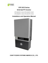
2.5 Schematic Diagram and Circuit Design
The basic electrical schematic diagram of CPS SCA25KTL-DO-R/US-480
inverters are shown in Figure 2-3. The input from PV source circuits passes
through surge protection circuitry, DC EMI wave filters, and independent DC-DC
boost circuitry to achieve maximum power point tracking and boost the voltages
to a common DC bus. The inverter uses line voltage and frequency
measurements to synchronize to the grid and converts the available PV energy
to AC power by injecting balanced 3-phase AC current into the electric utility grid.
Any high frequency AC component is removed by passing through a two-stage
relay and EMI wave filter to produce high quality AC power.
WIRE BOX
INVERTER POWER HEAD
L1
L2
L3
N
PV1+
PV1+
PV1+
PV1-
PV1-
PV1-
MPPT1
MPPT2
AC
Output
PV Input
PV2+
PV2+
PV2+
PV2-
PV2-
PV2-
AC
Switch
Fuses
DC MOV
PV1+
DC Switch
Three
level
inverter
PV2+ PV-
PE
Type Ⅲ MOV
AFD
RSD
Figure 2-3 Schematic Diagram of the CPS SCA25KTL-DO-R/US-480 Inverter
2.6 Anti-islanding Detection
The CPS SCA25KTL-DO-R/US-480 inverters include Unintentional Islanding
detection as required by UL 1741/IEEE 1547. The inverter will continuously
make bi-directional perturbations to the frequency of the output current by
injecting a small amount of reactive power to detect a possible islanding

12
condition. If the grid is stable, these small perturbations will have negligible
effects on the system voltage frequency. However, in an islanded condition the
changes in reactive power will force the frequency of the system voltage to
deviate significantly, which will trigger the inverter to cease operation and
disconnect from the grid.
2.7 DC Ground Fault Protection
The inverters include residual current detection GFCI as part of the DC ground
fault detection method required by UL 1741. If there is a ground fault in the PV
array, the ground fault detection circuitry will detect leakage current, trigger an
alarm, and the inverter will cease operation. See Chapter 5 for further
information regarding GFCI Static and Dynamic trip thresholds and operation.
2.8 Surge Suppression
Table 2-1 Standard Waveform Peak Values
Standard Waveform Peak Values
Surge Category
Ring Wave
Combination Wave
B
6kV/0.5kA
6kV/3kA
▪ "Standard 1.2/50 μs - 8/20 μs Combination Wave"
▪ "Standard 0.5 μs - 100 kHz Ring Wave"
2.9 DC Arc-fault Protection
The inverters include DC Arc-fault detection compliant with UL 1699B-2018.
The inverter will detect electrical noise that is indicative of a DC series arc.
Upon detection of an arc-fault, the inverter will cease operation.
/