Page is loading ...

4215-132 Rev 2 TyloHelo Inc. Page 1
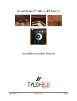
SaunaChrome™ White LED Strip Lighting Using
SaunaChrome Control or Switched 115vac
Power from your Sauna Control
Installation and User Manual
Pages 2-11: SaunaChrome Control
Pages 12-13: Switched 115vac
Pages 14-16: LED Strip Valance Build and Installation
Pages 17-20: Quick Install Guides

4215-132 Rev 2 TyloHelo Inc. Page 2
SaunaChrome™ White LED Control Kit Installation
Carefully unpack and inspect your kit to verify the correct components are included. Verify that the serial number
on the back of your control matches the one located on page 10 of this manual. The base White kit comes with a
“single color” LED touch control and a flush-mount box for recessing the control into your wall. This kit will give
you full-function control of your white LED lighting. Designed to be used exclusively with our 8 and 60w 12vdc
power supplies, 10cm LED light strips, Recessed Ceiling Pucks and 1w Mini-spot light, all sold separately.
READ INSTRUCTIONS THOROUGHLY BEFORE ATTEMPTING YOUR INSTALLATION!
Components of Base White Kit:
9227-337 LED Touch Controller with input/output RJ45 connections
8093-065 Recess mounting box
2310-10 RJ45 In-line connectors (qty: 2)
Instruction manual

4215-132 Rev 2 TyloHelo Inc. Page 3
Verify that the serial number in the warranty
section on page 10 of this manual matches the
serial number on the back of your touch control.
Serial number is located on the back of
the touch control as shown at right.
Step 1.
Your touch control should come pre-wired with
2 RJ45 cables for input/output power. If you are
replacing an existing touch control, connect the
12vdc input cable to the terminal block on the
back of the glass touch screen control panel.
The brown wire will connect to the “V-“
position.
The white with orange stripe wire will
connect to the “V+” position.
Note: The screw terminals may need to be
turned counter-clockwise 6-8 turns prior to
inserting the stripped wire.
Step 2.
Attach the 12v LED output cable as shown at
right (if not already done at the factory)
The brown wire will connect to the “L-“
position.
The White with orange stripe wire will
connect to the “L+” position.
Strip about 3/16” insulation from each wire before inserting
into the terminal block.

4215-132 Rev 2 TyloHelo Inc. Page 4
Step 3.
Install Flush mount enclosure to exterior of sauna
wall. The touch control will mount to this box for
a clean, custom installation.
If your project requires a surface-mounted
control (ie; poured concrete or block wall), a
plastic vapor-resistant box and a metal box for
use with conduit are available from TyloHelo.
Vapor Resistant Surface Mount Box: 8093-065
Requires small bead of silicone caulk (not included)
around edge to make vapor resistant.
Metal box for use with conduit: 8093-064
Determine the location for your touch control and mark the
location with a 3” x 3” “box”.
Make sure this area does not lie directly over framing
members or electrical utilities of your sauna wall.
Use a level to ensure the lines are drawn square.
Hint: Take into account door or window trim that may be
added later in your sauna construction. You will want to leave
plenty of room for these.
Remove the wall material from the marked area using a jig
saw.
Verify that no framing members or electrical utilities
are located behind this area BEFORE drilling/cutting!
Drill out the 4 corners first and simply connect the
holes with your jig saw.

4215-132 Rev 2 TyloHelo Inc. Page 5
With wall material removed, pre-fit the flush mount enclosure
to make sure it fits snug and level in the opening.
When satisfied with the fit of the enclosure in the sauna wall,
push the two black tabs outward and pull each forward until
they make contact with the back of the wall surface.

4215-132 Rev 2 TyloHelo Inc. Page 6
Using a screw driver or utility knife, carefully remove the
upper and lower knock-out tabs so the control cables can be
routed outside of the enclosure.
Remove the glass touch panel from the touch control by
carefully inserting a small flat-blade screw driver into the slot
as shown above and use a twisting/prying action to separate
the glass from the control.

4215-132 Rev 2 TyloHelo Inc. Page 7
Step 4:
Mount the touch control to the enclosure.
It is important to have access to the back side of
your touch control in order to easily connect your
power and distribution cables to the control.
Leaving the wall open inside the sauna will allow
for easy wiring. If leaving the wall open is not an
option, you will want to pre-install the CAT5
power and distribution cables at the time of
framing and connect them to the control panel
by inserting them through the back side of the
enclosure before securing the enclosure to the
exterior sauna wall.
CHECK ORIENTATION OF CONTROL BEFORE
SECURING TO YOUR ENCLOSURE!!!
Insert the two CAT5 cable ends into the upper or lower
opening in your enclosure. (upper will allow more cable to be
in the wall)
Hint: Pre-install one RJ45 inline coupler to each cable end
prior to installing in enclosure.
Secure the panel to your enclosure using the two M3.5 x
30mm screws that were included with your kit.
Do not over-tighten the screws! Snug them until the
panel is firmly held in place.
Be sure to orientate the panel with the red LED
located at the upper left corner, as shown above.

4215-132 Rev 2 TyloHelo Inc. Page 8
Snap the glass panel onto the control by aligning the notches
on the bottom of the panel first then pivoting the glass panel
horizontal. Use light pressure to “snap” the glass cover in
place.
Be sure to orientate the glass panel with the small
clear “window” aligned with the red LED on the
control panel. The power icon should also be
correctly orientated with the vertical line in the 12:00
position.
Correctly orientated panel shown above.

4215-132 Rev 2 TyloHelo Inc. Page 9
Step 5:
Making the electrical connections
The 12vdc input cable on your control should be
connected to either our APV-8-12 or APV-60-12
low voltage transformer, included with your
specific light kit.
8-port splitter kit included with optional light kits.
Your optional LED light kit includes one 8-port
splitter with RJ45 connections. You can connect
up to 8 LED light fixtures to your system using
this splitter.
DO NOT CONNECT A HOME AUTOMATION OR
HOME NETWORK SYSTEM TO THIS SPLITTER!!
DO NOT EXCEED THE RATED WATTAGE OF THE
TRANSFORMER YOU ARE USING!!
If the CAT5 cables provided in your kit are not
long enough, you may source any CAT5 cable
with RJ45 ends (Ethernet) as a substitute.
This splitter can be located in any convenient
location such as on top of your sauna or in an
adjacent utility room. Never locate the splitter
inside sauna cabin UNLESS you are enclosing it
inside a water-tight junction box!
Connect the 12vdc “IN” cable from the touch control
to the 12vdc transformer using an RJ45 in-line
connector. (if additional length is needed, use any
standard CAT5 Ethernet cable) The brown and blue
wires from the transformer will need to be connected
to a constant 120vac/15amp power source.
Note: Your 12vdc transformer may differ from that shown in
photos.
Connect the 12vdc “OUT” cable from the touch
control to the male plug on the 8-port splitter via the
RJ45 in-line connectors. Once this is done, any of the
8 open ports on the splitter are “live” and can be
connected to the LED light bulbs, strips or mini-spot
using the shorter (1 & 2 meter cables) provided in
your kit. Any extra cable can be simply rolled up and
secured with a twist-tie.
If only installing one light fixture, you can connect
directly to the fixture with your CAT5 cable and will
not need the 8-port splitter.

4215-132 Rev 2 TyloHelo Inc. Page 10
Step 8.
Using your touch control
The glass touch control is a “capacitive” device
and will only respond to human touch. Do not
use any metal or other foreign objects to try
operating the control. Reference diagram at right
for specific control functions.
Technical Specifications
4ch output, 4A/ch or 16A/4ch
Input voltage: DC5v or DC 12-24v
Max Power: 80W @ 5v or 192W @ 12v
Static Power Consumption: <1W
Warranty
TyloHelo Inc. will warrant any component of the
SaunaChrome™ light system for a period of 1
year from date of purchase when used as
instructed in a sauna environment. Any other
use may void the warranty.
Date of Purchase____________________
Contact TyloHelo Technical Support for warranty
or installation assistance 1-800-363-0251
Place product serial number in this space

4215-132 Rev 2 TyloHelo Inc. Page 11

4215-132 Rev 2 TyloHelo Inc. Page 12
Connecting White LED lights to Switched 115vac Power
Source.
If having the ability to dim your White LED lights is not necessary, you can connect your lights to
operate using your Sauna Heater Control if it has a light switch or you can connect to any
switched 115vac power source as well. A typical application would be to connect your White
Puck, Valance, Backrest, Under Bench lighting or the Mini-Spot (Gimbal) to a switched 115vac
output. The following instructions will illustrate how to connect to either option.
The Sauna Controls listed below are equiped with a built-in light switch. If your heater control
is not listed or you have a heater with built-in controls then you will need to provide a switched
(standard single pole) 115vac/15amp power source.
Trend
Premium/Elite
T1 (requires separate 15a ckt for lights)
Digi (1, 2 & 7) (requires separate 15a ckt for lights)
SC-60, SC-9, SC-Club (requires separate 15a ckt for lights)
All of the controls listed above provide a switched 115vac output with terminal block
connections that may be located inside the heater, inside the control or if in a large comercial
sauna the connections may be inside a contactor box. You will need to consult the owner’s
manual for your particular heater to determine where your switched 115vac is located.
Low Voltage Connections:
All of the lights in the SaunaChrome family utilize a CAT5 wiring platform. With the only
exception being the 2-conductor wiring harness that connects the individual LED strip lights, all
wiring connections are simple plug-n-play with standard CAT5 cables using RJ45 plug ends.
All lighting surfaces (individual light fixtures or continuous run of strip lights) wire to a central
hub with a “home-run” format. In other words, each fixture will have a CAT5 cable running to
the 8-port splitter. This is the exact method used for a LAN Network BUT do not attempt to
connect these lights to a Network or damage to the Network or lights will result!

4215-132 Rev 2 TyloHelo Inc. Page 13
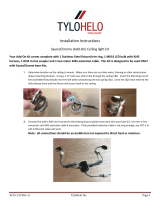
12vdc power for the light system is supplied via either an 8w or 60w power supply that comes
with the lighting system. The following photo shows an example of the 60w power supply but
the 8w supply will wire in the exact same manor. The Blue and Brown wires will connect to
your desired switched power from either the Sauna Heater/Control system or from your single
pole light switch. These power supplies are water proof and can be mounted on the interior of
your sauna. A typical location would be under or near the bottom of your heater or under the
lower bench. While the power supply is water proof, the CAT5 connection is not. So, care must
be taken to ensure this connection is not subjected to direct moisture.

4215-132 Rev 2 TyloHelo Inc. Page 14
How to build & install a simple LED Light Valance Fixture
These steps will work equally well for installing backrest, valance or under-bench LED lights
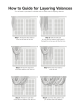
Backside view of a simple valance built from 1x4 cedar with 1x1 stand-off legs.
Each LED strip is attached with two screws and connected electrically with a provided wire
harness. Make sure each connection is fully seated. Apply a slight tug to each to make sure
they will not come apart easily. For best lighting, space each LED strip evenly along the length
of the 1x4 but leave a little slack in the wire harness to allow for expansion/contraction during
the sauna heating process.
Either end of the Valance Light will have open contacts when all LED’s are connected. The
power cable from your 12vdc power supply or from your SaunaChrome Touch Control will
connect to one of these ends. The other end can remain open. Attach completed valance to
sauna wall by drilling/screwing through face of Valance and 1x1 stand off’s.

4215-132 Rev 2 TyloHelo Inc. Page 15
An alternate attachment method is shown below. If you have a large number of LED strips to
install, it may be faster/easier to use a T72 staple gun equipped with 3/8” insulated staples to
attach the LED strips instead of using the small SS screws. Make sure to position the staples in
between the LED diodes to prevent blocking the light or causing shadows. If you do not have
access to a T72 staple gun, regular 3/8” Romex staples will also work for this method.
Mounting the Valance to Sauna wall
In this example, the Valance Light will be mounted on the back wall with the electrical
connections in the left corner. Drill an access hole in the T&G paneling and feed the 2-
conductor end of the special CAT5 cable to the center of where the 1x1 stand-offs will attach to
the wall. You will need at least 6” of the 2-conductor cable to attach to the open connection on
the LED strip. When mounting the valance you can push the extra wire back into the access
hole.

4215-132 Rev 2 TyloHelo Inc. Page 16
Firmly attach the 2-conductor cable to the open end of the LED strip. Give the cable a gentle
tug to make sure the connector is locked onto the LED strip. Push the excess cable back into
the wall cavity and secure the valance to the sauna wall with wood screws.
Attach Valance to wall with wood screws. Hint: mounting the Valance closer to the ceiling will
give you less light wash on the ceiling. The lower you mount it, the more light wash you will
have on the ceiling. You may want to turn the valance on and decide on the best position
before securing to wall. Plug screw holes with wood plugs for a finished appearance.

4215-132 Rev 2 TyloHelo Inc. Page 17
Note: All corner trim should be installed before attaching the Valance Light.

4215-132 Rev 2 TyloHelo Inc. Page 18
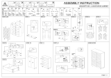
The following “Quick Installation” diagrams on pages 19, 20 & 21 illustrate several
different methods of connecting your lights to either a SaunaChrome Touch
Control or a simple switched 115vac power source, with no dimming capability.
This space is left empty

4215-132 Rev 2 TyloHelo Inc. Page 19

4215-132 Rev 2 TyloHelo Inc. Page 20
/