Page is loading ...

12/18/18
R.D. TF
710-0107 Panel Built Installation
Rev. 03
Page 1
installation instructions
Please immediately check for any hidden damage that
may have occurred in shipping. If any damage is found
you must notify the delivering carrier within seven days.
A few minutes with the following instructions will insure
quick and proper assembly, and many years of enjoy-
ment and relaxation. By reviewing all the instruction
steps ahead of time, you will have a better feel for the
whole process.
Your sauna package will arrive on a stretch-wrapped
pallet including a stack of pre-built panels, benches,
and boxes with the heater and accessories.
Your sauna can be placed on concrete, tile, linoleum,
or any surface that does not absorb water. Do not install
the sauna on carpeting.
•Hammer or pin nailer
•Handsaw and mitre box (for molding installation)
•Drill or cordless screwdriver
•Tape measure
•Square
•Level
•3/8” wood bit (if sauna room has an L-bench)
•Note: Torx bit is provided
modular/panel-built sauna kit
Tools Required
Warning
Drilling, sawing, sanding or machining cedar wood products
can expose you to wood dust, a substance known to the State
of California to cause cancer. Avoid inhaling wood dust or
use a dust mask or other safeguards for personal protection.
For more information go to www.P65Warnings.ca.gov/wood.
Doc # 71-0147

12/18/18
R.D. TF
710-0107 Panel Built Installation
Rev. 03
Page 2
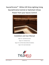
Accessories
Styles may vary based on Interior and Designer Room Series
Trim Proles
Hardware Package
Wood Joiners
Torx Bit
3” Screws
Carriage Bolts
(for saunas with L-benches)
Washers & Nuts
1-1/2” Screws
Cove Molding
Inside 45 Deg. Corner
Molding (on rooms w/
more than 4 walls)
Window/Door Casing
(normally pre-installed)
Outer 45 Deg. Corner
Molding (on rooms w/
more than 4 walls)
Inside Corner Molding
Headrest
Backrest
Door Handle
Vent Grill
Electrical Access Board
Bench
Duckboard
Vent Valve
Note: Half of the groove has been
removed for easy installation
Exterior Facia Trim
(in some models)

12/18/18
R.D. TF
710-0107 Panel Built Installation
Rev. 03
Page 3
1
2
10
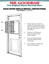
Base Frame Assembly
If the sauna is to be positioned close to a wall or corner, start assem-
bly away from the wall and once the rear panels are istalled push
the sauna into place.
1 Positionthebaseframeontheoor(photoA).Thelargestnum-
ber on the base frame is the standard door location. The stamped
numbers on the base frame should be readable from inside of the
room and correspond to the wall panels that will be placed on them
in a later step.
2 Air inlet has been installed below the heater location.
3 Using one three-inch screw at each corner and the pre-drilled
holes, fasten the corners of the base frame (photo B).
Note: The pre-drilled holes are purposely made at an angle.
4 Using a level and a square, make sure the base frame is square
and level. Shim it where needed with standard shims.
Facia Trim
Ceiling Panel
Top Plate
Interior Cove Molding
Benches
Exterior Corner Trim
Wall Panel
Base Frame
Duckboard Floor
Standard Panel-Built Sauna
Exploded Assembly
A
B
Note: Base rail, top rail and trim are all labeled.

12/18/18
R.D. TF
710-0107 Panel Built Installation
Rev. 03
Page 4
5
4
3 2
3
4
4
4
3
5
5
3
4
2
4
3 2
Exterior
Corner
Trim
Replace
Interior
T&G
3" Torx Screw
Exterior
Corner
Trim
3" Torx Screw
diagram A
Wall Panel Installation
If the sauna is to be placed against existing wall(s), panel installa-
tion should begin at these sides. After these panels are in place,
the sauna can be slid back towards the wall(s) keeping it 1/2” to 1”
away. Note: Vent Valve and Vent Grill are Pre-Installed.
All wall panels are numbered at the top and should be readable
from the interior of the room. These numbers will coincide with the
numbers on the base frame. NOTE: The tongue and groove on the
panels will always face the same direction.
5 Start your wall panel assembly in a corner. NOTE: It is not always
necessary to install your panels in sequence according to their num-
bers. Two wall panels make up each corner. Slide one panel along
thebaseframeuntilits2x2frameworkisushwiththeoutsideofthe
base
frame (diagram A, panel 3).
NOTE: For ease in installing the panels, tilt
the top of each panel back to get the
tongue and groove alignment started . Then tilt for-
wardforaneasyt.
6 Havesomeoneholdtherstpanelinplaceandthenputthe
other corner panel on the base frame and slide it tight into the cor-
ner so its 2x2 framework butts up against the framework of the other
panel (panel 4 from diagram A).
*There are 2 methods for fastening your wall panels ...
Exterior (Standard): To be followed when there is easy access to all
exterior corners of the sauna. See diagram B and follow steps 7A &
8A.
Interior (Alternate): When room was ordered as “Interior Install”. See
Diagram C and follow steps 7B & 8B.
7A Fasten the two panels together from the outside of the room us-
ing 3” torx screws. Holes are pre-drilled.
8A Install exterior, pre-assembled corner trim with provided #4
nishingnails.(photoD).NOTE: One side of the groove has been
removed for easy installation.
7B Fasten the two panels together from the inside of the room using
3” torx screws. Angled holes are pre-drilled.
8B Installtheremovedinteriortongue&grooveusing#4nishing
nails. NOTE: If exterior corner is exposed install exterior, pre-assem-
bled corner trim with provided#4nishingnails.(photoD)
D
D
diagram B
diagram C
or
5
4
3 2
3
4
4
4
3
5
5
3
4
2
4
3 2
Exterior
Corner
Trim
Replace
Interior
T&G
3" Torx Screw
Exterior
Corner
Trim
3" Torx Screw

12/18/18
R.D. TF
710-0107 Panel Built Installation
Rev. 03
Page 5
9 Continue setting the panels into place as marked. Use the barbed
wood fasteners to join the tops of the panels (photo E).
IMPORTANT: If you are in a low ceiling height situation (space above
sauna is less than 3”). You must put the top plate and ceiling panels in
before installing the front wall panels as described in step 10 method B.
NOTE: The door panel should be installed before your last corner panel
is put in place. Use two people to move it as it is quite heavy.
Top Plate Installation
After installing the wall panels, the next step is to assemble and install
the top plate (sometimes referred to as the “ceiling frame”). This top
plate aligns and locks the top of the wall panels together.
There are 2 methods for fastening your top plate ...
Standard: To be followed when there is easy access to the top of the
sauna.
Alternate: To be followed when access to the top of the sauna is lim-
ited.
10a (Standard):
In most installations it is easier to install the top plate one piece at a time,
ratherthanpre-assemblingitontheoor.Todoso,installthesections
onto the front and back wall with the notched ends facing up (photo
F). Then put the side pieces of the plate into place. Firmly press it down
(use a hammer if needed) till it rests on the framework of the wall
panels.Thetopoftheplateshouldbeushwiththetopoftheinterior
tongue and groove. Fasten with one 2” screw in each corner (photo
G).
10b (Alternate): (Especially needed for low ceiling heights)
Layoutallpiecesofyourtopplateontheoor.Usingone1”screwin
each corner, fasten all corners together then drop the top plate into
place along the top of the wall panels. Firmly press it down, using a
hammer if needed, until it rests on the framework of the wall panels.
Thetopoftheplateshouldbeushwiththetopoftheinteriortongue
and groove.
11 Install the provided foam tape along top plate to give a better
seal once the ceiling panels are installed. Tape should be centered on
the top plate and will encircle the entire room.
Ceiling Panel Installation
Low Height Installation Tip: If the clearance above the sauna is less
than 3”, the ceiling panels should be installed prior to the front wall panels.
12 With one person inside the sauna room and another outside, feed
the ceiling panels over the top of the walls being very careful not to
scratch the panels (photo H). When in position, they will rest on the top
plate.
13 In the case of more than one ceiling panel, adjoin the panels as
shown. Lift the panels together, then lower at the same time allowing
the tongue and groove to lock together (photo I).
NOTE: In larger saunas, 3 or more ceiling panels may be provided.
I
front panel removed for photo
H
front panel removed for photo
G
F
press top
plate down
into position
E

12/18/18
R.D. TF
710-0107 Panel Built Installation
Rev. 03
Page 6
Cove Molding Installation
14 The cove molding (3/4” x 1”) will be provided longer than need-
edtoallowtrimmingtoexactsizetoinsureatightt.Measureeach
wall to determine cut length. A simple butt-end cut is the easiest. Cut
molding straight, then butt the pieces together (photo J). If you pre-
fer a mitre joint, the molding is long enough to accommodate that
type of cut as well.
15 Using#4nishingnails(Pneumaticnailerpreferred),nailthecove
molding to the interior walls.
16 Once the molding is secured to the walls nail it through the bot-
tom & into the ceiling to help keep it in place.
Bench Installation
In standard cases, the benches are positioned with the upper bench
against the back wall of the sauna, and the lower bench parallel
to it. There are four bench support boards: two that are 23” long for
the upper bench, and two that are 46” long (length can vary with
sauna model), for the lower bench. This extended length will allow
the lower bench to slide under the top bench for ease in cleaning.
Bench conguration will most likely be different with custom de-
signed rooms.
NOTE: The interior walls have been marked at the heights you should
attach the bench supports, generally top bench support at 30” and
lowerbenchsupportat12”offtheoor.Thesearetheheightsofthe
top edge of the bench supports, not the top of the benches!
17 Position the bench supports about 1/4” away from the back
walls. Making sure they are level, use 3” screws and pre-drilled holes
to secure the bench supports to the walls (photo K ). Be sure to install
screws in all the pre-drilled holes. When installed at the height noted,
the 3” screws will line up with the internal framing of the panels for
necessary strength.
18 Installthebenches,startingwiththebottombenchrst.Note
thatonesideofthebenchisnished,whiletheotherhasexposed
framing. (This may vary with custom designed rooms). The bench
shouldbeinstalledwiththenishedfaceforward.Unlessinstructed
otherwise, the benches do not need to be fastened to the walls. This
will allow for ease in cleaning. However, if you desire no moveability
of benches, fasten the benches directly to the wall using 3” screws
through the 2x4 bench framework (the bench supports should still be
used).
NOTE: Two 3/8” holes have been drilled through the frame of the up-
per L-bench. With the top of the benches aligned, use a 3/8” drill bit
and drill through the 2 provided holes and through the face of the
main upper bench. Bolt the two benches together using the 5-1/2”
carriage bolts provided (photo L). Custom designed rooms may
have a different bench conguration.
Backrest Installation
Some sauna models include backrests. Actual installation height will
vary, depending upon the height of the sauna owner/user. Position
it so the backrest is in the mid-back/shoulder blade area... whatever
feels most comfortable. A standard height is 20” from top of bench
to top of backrest.
J
Bolt
upper L-bench
upper main bench
Underside View
L
M
K

12/18/18
R.D. TF
710-0107 Panel Built Installation
Rev. 03
Page 7
19 Making sure it is level, hold the backrest at your preferred height,
fasten it to the wall through the predrilled holes, using 2” screws (pho-
to M). Wood plugs are provided to cover the exposed screw head.
20 Repeat step 19 if more than one backrest is included. Typically
one backrest for each upper bench is included.
Exterior Facia Installation
NOTE: Do not install the facia until your heater is wired since the elec-
trical access board may need to be removed.
21 The facia can be installed using simple butt-end cuts, or with
mitre cuts. If using butt-end joints, cut the side wall facia the same
length as the side walls (photo N). Fasten with the top edge of the
faciaushwiththetopedgeoftheceilingpanelwithpinnailer.The
frontfaciashouldbecuttooverlapthesidefacia.Installushwith
top of ceiling panel.
Heater Guard Installation
22 Place the heater guard around the heater as described in your
heater instructions. Spacing may vary according to heater kilowatt.
NOTE: The front rails of the 2-sided heater guard can be cut to de-
sired length before assembly.
Interior Light Installation
23 The light should be wired by a licensed electrician according to
local codes. The light can be mounted on a wall of your choice. If
you plan to use the corner lampshade, then the light will need to be
installed tightly into a corner, 4” down from the cove molding (photo
O). Otherwise, off to one side of the door is most common.
Sauna Heater Installation
24 The heater should be wired by a licensed electrician according
to the specications provided with the heater. One of the wall panels
has a removable board to allow for wiring access to the heater (pho-
to P). This tongue and groove board is located in the trim package.
After the wiring is completed, attach the board with the pin nailer.
Door Handle Installation
A pair of door handles is provided with each door. (Styles vary)
Note: If using a wood door for an outside sauna application, it is
recommended to seal the door on all sides including the edges to
prevent condensation damage. (All six sides)
27 Using the screws provided, install the door handles with the cen-
terofthehandleapproximately36”offtheoor,or whatever height
is most comfortable (photo Q). After the handles are fastened, install
theprovidedwoodplugstolltheholes.
Rock Placement (Very Important)
28 Rinse the rocks before placing them in the sauna heater. Place
thesmallerandatterrocksaroundtheoutsideoftherockcompart-
ment and the larger rocks in the center (photo R). This will allow for
good air transfer through the heater. Do not try to force all the rocks
in, It is important to have space between the rocks to give optimum
heater performance, faster heat-up time and higher temperatures.
Save your extra rocks for replacements.
NOTE: facia on front will
overlap facia on side
when using butt joint
front
side
N
O
P
Q
R
large rocks in the middle
smaller/atterrocksinthe
front and back
/