Page is loading ...

Товариство з обмеженою відповідальністю "АЛДІТОП"
Продажа 050-660-22-31
Сервис 050-415-60-94

Товариство з обмеженою відповідальністю "АЛДІТОП"
Продажа 050-660-22-31
Сервис 050-415-60-94
CONTENTS
Product Features and Specifications ..............................................1
Installation Requirement ............................................................ 4
Steps of Installation ………………………………………………..…………………………….5
Exploded View ..........................................................................21
Test Run ..................................................................................26
Operation Instruction ................................................................27
Maintenance ........................................................................... 28
Trouble Shooting ..................................................................... 29
Parts List ................................................................................ 30

Товариство з обмеженою відповідальністю "АЛДІТОП"
Продажа 050-660-22-31
Сервис 050-415-60-94
1
I. PRODUCT FEATURES AND SPECIFICATIONS
FLOORPLATE CHAIN-DRIVE MODEL FEATURES
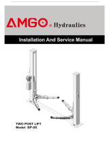
Model 209 (See Fig. 1)
· Compact design
· Dual hydraulic cylinders, designed and made on ANSI standards, utilizing NOK oil
seal in cylinder
· Self- lubricating UHMW Polyethylene sliders and bronze bush
· Single-point safety release, and dual safety design
· Supersymmetric arms design with 3-stages front arms and 2-stages rear arms
. Stackable rubber pad with 1.5” and 2.5” extension adaptors
MODEL 209 SPECIFICATIONS
Model
Style
Lifting
Capacity
Lifting
Time
Lifting Height
Overall
Height
Overall
Width
Width
Between
Columns
Minimum
Pad
Height
Gross
Weight
Motor
209
Floorplate
Chain-drived
4.0T
9,000lbs
45S
1815-1917mm
71 1/2” – 75 1/2”
2742mm
108”
3350mm
132”
2780mm
109 1/2”
90mm
3 1/2”
610Kg
1,345 lbs
2.0/3.0
HP
Fig. 1

Товариство з обмеженою відповідальністю "АЛДІТОП"
Продажа 050-660-22-31
Сервис 050-415-60-94
2
FLOORPLATE CHAIN-DRIVE TWO POST LIFT
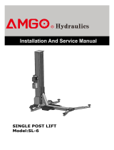
Model 209X (See Fig. 2)
· Compact design
· Dual hydraulic cylinders, designed and made on ANSI standards, utilizing NOK oil seal
in cylinder
· Self- lubricating UHMW Polyethylene sliders and bronze bush
· Single-point safety release, and dual safety design
· Supersymmetric arms design with 3-stages front arms and 2-stages rear arms
. Stackable rubber pad with 1.5”, 2.5” and 5” extension adaptors
MODEL 209X SPECIFICATIONS
Model
Style
Lifting
Capacity
Lifting
Time
Lifting Height
Overall
Height
Overall
Width
Width
Between
Columns
Minimum
Pad Height
Gross
Weight
Motor
209X
Floorplate
Chain-drived
4.0T
9,000lbs
49S
1940-2169mm
76 3/8”–85 3/8”
2841mm
111 3/4”
3460mm
136 1/4”
2850mm
112 1/4”
90mm
3 1/2”
675Kg
1,488 lbs
2.0/3.0
HP
Fig. 2

Товариство з обмеженою відповідальністю "АЛДІТОП"
Продажа 050-660-22-31
Сервис 050-415-60-94
3
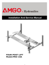
Arm Swings View
For Model 209
Fig. 3
Fig. 4
For Model 209X
1270mm
814mm
683mm
1159mm
893mm
1350mm
722mm
1294mm
2623mm
2513mm

Товариство з обмеженою відповідальністю "АЛДІТОП"
Продажа 050-660-22-31
Сервис 050-415-60-94
4
II. INSTALLATION REQUIREMENT
A. TOOLS REQUIRED
Rotary Hammer Drill (Φ19)
Hammer
Level Bar
English Spanner (12")
Ratchet Spanner With Socket (28
#
)
Wrench set
Carpenter’s Chalk
Screw Sets
Tape Measure (7.5m)
Pliers
Socket Head Wrench (6
#
)
Lock Wrench
(10
#
, 13
#
, 14
#
, 15
#
, 17
#
, 19
#
, 24
#
, 27
#
)
Fig. 5

Товариство з обмеженою відповідальністю "АЛДІТОП"
Продажа 050-660-22-31
Сервис 050-415-60-94
5
B. SPECIFICATIONS OF CONCRETE (See Fig. 6).
Specifications of concrete must be adhered to the specification as following.
Failure to do so may result in lift and/or vehicle falling.
1. Concrete must be thickness 100mm minimum and without reinforcing steel bars,
and must be dried totally before the installation.
2. Concrete must be in good condition and must be of test strength 3,500psi
(210kg/cm²) minimum.
3. Floors must be level and no cracks.
Fig. 6
C. POWER SUPPLY
The electrical source must be 3HP minimum. The source cable size must be 2.5mm²
and in good condition of contacting with floor.
III. STEPS OF INSTALLATION
A. Location of Installation
Check and insure the installation location (concrete, layout, space size etc.) is
suitable for lift installation.
B. Use a carpenter’s chalk line to establish installation layout of baseplate (See Fig. 7-8).
Fig. 7 Model 209
Chalk line
66
Concrete intensity must be
3000psi (210kg/cm²) minimum

Товариство з обмеженою відповідальністю "АЛДІТОП"
Продажа 050-660-22-31
Сервис 050-415-60-94
6
C. Check the parts before assembly.
1. Packaged lift and hydraulic power unit (See Fig. 9).
Fig. 9
2. Move the lift aside with fork lift or hoist, and open the outer packing carefully, take off
the parts from upper and inside the column, take out the parts box, check the parts
according to the shipment parts list(See Fig. 10).
Fig. 10
Shipment Parts list
Floor cover
Parts box
Serial No.
Fig. 8 Model 209X
3460mm

Товариство з обмеженою відповідальністю "АЛДІТОП"
Продажа 050-660-22-31
Сервис 050-415-60-94
7
3. Loosen the screws of the upper package stand, take off the upper column and remove
the package stand.
4. Move aside the parts and check the parts according to the shipment parts list.
4.1 For model 209(See Fig. 11, Fig. 12).
4.2 For model 209X (See Fig. 13, Fig. 14).
Fig. 11
77
77A
Fig. 12
Parts in the parts box(77)
Fig. 14
Parts in the parts box (77A)
Fig. 13

Товариство з обмеженою відповідальністю "АЛДІТОП"
Продажа 050-660-22-31
Сервис 050-415-60-94
8
5. Open the carton of parts and check the parts according to parts box list
(See Fig. 15 & Fig.16).
Model 209
Fig. 15
Model 209X
Fig. 16

Товариство з обмеженою відповідальністю "АЛДІТОП"
Продажа 050-660-22-31
Сервис 050-415-60-94
9
D. Position powerside columns
Lay down two columns on the installation site parallelly, position the powerside
column according to the actual installation site. Usually, it is suggested to install
powerside column on the front-right side from which vehicles are driven to the lift
(See Fig. 17 & Fig. 18).
Fig. 17 Model 209
Fig. 18 Model 209X
Car-in direction
Powerside column
Offside column
Assemble topplate using
M10*35 hex bolt with
nut and lock washer
Car in Direction
Powerside column
Offside column
Assemble topplate using
M10*35 hex bolt with
nut and lock washer

Товариство з обмеженою відповідальністю "АЛДІТОП"
Продажа 050-660-22-31
Сервис 050-415-60-94
10
E. Connecting the cables
1.Put down columns and then push the carriages higher than chain pulley (See Fig. 19).
2.Push the carriages to the bottom of the columns (See Fig. 20).
Fig. 19
Fig. 20
Push the carriages higher than chain
pulley, cable pass through the top of the
carriages and pass through the hole of the
bottom steel plate of the carriages
Pull out cable

Товариство з обмеженою відповідальністю "АЛДІТОП"
Продажа 050-660-22-31
Сервис 050-415-60-94
11
F. Position columns (See Fig. 21)
Check the columns plumbness with level bar, and adjusting with the shims if the
columns are not vertical.
G. Fix anchor bolts
1. Prepare anchor bolts (See Fig. 22).
Fig. 22
2. Using the prescribed rotary hammer drill, and drill all the anchor holes and install the
anchor bolts. Then tighten the anchor bolts (See Fig. 23).
Note: Torque of Anchors is 117N.m .Minimum embedment of Anchors is 90mm.
Fig. 23
Fig. 21
Model 209: 2780 mm
Model 209X: 2850 mm
Model 209: 3350 mm
Model 209X: 3460 mm
Lock washer
Washer
Nut
90mm

Товариство з обмеженою відповідальністю "АЛДІТОП"
Продажа 050-660-22-31
Сервис 050-415-60-94
12
H. Lift the carriages up by hand and make them be locked at the same level
(See Fig. 24).
Fig. 24

Товариство з обмеженою відповідальністю "АЛДІТОП"
Продажа 050-660-22-31
Сервис 050-415-60-94
13
I. Install cable (See Fig. 25)
Fig. 25
The fitting of cable pass through
the hole of the carriages and be
screwed with two cable nuts.

Товариство з обмеженою відповідальністю "АЛДІТОП"
Продажа 050-660-22-31
Сервис 050-415-60-94
14
J. Assembly oil hose assy. (See Fig. 26).
Fig. 26
71
68
71A
71
69A
70
71
69
71

Товариство з обмеженою відповідальністю "АЛДІТОП"
Продажа 050-660-22-31
Сервис 050-415-60-94
15
K. Install hydraulic power unit and oil hose assy. (See Fig. 27).
Tighten all the hydraulic fittings, and fix the oil hose by retainer.
Note: In consideration of Power Unit’s durability and keep the equipment running
in the perfect condition, please use Hydraulic Oil 46#
Fig. 27
Locking the nut using 19#
ratchet spanner
76
75
68
Fix the oil hose by
retainer.
5

Товариство з обмеженою відповідальністю "АЛДІТОП"
Продажа 050-660-22-31
Сервис 050-415-60-94
16
60
Safety cable
connecting
direction
L. Install safety device and safety cable (See Fig. 28).
NOTE: 1. Assemble safety cable from offside safety assy.
2. Pay attention to the connecting direction of safety cable.
Fig. 28
View A
View B

Товариство з обмеженою відповідальністю "АЛДІТОП"
Продажа 050-660-22-31
Сервис 050-415-60-94
17
Protective rubber
sets
Floor Cover
M. Assemble floor cover and protective rubber sets (See Fig. 29).
Fig. 29
N. Install lifting arms and adjust the arm locks
1. Install the lifting arms (See Fig. 30 & Fig. 31)
Model 209
Fig. 30
Model 209X
Fig. 31
Snap Ring
Snap Ring

Товариство з обмеженою відповідальністю "АЛДІТОП"
Продажа 050-660-22-31
Сервис 050-415-60-94
18
2. Lowing the carriages down to the lowest position, then use the 17# ratchet spanner to
loosen the nut (See Fig. 32)
3. Adjust the arm lock as arrow direction (See Fig. 33).
Fig. 33
4. Adjust the moon gear and arm lock to make it to be meshed, then tighten bolts of
arm lock (See Fig. 34).
Fig. 32
Fig. 34
Loosen the nut
Arm lock
Moon Gear
/