Page is loading ...

PX09/PX09A
(X400/X400A)

CONTENTS
Product Features and Specifications ........................................................1
Installation Requirement .......................................................................3
Steps of Installation .............................................................................4
Exploded View ....................................................................................19
Test Run ............................................................................................25
Operation Instruction ..........................................................................26
Maintenance ......................................................................................26
Trouble Shooting ................................................................................28
Parts List ..........................................................................................29

1
I. PRODUCT FEATRUES AND SPECIFICATIONS
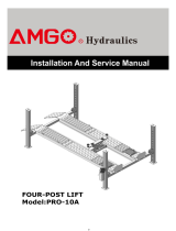
Professional Alignment Scissors Lift
Model PX09A(X400A)
· Electric- air control system, mechanical safety locks
· Dual synchronous cylinders are applied to assure the lifting level on both platforms
· Skid proof diamond platform.
· Integrated rear slip-plates
· Heavy duty design, fit for a wide range of vehicle car to van and light truck.
· Optional Jack (with hand pump/air-operated hydraulic pump)
· Optional Turnplate
Model PX09A(X440A) SPECIFICATIONS
Model
Lifting
Capacity
Lifting
Height
Min.
Height
Lifting
Time
Overall
Length
(Inc. Ramps)
Runway
Length
Overall
Width
Runway
Width
Distance
Between
Platform
Gross
Weight
Motor
PX09A
(X400A)
4.0T
9000 lbs
1870mm
73 5/8”
300mm
11 3/4”
55S
6240mm
245 5/8”
4739mm
186 1/2”
2190mm
86 1/4”
625mm
24 5/8”
855mm
33 5/8”
1938Kg
4,263 lbs
2.0/3.0
HP
Fig. 1

2
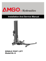
Professional non-alignment Scissors Lift
Model PX09(X400)
· Electric- air control system, mechanical safety locks
· Dual synchronous cylinders are applied to assure the lifting level on both platforms
· Sand resistance platform to avoid skidding
· Heavy duty design, fit for a wide range of vehicle car to van and truck
· Optional Jack (with hand pump/air-operated hydraulic pump)
MODEL PX09 SPECIFICATIONS
Model
Lifting
Capacity
Lifting
Height
Min.
Height
Lifting
Time
Overall
Length
(Inc. Ramps)
Runway
Length
Overall
Width
Runway
Width
Distance
Between
Platform
Gross
Weight
Motor
PX09
(X400)
4.0T
9000 lbs
1870mm
73 5/8”
300mm
11 3/4”
55S
6580mm
259 1/16”
4739mm
186 1/2”
2190mm
86 1/4”
625mm
24 5/8”
855mm
33 5/8”
1720Kg
3,785 lbs
2.0/3.0
HP
Fig. 2

3
II. INSTALLATION REQUIREMENT
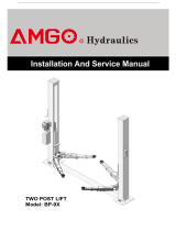
A. TOOLS REQUIRED
Rotary Hammer Drill (Φ19, Φ10, Φ4,)
Hammer
Level Bar
English Spanner (12")
Ratchet Spanner With Socket (28
#
)
Wrench Set
(8
#
, 14
#
, 15
#
, 17
#
, 19
#
)
Carpenter’s Chalk
Screw Sets
Tape Measure (7.5m)
Pliers
Lock Wrench
Grease gun
Fig. 3

4
B.SPECIFICATIONS OF CONCRETE
Specifications of concrete must be adhered to the specification as following.
Failure to do so may result in lift and/or vehicle falling.
1.Concrete must be thickness 100mm minimum and without reinforcing steel bars,
and must be dried totally before the installation.
2 . Concrete must be in good condition and must be of test strength 3,000psi
(210kg/cm²) minimum.
3.Floors must be level and no cracks.
C.POWER SUPPLY
The electrical source must be 2.2Kw minimum. The source cable size must be
2.5mm² and in good condition of contacting with floor.
III. STEPS OF INSTALLATION
A. Location of Installation
Check and insure the installation location (concrete, layout, space size etc.) is
suitable for lift installation.
1. For Standard Installation: On surface installation
1.1 PX09/PX09A(X400/X400A) On surface installation foundation (See Fig. 4).
Fig. 4

5
1.2 Illustration of scissors lift PX09(X400) on surface installation (See Fig.5).
1.3 Illustration of scissors lift PX09A(X400A) on surface installation (See Fig.6).
Fig. 5
Fig. 6

6
2. For Optional Installation: Flush mount installation
2.1 Flush Mount Installation Foundation (Fig.7).
2.2 Illustration of scissors lift PX09(X400) flush mount installation (Fig.8).
Fig. 7
Fig. 8
Power input 4*2.5
2
mm
Air source input
φ50 PVC Tube

7
2.3 Illustration of scissors lift PX09A(X400A) flush mount installation (Fig.9).
B. Check the parts before assembly.
1. Packaged lift and control cabinet (See Fig. 10).
Fig. 10
Fig. 9

8
2. Move aside the lift with fork lift or hoist, and open the outer packing carefully
2.1 Parts for lift of on surface installation (See Fig.11, Fig.12)
For Model PX09A(X400A)
For Model PX09(X400)
Fig. 11
PI
PII
78
PI
PII
79
Fig. 12

9
2.2 Parts for lift of flush mount installation (See Fig.13, Fig.14)
Note: Need guide ramps for flush mount installation
For PX09A(X400A)
Fig. 13
80
81
Guide ramp
(510018)
PI
PII
PI
PII
Guide ramp
(510019)
Fig. 14
For PX09(X400)

10
3. Open the parts box, check the parts according to the part list (See Fig. 15, Fig.16).
4. Check the parts of the parts bag according to the parts bag list.
4.1 Pasts bag for lift of on surface installation (See Fig.17, Fig.18)
For Model PX09A(X400A)
For Model PX09(X400)
Fig. 17
Fig. 18
PX09A(X440A) parts box
Fig. 15
PX09(X440) parts box
Fig. 16

11
4.2 Parts bag for lift of flush mount installation (See Fig.19, Fig.20)
For Model PX09A(X400A)
For Model PX09(X400)
C. Layout the model and install oil system and air line system.
1. Select a location and layout the model according to steps A (See Fig. 21-22).
The control cabinet can be installed on the left or right of the model according to the
site.
PII
PI
Fig. 21
For Model PX09A(X400A)
Fig. 19
Fig. 20

12
2. Connecting the oil hose and air line (See Fig. 23).
Fig. 22
PII
P
I
Fig. 23
For Model PX09(X400)
Connect to the
A of Air solenoid
valve
PI
PII
○
,1Hose 1/4*2240
○
,2Hose 1/4*4860
○
,3Hose 1/4*4860

13
3. Install the oil-water separator (See Fig. 24).
4. Connecting the air source (air pressure 5kg/cm
2
- 8kg/cm
2
), adjust the air pressure
to 0.4- 0.6MPa (See Fig. 25).
Fig. 24
Connect
the air source by the
oil-water separator
64
12-11
12-8
66
62
65
63
Clockwise to increase the air pressure
Counter-clockwise to reduce the air pressure
Adjust the air pressure to 0.4~0.6MPa
Adjust the air
pressure
to
0.4~0.6MPa
Fig. 25
Connecting
air source

14
D. Install electric system
1. Adjusting the current rating of thermal relay in control box according to the different
configurations of hydraulic power unit. In general, the electric current of thermal
relay should equal or larger than that of motor. The following table shows rated
current regulation of thermal relay in case of different hydraulic power unit.
2. Wire connection of hydraulic power unit (380V)
2.1 Connect the power wire and limit switch wire according to the wiring diagram (See
Fig. 27).
Hydraulic power unit 3.0HP/1 phase 3.0HP/3 phase
Rated current of thermal relay
18A 12A
Fig. 26
Ea
rt
h Wire
Power Wire
Hydraulic
solenoid valve
Heigh
Limit switch
Motor Wire
Fig. 27
This point shows
the present rated
current value
Using cross screwdriver
to adjust rated current
value of thermal relay
Low
Limit
switch

15
2.2 Circuit Diagram (See Fig. 28).
Electric Component
3. Wire connection of hydraulic power unit (220V)
3.1 Connect the power wire and limit switch wire according to the wiring diagram (See
Fig. 29)
Item
Name
Code
Specification
Item
Name
Code
Specification
1
Power
s
witch
QS
380V AC
10
Push b
utton
UP
Duplex
2
Fuse
FU
1
25A
11
Push b
utton
LOCK
Duplex
3
Fuse
F
U2
3A
12
Push b
utton
Down1
Triple
4
AC
c
ontactor
KM
24V AC
13
Push button
Down2
Duplex
5
T
hermal relay
FR
12A
-
18A
14
Motor
M
3 Phase
6
Time relay
KT
24V AC
15
Buzzer
H
24VAC
7
Limit Switch
SQ
(
1~2
)
10A
16
Transformer
TC
24V AC
8
Hydraulic
Solenoid Valve
Y1
24V AC
17
Intermediate
relay
KA
24VAC
9
Air solenoid
Valve
Y
2
AC 24V
Fig. 28
Ea
rt
h Wire
Power Wire
Hydraulic
solenoid
v
alve
Low
Limit
switch
Motor Wire
Fig. 29
3 phase
Height
Limit switch

16
3.2 Circuit Diagram (See Fig. 30).
Electric Component
E. Level two platforms and install anchor bolts.
1. Check by level bar and use the shims to adjust the platforms until two platforms are
in the same level (See Fig.31).
Item
Name
Code
Specification
Item
Name
Code
Specification
1
Power
s
witch
QS
38
0V AC
10
Push button
UP
Duplex
2
Fuse
FU
1
25A
11
Push button
LOCK
Duplex
3
Fuse
FU2
3A
12
Push button
Down1
Triple
4
AC
c
ontactor
KM
24V AC
13
Push button
Down2
Duplex
5
T
hermal relay
FR
12A
-
18A
14
Motor
M
Single Phase
6
Time relay
KT
24V AC
15
Buzzer
H
24VAC
7
Limit Switch
SQ
(
1~2
)
10A
16
Transformer
TC
24V AC
8
Hydraulic
solenoid valve
Y1
24V AC
17
Intermediate
relay
KA
24VAC
9
Air solenoid
valve
Y
2
AC 24V
Fig. 30
PII
P
I
Using the Level Bar for
the measurement
Fig. 31
Single phase

17
2. Install anchor bolts.
2.1 Raise the lift to 1000mm then drill holes to install the anchor bolts (See Fig.32).
2.2 Fix the anchor bolts.
Drilling the hole for the anchor bolt with the rotary hammer drill, type the anchor
bolt into the ground, and then fasten it with ratchet spanner (See Fig. 33).
Note: The tightening torque for the anchor bolt is 117N.m. Tap anchor
bolts into the anchor hole at least 90mm deep
Using the anchor bolt
to fix the model
1000mm
Fig. 32
Drilling
Clearing
Bolting
Tighten
47
Fig. 33
P1
P2
69
Using the anchor
bolt to fix the
control cabinet
70
Anchor bolts for the model:Use 19 driller to drill hole
Anchor bolts for the control cabinet:Use 10 driller to
drill hole
90mm

18
F. Install runway connecting bar (See Fig. 34).
G. Install oil hose cover for lift of on surface installation.
1. Tidy up the oil hose and air line, cover the oil hose cover (See Fig. 35).
2. Install the oil hose cover (See Fig. 36).
34
Fig. 34
Using the colloidal
screw to fasten the
oil hose cover
71
P1
P2
Fig. 35
Fig. 36
73
72
Type the expansion
colloidal
screw
Fastening by Install
the steel screw
Cleaning
Drilling with
4 driller
/