PEAK AMGO PX12A Installation and Service Manual

Type
Installation and Service Manual

This manual is also suitable for

PX12/PX12A
(X550/X550A)
CONTENTS
Product Features and Specifications ........................................................1
Installation Requirement .......................................................................3
Steps of Installation .............................................................................4
Exploded View ....................................................................................23
Test Run ............................................................................................28
Operation Instruction ..........................................................................29
Maintenance ......................................................................................30
Trouble Shooting ................................................................................32
Parts List ..........................................................................................33
1
I. PRODUCT FEATRUES AND SPECIFICATIONS
Professional Alignment Scissors Lift
Model PX12A(X550A)
· Electric- air control system, safety self-lock mechanism
· 2-Dual synchronous cylinders are applied to assure the lifting level on both platforms
· Non-skid diamond runway
· Integrated rear slip-plates
· Heavy duty design, fit for a wide range of vehicle car to van and light truck.
· Optional Jack (with hand pump/air-operated hydraulic pump)
· Optional Turnplate
MODEL PX12AX550A SPECIFICATIONS
Model
Lifting
Capacit
y
Lifting
Height
Min.
Height
Lifting
Time
Overall
Length
(Inc.Ramp
s)
Runway
Length
Overall
Width
Runway
Width
Gross
Weight
Motor
PX12A
(X550A)
5.5T
12000
lbs
1870mm
73 5/8”
300mm
11 3/4”
58S
6554mm
258”
5018mm
197 1/2
2290mm
90 1/8”
625mm
24 5/8”
2320Kg
5105
lbs
4.0HP
Fig. 1
2
Professional non-alignment Scissors Lift
Model PX12(X550)
· Electric- air control system, safety self-lock mechanism
· Dual synchronous cylinders are applied to assure the lifting level on both platforms
· Non-skid diamond runway; supper wide platform
· Heavy duty design, fit for a wide range of vehicle car to van and truck
· Optional Jack (with hand pump/air-operated hydraulic pump)
MODEL PX12(X550) SPECIFICATIONS
Model
Lifting
Height
Min.
Height
Lifting
Time
Overall
Length
(Inc.
Ramps)
Overall
Width
Runway
Width
Distance
Between
Baseframe
Gross
Weight
Motor
PX12
(X550)
1870mm
73 5/8”
300mm
11 3/4”
58S
6784mm
267”
2290mm
90 1/8”
625mm
24 5/8”
955mm
37 5/8”
2058Kg
4528
lbs
4.0HP
Fig. 2
3
II
.
INSTALLATION REQUIREMENT
A. TOOLS REQUIRED
Rotary Hammer Drill (Φ19, Φ10, Φ4,)
Hammer
Level Bar
English Spanner (12")
Ratchet Spanner With Socket (28
#
)
Wrench Set
(8
#
, 14
#
, 15
#
, 17
#
, 19
#
)
Carpenter’s Chalk
Screw Sets
Tape Measure (7.5m)
Pliers
Lock Wrench
Grease gun
Fig. 3
31
B
SPECIFICATIONS OF CONCRETE
Specifications of concrete must be adhered to the specification as following.
Failure to do so may result in lift and/or vehicle falling.
1
Concrete must be thickness 100mm minimum and without reinforcing steel bars
and must be dried completely before the installation.
2 Concrete must be in good condition and must be of test strength 3,000psi
(210kg/cm²) minimum.
3Floors must be level and no cracks.
C
POWER SUPPLY
The electrical source must be 3Kw minimum. The source cable size must be 2.5mm²
and in good condition of contacting with floor.
III. STEPS OF INSTALLATION
A. Location of Installation
Check and insure the installation location (concrete, layout, space size etc.) is
suitable for lift installation.
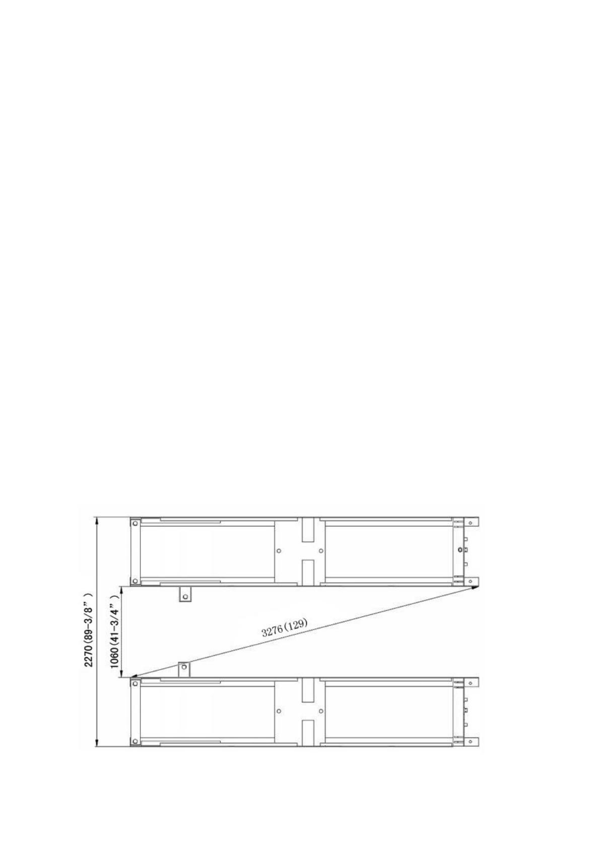
1. For Standard Installation: On surface installation
1.1 PX12/PX12A(X550/X550A) On surface installation foundation (See Fig. 4).
Fig. 4
4
32
1.2 Illustration of scissors lift PX12(X550) on surface installation (See Fig.5).
1.3 Illustration of scissors lift PX12A(X550A) on surface installation (See Fig.6).
Fig. 5
Fig. 6
85
88A
86
88A
86
88A
88
5
33
2. For Optional Installation: Flush mount installation
2.1 Flush mount installation foundation (Fig.7).
2.2 Illustration of scissors lift PX12(X550) with flush mount installation (Fig.8).
Fig. 7
Fig. 8
Power input 4*2.5
2
mm
Hydraulic system, limit
switch , Air source input
φ50 PVC Tube
6
34
2.3 Illustration of scissors lift PX12A(X550A)with flush mount installation (Fig.9).
B. Check the parts before assembly.
1. Packaged lift and control cabinet (See Fig. 10).
Fig. 10
Fig. 9
7
35
2. Move aside the lift with fork lift or hoist, and open the outer packing carefully.
2.1 Parts for on surface installation (See Fig.11, Fig.12)
For Model PX12A(X550A)
For Model PX12(X550)
Fig. 11
PI
PII
91
PI
PII
92
Fig. 12
8
36
2.2 Parts for flush mount installation (See Fig.13, Fig.14)
Noted: Need guide ramp for flush mount installation
For Model PX12A(X550A)
For Model PX12(X550)
Guide ramp
510018
Fig. 13
93
Guide ramp
510019
94
Fig. 14
47
47
9
37
3. Open the parts box, check the parts according to the part list (See Fig.15, Fig.16 ).
For PX12A(X550A) For PX12(X550)
4. Check the parts of the parts bag according to the parts bag list.
4.1 Parts bag for on surface installation (See Fig.17, Fig.18)
For PX12A(X550A)
For PX12(X550)
Fig. 17
Fig. 18
Fig. 15
Fig. 16
10
38
4.2 Parts bag for flush mount installation (See Fig.19, Fig.20)
For PX12A(X550A)
For PX12(X550)
C. Layout the machine and install oil system and air line system.
1. Select a location and layout the equipment according to steps A (See Fig. 21-22).
The control cabinet can be installed on the left or right according to the site.
PII
PI
Fig. 21
For Model PX12A(X550A)
Fig. 19
Fig. 20
11
39
Connect to
the A of Air
solenoid valve
2. Connecting the oil hose and air line.
2.1 Control cabinet installed in the left of the car in direction (See Fig. 23).
Fig. 22
PII
PI
Fig. 23
For Model PX12(X550)
1 5/16*4450mm
4 5/16*5860 mm
2
5/16*4200 mm
5
5/16*6000 mm
3 5/16*4500 mm
6 5/16*6200 mm
PI
PII
12
40
2.2 Control cabinet installed in the right of the car in direction (See Fig. 24).
3. Install the oil-water separator (See Fig. 25).
Fig. 25
Connecting the air source by
the oil-water separator
Connect to
the A of Air
solenoid valve
Fig. 24
69
12-11
12-8
70
67
83
68
Oil hose
fixing slot
Oil hose must go
through the oil hose
fixing slot
13
41
4. Connect the air source (air pressure 5kg/cm
2
-8kg/cm
2
), Adjust the air pressure to
0.4~0.6MPa (See Fig. 26).
D. Install electric system
1. Adjusting the current rating of thermal relay in control box according to the different
configurations of hydraulic power unit. In general, the electric current of thermal
relay should equal or larger than that of motor. The following table shows rated
current regulation of thermal relay in case of different hydraulic power unit.
Hydraulic power unit
Single phase
/4.0HP
Three phase
/4.0HP
Rated current of thermal relay
22A
14A
Clockwise to increase the air pressure
Counter-clockwise to reduce the air pressure
Adjust the air pressure to 0.4~0.6MPa
Adjust the air pressure
to 0.4~0.6MPa
Fig. 26
Fig. 27
This point shows
the present rated
current value
Using cross
screwdriver to adjust
rated current value of
thermal relay
Connect air
source
14
42
2. Wire connection for hydraulic power unit (380V)
2.1 Connect the power wire and limit switch wire according to the Wiring diagram (See
Fig. 28).
2.2 Circuit Diagram (See Fig. 29).
Electric Component
Item
Name
Code
Specification
Item
Name
Code
Specification
1
Power switch
QS
380V AC
11
Push button
LOCK
Duplex
2
Fuse
FU1
25A
12
Push button
DOWN
Triple
3
Fuse
FU2
3A
13
Lower alarm
button
K
Duplex
4
AC contactor
KM
24V AC
14
Motor
M
Three phase
5
Thermal relay
FR
17A-24A
15
Buzzer
H
24V AC
6
Time relay
KT
24V AC
16
Transformer
TC
24V AC
7
Limit Switch
SQ1SQ2
10A
17
Intermediate
relay
KA
24V AC
8
Hydraulic
Solenoid Valve
Y1
24V AC
18
Red button
SB
2A
9
Air solenoid
Valve
Y2
AC 24V
19
Power indicator
R
24VAC
10
Push button
UP
Duplex
Earth Wire
Power Wire
Hydraulic
Solenoid Valve
Low Limit
switch
Motor Wire
Fig. 28
Fig. 29
3 phase
High Limit
switch
15
43
3. Wire connection for hydraulic power unit (220V)
3.1 Connect the power wire and limit switch wire according to the Wiring diagram (See
Fig. 30)
3.2 Circuit Diagram (See Fig. 31).
Electric Component
Item
Name
Code
Specification
Item
Name
Code
Specification
1
Power switch
QS
380V AC
11
Push button
LOCK
Duplex
2
Fuse
FU1
25A
12
Push button
Down
Triple
3
Fuse
FU2
3A
13
Lower alarm
button
K
Duplex
4
AC contactor
KM
24V AC
14
Motor
M
Single phase
5
Thermal relay
FR
17A-24A
15
Buzzer
H
24VAC
6
Time relay
KT
24V AC
16
Transformer
TC
24VAC
7
Limit Switch
SQ1
SQ2
10A
17
Intermediate
relay
KA
24VAC
8
Hydraulic
solenoid valve
Y1
24V AC
18
Red button
SB
2A
9
Air solenoid
valve
Y2
AC 24V
19
Power indicator
R
24VAC
10
Push button
UP
Duplex
Earth Wire
Power Wire
Hydraulic
Solenoid Valve
High Limit
Switch
Motor Wire
Fig. 30
Fig. 31
Single phase
Low Limit
Switch
16
44
E. Level two platforms and install anchor bolts.
1. Check by level bar, adjust the down leveling bolts(see fig.32B) and add the shim
until two platforms are in the same level, lowering the lift to the lowest position and
adjust the up leveling bolts (see fig.32A) until contacting the down leveling bolts,
tighten the nut with wrench.
2. Install anchor bolts.
2.1 Raise the lift to 1000mm then drill holes to install the anchor bolts (See Fig.33).
2.2 Fix the anchor bolts.
Drilling the hole for the anchor bolt with the rotary hammer drill, type the anchor
bolt into the ground, and then fasten it with ratchet spanner (See Fig. 34).
Note: The twisting force of anchor bolt is 150N.m, the length inside ground of
anchor bolt must be over 90mm.
Using the anchor bolt
to fix the machine
1000m
Fig. 33
Drilling
Clearing
Bolting
Tighten
87A/87B
Fig. 34
PI
PII
PI
PII
49
For the lifts
use
19 driller
to drill hole
For the control
cabinet
use
10 driller to
drill hole
Using the anchor
bolt to fix the
control cabinet
50
90mm
level bar
Down leveling bolts
Tighten the nut
Up leveling
bolts
Tighten the
nut
Fig.32B
17
45
F. Install runway connecting bar (See Fig. 35).
G. Install oil hose cover for on surface installation.
1. Tidy up the oil hose and air line, cover the oil hose cover (See Fig. 36).
2. Install the oil hose cover (See Fig. 37).
Fig. 37
Fig. 36
90
89
Type the expansion
colloidal screw
Fastening by Install
the steel screw
Cleaning
Drilling with
4 driller
Using the colloidal
screw to fasten the
oil hose cover
Fig. 35
39
P1
P2
18
  • Page 1 1
  • Page 2 2
  • Page 3 3
  • Page 4 4
  • Page 5 5
  • Page 6 6
  • Page 7 7
  • Page 8 8
  • Page 9 9
  • Page 10 10
  • Page 11 11
  • Page 12 12
  • Page 13 13
  • Page 14 14
  • Page 15 15
  • Page 16 16
  • Page 17 17
  • Page 18 18
  • Page 19 19
  • Page 20 20
  • Page 21 21
  • Page 22 22
  • Page 23 23
  • Page 24 24
  • Page 25 25
  • Page 26 26
  • Page 27 27
  • Page 28 28
  • Page 29 29
  • Page 30 30
  • Page 31 31
  • Page 32 32
  • Page 33 33
  • Page 34 34
  • Page 35 35
  • Page 36 36
  • Page 37 37
  • Page 38 38
  • Page 39 39
  • Page 40 40
  • Page 41 41

PEAK AMGO PX12A Installation and Service Manual

Type
Installation and Service Manual
This manual is also suitable for

Ask a question and I''ll find the answer in the document

Finding information in a document is now easier with AI