Page is loading ...

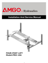
SINGLE POST LIFT
Model:SL-6

CONTENTS
I. PRODUCT FEATURES AND SPECIFICATIONS ..................................................................... 1
II. INSTALLATION REQUIREMENT ..................................................................................3
III. STEPS OF INSTALLATION ............................................................................................. 5
IV. EXPLODED VIEW ................................................................................................ 13
V. TEST RUN ............................................................................................................ 15
VI. OPERATION INSTRUCTIONS ................................................................................. 17
VII. MAINTENANCE SCHEDULE ................................................................................... 18
VIII. TROUBLE SHOOTING ........................................................................................ 19
IX. PARTS LIST FOR SL-6 .......................................................................................... 20

1
I.
PRODUCT FEATURES AND SPECIFICATIONS
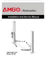
CHAIN-DRIVE SINGLE POST MODEL SL-6 FEATURES
· Compact design.
· Hydraulic cylinders, designed and made on ANSI standard, utilizing NOK oil seal in
cylinder.
· Self-lubricating UHMW Polyethylene sliders and bronze bush.
· Manual release safety lock, two-stage lock system
· Super-symmetric arms design with 3-stages front arms and 2-stages rear arms.
· Stackable and screwed type rubber pad.
Fig.1
MODEL SL-6 SPECIFICATIONS
Model
Style
Lifting
Capacity
Lifting
Time
Lifting
Height
Overall
Height
Overall
Width
Minimum Pad
Height
Motor
SL-6
Chain-drived
6,000 lbs
32S
71 7/8”-77 1/8”
108 7/8”
80”
4 1/8”-9 1/4”
2.0HP

2
Arm Swings View
Fig.2

3
II.
INSTALLATION REQUIREMENT
A. TOOLS REQUIRED
Rotary Hammer Drill(Φ19) Carpenter’s Chalk
Hammer Screw sets
Level Bar Tape Measure(7.5mm)
English Spanner(12″) Pliers
Wrench set:(10#、13#、14#、12# Socket Head Wrench:(4#、5#、6#)
17#、19#、24#、30#)
Fig.3

4
B. SPECIFICATIONS OF CONCRETE (See Fig. 4)
Specifications of concrete must be adhered to the specification as following.
Failure to do so may result in lift and/or vehicle falling.
1. Concrete must be thickness 4’’ minimum and without reinforcing steel bars and must
be dried completely before the installation.
2. Concrete must be in good condition and must be of test strength 3,000psi minimum.
3. Floors must be level and no cracks.
C. POWER SUPPLY
The electrical source must be 2HP minimum. The source cable size must be 2.5mm²
and in good condition of contacting with floor.
95
Fig.4
Concrete Intensity must be 3,000PSI minimum
More than 4’’

5
III.
STEPS OF INSTALLATION
A. Location of installation
Check and insure the installation location (concrete, layout, space size etc.) is suitable for lift
installation.
B. Check the parts before assembly
1. Packaged lift and hydraulic power unit (See Fig. 5)
Column
Power Unit
Base
Carriage
Fig.5

6
2. Take off the packaging on the machine. Take off the packing rack.
3. Move aside the parts and check the parts according to the shipment parts list(See Fig.6 & 7)
Fig.6
4. Check the parts of the parts bag according to the parts bag list (See Fig.8)
Fig.7
Fig.8
31

7
C. Lay the base flat to the ground, confirm installation place according to the ground
state, the main purpose is to save space. (See Fig.9)
D. Install column and lift platform
1. Lay the column flat to the ground.(See Fig.10)
2. Connecting oil hose of cylinder(See Fig.11)
1
Fig 10
Pull open carriage
about 200mm
Fig.11
Fig.9
2
Connect oil hose to cylinder connector

8
3. Fix column to the base plate. (See Fig.12)
4. Fix lifting platform to carriage.(See Fig.13)
Fig.12
Fig.13
3
5
6
7
4
9
7
6
8

9
E. Install motor fixed plate, power unit and oil hose(See Fig.14)
Note: Tighten the oil hose fitting and power unit fitting to avoid oil leakage; Pay
attention to the direction of power unit fitting.
Fig.14
Tighter the screw with 19#
wrench set after install
power unit fitting.
17
43
80

10
NO NO
A2A2
A1
T1
T2
T3L3
L2
L1
M
~
G
N
L
外
接
电
源
按钮开关
F. Install plastic barrier (See Fig.15)
G. Connect the power source according to the data on plate of power unit
Note: For the safety of operators, the power wiring must contact the floor well
Single phase motor (See Fig. 27)
1. Connecting the two power supply lines (active wire L and neutral wire N) to terminals of AC
contactor marked L1, L2 respectively.
2. Connecting the two motor wires to terminals of AC contactor marked T1, T2.
3. Connecting A2 to L2 of AC contactor.
4. Connecting terminal A1 of AC connector to terminal 4# of push button;
Connecting terminal L1 of AC connector to terminal 3# of push button;
20
24
25
Clip support
26
Fig.15
The plastic barrier
pass through from
here
Clip support
Single phase
Fig.16
Push button
Push button
Power supply

11
H. Install lifting arms(see Fig.17); Lowing the carriages down to the lowest position, then
use the 6# wrench to loosen the nut (See Fig. 18)Adjust the arm lock as arrow
direction (See Fig. 19). Adjust moon gear and arm lock to make it to be good
engagement, then tighten the nut of arm lock (See Fig. 20).
Adjust the screw
Tighten the screw
Fig.20
Fig.17
Fig.18
Snap Ring
Loosen the screw
Fig.19

12
I. Tighten all the hydraulic fittings, and fill the reservoir with hydraulic oil.
Note: In consideration of Hydraulic Power Unit’s durability and keep the equipment
running in the perfect condition, please use Hydraulic Oil 46#.
J. Using level to measure and adjust the column to be vertical .
H. Fix the anchor bolts
1. Prepare the anchor bolts (See Fig. 22)..
2. Using the prescribed rotary hammer drill, and drill all the anchor holes and install the
anchor bolts. Make the columns plumbness, and adjusting with the shims if not, then
tighten the anchor bolts (See Fig. 23).
Note: Torque of Anchors is 150N.m .Minimum embedment of Anchors is 3-1/2”
Use level to measure the
column by front and side
to make sure the column
is vertical
34/34A Level adjusting shim
Fig.22
Fig.23
35
Fig.21
Drilling
Clearing
Expand
3-
1/2’ ’

13
Ⅳ. Exploded View
Model:SL-6
Fig.24

14
Cylinder exploded view
Exploded view of manual power unit
110V/60Hz/1 phase
Fig.26
Fig.25

15
Illustration of hydraulic valve for hydraulic power unit
Power unit of 110V/60Hz/1PH(Fig.27)
V.
TEST RUN
1. Adjust the lower speed (See Fig.28)
You can adjust the lower speed of the lift if needing: Loosen the Fixing Nut of the
Throttle Valve, and then turn the Throttle Valve clockwise to decrease the lower speed,
or counterclockwise to increase the lower speed. Do not forget to tighten the Fixing Nut
after the lower speed adjustment has been done.
Clockwise to decrease the
down speed Counterclockwise to increase
the down speed
Oil return
port
Oil output port
Solenoid valve
Check valve
Relief
valve
Throttle valve
Fig.27
Fig.28
Fixing nut
Throttle valve
Fixing nut
Throttle valve

16
2. Test with load
After finishing the above adjustment, test running the lift with load. Run the lift in low
position for several times first, make sure the lift can rise and lower without abnormal
phenomena. And then test run the lift to the top completely. If there are anything
improper, repeat the above adjustment.
NOTE: It may be vibrated when lifting at start, please lifting it with load for several
times, the air would be bled and the vibration would be disappeared
automatically.
Circuit Diagram of Hydraulic System
1 Filter
2 Gear pump
3 Relief valve
4 Check valve
5 Explosion-proof valves
6 Cylinder
7 Motor
8 Release valve
9 Throttle valve
10 Oil tank
Fig.29

17
DOWN
VI.
OPERATION INSTRUCTIONS
To lift vehicle
1. Keep clean of site near the lift;
2. Position lift arms to the lowest position;
3. To shortest lift arms;
4. Open lift arms;
5. Position vehicle beside of the lifting arm, cab should at the other side of the column;
6. Move arms to the vehicle’s lifting point;
Note: The four lift arms must at the same time contact the vehicle’s lifting point where
manufacturers recommended
7. Turn on the power QS1 and push the button , raise the lift until the rubber
pad full contact the car and ensure it’s safe.
8. Continue raise the vehicle to the desired height and make sure the vehicle is steady
when the lift is rising, then release the “Up” button.
9. Press the button to low down the lift onto the safety lock. Confirm the
safety device at normal working condition, then the vehicle is ready to repair.
To lower vehicle
1. Be sure the clearance of around and under the lift, only leaving operator in lift area;
2. Push button “UP” to raise the vehicle slightly, and then release the safety device,
lower vehicle by pushing the down button; stop lowering when above ground 300mm,at
this moment should push button ”K” at side, then buzzer will ring and lift lower to ground
3. Open the arms and position them to the shortest length;
4. Drive away the vehicle.

18
VII.
MAINTENANCE SCHEDULE
Monthly:
1. Re-torque the anchor bolts to 150 N.M;
2. Check all connectors, bolts and pins to insure proper mounting;
3. Lubricate cable with lubricant;
4. Make a visual inspection of all hydraulic hoses/lines for possible wear or leakage;
5. Check Safety device and make sure proper condition;
6. Lubricate all Rollers and Pins with 90wt. Gear oil or equivalent;
Note: All anchor bolts should take full torque. If any of the bolts does not function for any
reason, DO NOT use the lift until the bolt has been replaced.
Every six months:
1. Make a visual inspection of all moving parts for possible wear, interference or damage.
2. Check and adjust as necessary, equalizer tension of the cables to insure level lifting.
3. Check columns for plumbness.
4. Check Rubber Pads and replace as necessary.
5. Check Safety device and make sure proper condition.
/