Page is loading ...

FOUR-POST LIFT
Model:409/410/412/
409A/410A/412A /412AX
Original

CONTENTS
Product Features and Specifications ..................................................... 1
Installation Requirement .................................................................... 2
Steps of Installation .......................................................................... 4
Exploded View ................................................................................. 33
Test Run ......................................................................................... 44
Operation Instruction ....................................................................... 47
Maintenance ................................................................................... 48
Trouble Shooting ............................................................................. 49
Scarping of Equipment ..................................................................... 49

1
I. PRODUCT FEATURES AND SPECIFICATIONS
4-POST MODEL 409(A440) FEATURES
· Electric control operation system.
· Mechanical self-lock and air-drived safety release.
· Electrical hydraulic power system, cable-drived.
· Non-skid diamond platforms.
· Adjustable platform and adjustable safety lock ladders.
· Adjustable turnplate pockets (Only models with alignment function)
· Optional Jack: With hand pump/Pneumatic pump/Controlled by power unit.
. Optional Turnplates
SPECIFICATIONS
Model
Lifting
Capacity
Lifting
Height
Lifting
Time
Overall
Length
(Inc.
Ramps)
Overall
Width
Width
Between
Columns
Motor
409
4000KG
1865mm
46S
5512mm
3208mm
2852mm
3.0HP
410
4500KG
1865mm
46S
5910mm
3356mm
3000mm
3.0HP
412
5500KG
1865mm
60S
6012mm
3208mm
2852mm
4.0HP
409A
4000KG
1915mm
46S
5512mm
3208mm
2852mm
3.0HP
410A
4500KG
1915mm
46S
5910mm
3356mm
3000mm
3.0HP
412A
5500KG
1915mm
60S
6012mm
3208mm
2852mm
4.0HP
412AX
5500KG
1915mm
60S
6012mm
3356mm
3000mm
4.0HP
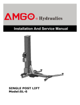
409/410/412
Fig.1
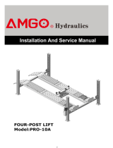
409A/410A/412A /412AX
Fig.2

2
II. INSTALLATION REQUIREMENT
A. TOOLS REQUIRED
Rotary Hammer Drill (Φ19)
Hammer
Level Bar
English Spanner (12")
Ratchet Spanner With Socket (28
#
)
Wrench Set
(10
#
, 12
#
, 13
#
, 14
#
, 17
#
, 19
#
, 24
#
, 30
#
)
Carpenter’s Chalk
Screw Sets
Tape Measure (7.5m)
Pliers
Socket Head Wrench (3
#
, 5
#
, 6
#
)
Lock Wrench
Fig. 3

3
B. Equipment storage and installation requirements.
The equipment should be stored or installed in a shady, normal temperature, ventilated
and dry place.
C. SPECIFICATIONS OF CONCRETE (See Fig. 4)
Specifications of concrete must be adhered to the specification as following.
Failure to do so may result in lift and/or vehicle falling.
1. Concrete must be thickness 200mm minimum and without reinforcing steel bars,
and must be dried totally before the installation.
2. Concrete must be in good condition and must be of test strength 3,000psi
(210kg/cm²) minimum.
3. Floors must be level and no cracks.
D. AIR SUPPLY
Air pressure requirement: 0.5Mpa~0.8Mpa, Air line size ¢8×¢6 and ¢6×¢4.
E. POWER SUPPLY
The electrical source must be 3HP minimum. The source cable size must be 2.5mm²
and in good condition of contacting with floor.
Fig. 4
Concrete intensity must be 3000psi minimum

4
III. STEPS OF INSTALLATION
A. Location of installation
Check and insure the installation location (concrete, layout, space size etc.) is
suitable for lift installation.
B. Check the parts before assembly
1. The equipment should be unload and transfer by forklift.
2. Packaged lift and hydraulic power unit (See Fig. 6).
3. Open the outer packing carefully (See Fig. 7).
Shipment Parts List
4. Take off the drive-thru ramps and columns (See Fig. 8).
Control Box
Power-side Platform
Drive-in Ramp
Offside Platform
Cross Beam
Column
Fig. 6
Fig. 7
Fig. 8
Parts Box
Fig.5
Power Unit

5
5. Loose the screws of the upper package stand, take off the offside platform, take out
the parts inside the power-side platform, than remove the package stand.
6. Move aside the parts and check the parts according to the shipment parts list
(See Fig. 9 and fig10).
6.1 Model 409/410/412
6.2 Model 409A/410A/412A/412AX
Fig.9
Fig.10

6
7. Open the carton of parts and check the parts according to the parts box list
(See Fig. 11 and 12).
7.1 Model 409/410/412
7.2 Model 409A/410A/412A/412AX
Fig. 11
Fig. 12

7
8. Check the parts of the parts bag according to the parts bag list (See Fig. 13 and 14).
8.1 Model 409/410/412
8.2 Model 409A/410A/412A/412AX
Fig. 13
Fig. 14

8
C. Use a carpenter’s chalk line to establish installation layout as per Table 1
Make sure the size is right and base is flat (see Fig. 15).
Note: Reserve space front and behind the installation site.
D. Install cross beams (See Fig. 15).
A
B
C
409, 409A
4600mm
3208mm
5608mm
410, 410A
4998mm
3356mm
6020mm
412, 412A
5100mm
3208mm
6025mm
412AX
5100mm
3356mm
6105mm
3
1
3
Car in Direction
Use a carpenter’s chalk line to
establish installation layout
Hole towards inside
2
Fig. 16
Fig. 15

9
E. Fix the anchor bolts
1. Prepare the anchor bolts (See Fig. 17).
2. Using the prescribed rotary hammer drill, and drill all the anchor holes and install the
anchor bolts. Do not tighten the anchor bolts (See Fig. 17).
Note: Anchor bolts driven into the ground at least 150mm
F. Install the safety ladders
1. Take off the pulley safety cover and unscrew the four upper nuts of the Safety ladders,
and then adjust the four lower nuts to be at the same position. Withdraw the
Slack-cable safety lock of the cross-beam to insert the safety ladder in, raise the
safety ladder, and screw the upper nuts (See Fig. 19).
Nut
Spring washer
Washer
Fig. 17
Fig. 19
Fig. 17
Safety ladder is inserted between
limit pins of the cross-beam
5
6
Safety Ladder is
inserted between
Limit Pins
Drilling
Clearing
Expand
5
Safety
Ladder
Limit Pin
Limit Pin
150mm

10
2. Install safety ladders (See Fig. 20).
G. Put the cross beams at the same height (See Fig. 21).
7
Fig. 20
Safety ladder pass through
the hole of the top plate,
then tighten the two nuts
Fig. 21
This height should
be the same for
four safety ladders
The four primary safety
locks are adjusted to be
locked to the safety
ladders at the same
time
Lifting both cross beams
to the same height, it is
recommended to about 1
meter height
6
Lifting Both Cross Beams to the same height

11
H. Install power-side platform.
Put the power-side platform upon the cross beams by fork lift or manual, offset the cross
beams to the outside till the pulleys of both platforms can set up into the cross beams
(See Fig.22 23). Install the power-side platform and screw up the bolts (Fig 24).
Fig. 23
2 Pulleys installation
View A
Offset the cross beam lean
outward when putting the
power-side platform on the
cross beams
Power-side Platform
4 Pulleys installation
View B
A
B
Fig. 22
Tighten the power-side platform
and cross beam with bolts M16*40
Fig. 24

12
I. Assembly offside platform and slider block, check the plumbness of columns with level,
adjusting with the shims if not, and then tighten the anchor bolts (See Fig. 25 26).
Note: The tightening torque for the anchor bolt is 150N.m
Fig. 26
Using the Ratchet Spanner
With Socket to tighten the
bolts
Install the slider block on
the cross beam
C view
Fig. 25
Power-side platform
3-15
3-16
3-14
94
Offside platform

13
J. Illustration for cable installation
1. Pass through the cables from the platform to the columns according to the number of
the cables (See Fig. 27).
No.
Model
④
409/409A Length
(inc. connecting fitting)
3250mm
9250mm
4850mm
7654mm
410/410A Length
(inc. connecting fitting)
3725mm
10125mm
5325mm
8520mm
412/412A Length
(inc. connecting fitting)
3775mm
10325mm
5380mm
8710mm
412AX Length
(inc. connecting fitting)
3850mm
10400mm
5455mm
8785mm
Fig. 27
A
C
D
B
C
A
B
D
72
70
71
73

14
2. The cable pass through the cross beam to top plate of columns and be screwed with
cable nuts.(See fig 28, 29) Installation for Cable limit Pin on cross beam (See Fig. 24).
Cable pass through between the
big pulley and tension pulley
View D
Fig.28
Cable pass through top plate
and be screwed with cable nuts.
View E
Fig.29
7
D
E
Limit Pin
Install Limit Pin
60
B
Pulle
y
60
A
View F
Fig 30
Cable
After Installation
F

15
3. Illustration for platform cables (See Fig. 31 & 32 & 33).
Fig. 33
Cable ④
Cable ②
Cable ②
Cable ①
Cable ④
Cable ③
Cable ②
Cable ④
Hex Bolt M10*120
19
Cable ①
Cable ②
Cable ④
Cable ④
Cable ③
Cable ②
Fig. 31
Fig. 32

16
K. Install oil-water separator, solenoid air valve, control box and power unit.
1.For electric control air-operated four post lift (See Fig. 34 & 35).
Item
Part No.
Description
QTY
20
10420145
Oil-water Separator
1
21
10420146
Straight Fitting for Air Line
1
22
10209009
Cup Head Bolt
6
23
10420076
90
0
Fitting for Air Line
1
24
10201034
Bleeding Plug
1
25
10420147
Straight Fitting for Air Line
1
26
10420077
Air Solenoid Valve
1
27
10420148
Washer
2
28
10420149
Cup Head Bolt
2
29
11420150
Cover of Air Solenoid Valve
1
30
10420045
Washer
28
31
10420151
Straight Fitting for Air Line
1
32
10420018
Self locking Nut
6
33
10420016
Control Box
1
34
10420153
Cup Head Bolt
9
35
81523001/81523002
Electrical Power Unit
1
1
20
21
31
33
22
23
24
25
26
27
28
29
32
30
22
34
35
Oil-water separator and Air Solenoid Valve
Fig. 34
Air outlet
Air inlet
Oil-water separator air flow direction
Fig. 35

17
6*4 Black Air
Line
L. Install hydraulic system (See Fig. 36).
Note: Oil hoses and oil return pipe connected to oil cylinder must be passed above the
cable and cylinder inlet port must swing upward to avoid the oil hose and
View H
Fig.38
76
Oil Hose & Air
lines pass
through
retainer
Swing up the fitting of cylinder
Installation of return Hose and inlet Hose
View G
Fig.36
H
G
I
J
Protective Ring
79
80
84
Wire of cross
beam limit switch
and oil return
hose come from
this hole
Install Oil return hose
of cylinder.
View J
Fig.39
84
78
63
View I
Fig.37

18
M. Install air-line system
1. Connecting front and rear Cross Beam cylinders by using 6*4 black air pipe. (the
actual length of air line can be cut by user) (See Fig.40)
2, Cut the 6*4 black air pipe by scissor between two retainers, then connect the air line
with T fitting. (See Fig. 41).
3. Connecting the solenoid valve using 6*4 black air pipe (the actual length of air line
can be cut by user) (See Fig. 42).
Rear
Cross Beam
Front
Cross Beam
Power-side
platform
Air pipe through
retainer
air pipe
Power unit
K
L
89
90
Power-side platform air pipe
connect with T fitting
6*4 black air pipe
connect the solenoid
valve
Fig.40
L view
Fig.42
K view
Fig.41
88
/