Central Hydraulics 94780 Installation, Operation and Maintenance Manual
- Type
- Installation, Operation and Maintenance Manual
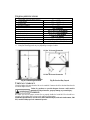
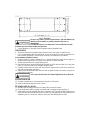
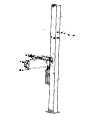
Central Hydraulics 94780 is a top-of-the-line 2-post lift with a lifting capacity of 10,000 lbs. It features a rise height of 78 1/8" (1985mm), a column height of 151 3/16" (3840mm), and a drive-thru clearance of 99 3/8" (2524mm). The lift is equipped with a 2HP, single-phase, 60Hz, 220V motor and has a maximum lifting speed of 12fpm.
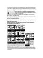
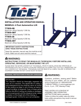
The 94780 is perfect for a variety of automotive repair and maintenance tasks, including oil changes, tire rotations, brake repairs, and engine work. It is also ideal for use in body shops and other commercial settings.
Some of the key features of the 947
Central Hydraulics 94780 is a top-of-the-line 2-post lift with a lifting capacity of 10,000 lbs. It features a rise height of 78 1/8" (1985mm), a column height of 151 3/16" (3840mm), and a drive-thru clearance of 99 3/8" (2524mm). The lift is equipped with a 2HP, single-phase, 60Hz, 220V motor and has a maximum lifting speed of 12fpm.
The 94780 is perfect for a variety of automotive repair and maintenance tasks, including oil changes, tire rotations, brake repairs, and engine work. It is also ideal for use in body shops and other commercial settings.
Some of the key features of the 947


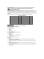
-
 1
1
-
 2
2
-
 3
3
-
 4
4
-
 5
5
-
 6
6
-
 7
7
-
 8
8
-
 9
9
-
 10
10
-
 11
11
-
 12
12
-
 13
13
-
 14
14
-
 15
15
-
 16
16


Central Hydraulics 94780 Installation, Operation and Maintenance Manual
- Type
- Installation, Operation and Maintenance Manual
Central Hydraulics 94780 is a top-of-the-line 2-post lift with a lifting capacity of 10,000 lbs. It features a rise height of 78 1/8" (1985mm), a column height of 151 3/16" (3840mm), and a drive-thru clearance of 99 3/8" (2524mm). The lift is equipped with a 2HP, single-phase, 60Hz, 220V motor and has a maximum lifting speed of 12fpm.
The 94780 is perfect for a variety of automotive repair and maintenance tasks, including oil changes, tire rotations, brake repairs, and engine work. It is also ideal for use in body shops and other commercial settings.
Some of the key features of the 947
Ask a question and I''ll find the answer in the document
Finding information in a document is now easier with AI
Other documents
-
Challenger Lifts E10 Installation, Operation & Maintenance Manual
-
 REDHEAD WW-3454 Installation guide
-
Vestil FLP-20-SS Installation guide
-
TUXEDO Two Post Surface Mounted Lifts TLT210-A/TLT210-AS/TLT210-XT/TLT211-AS User manual
-
 TCE T11000-2OH-33 Operating instructions
-
 TCE T9000-4S User manual
-
-
-
Rotary SPOA3TS-5SC-EH2 Owner's manual
-
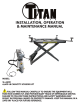 Titan Lifts SL-6600 Installation, Operation & Maintenance Manual


