Midmark Dental Light (Halogen) Operating instructions

Type
Operating instructions

This manual is also suitable for

1
© 2012 Midmark Corp. | 60 Vista Drive Versailles, OH 45380 USA | 1-800-643-6275 | 1-937-526-3662 |
TP201 Rev. A
Track Light Monitor Suspension Tube Changeover
Applies to Models:
153829 & 153830
153963 & 153964
Special Tools:
none
Language of origin: English
Note
Use when installing new suspension tubes to fit a room with a different ceiling height.
004-1025-99 (4/3/17)
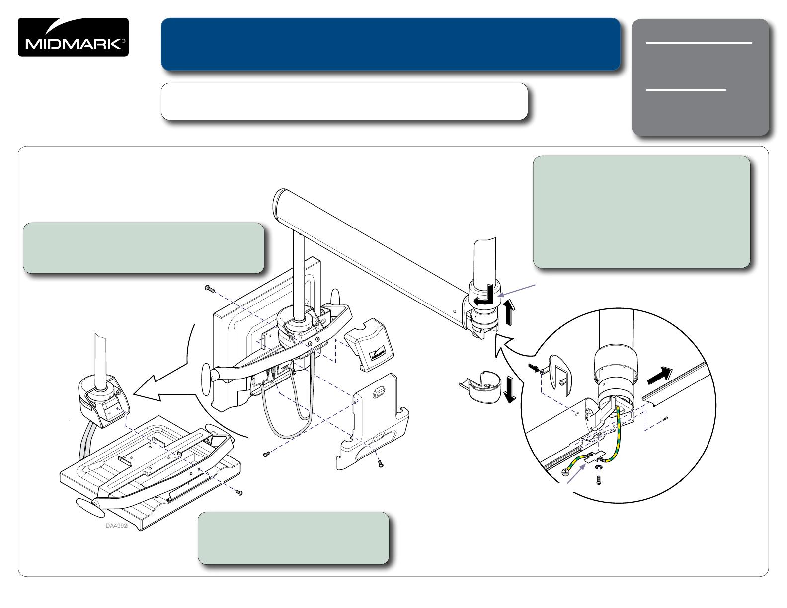
Step 3: Access A/V cable.
A) Rotate top cover to separate it from the
bottom cover, then slide it up the tube.
B) Remove bottom cover.
C) Push in on tabs and remove end cap.
D) Remove screws and bracket.
E) Remove screw and slide cable shield out
of the flex arm assembly.
Top Cover
Bottom Cover
Flex Arm
Step 1: Remove monitor mount covers.
A) Remove covers.
B) Disconnect cables from monitor.
Step 2: Remove monitor.
A) Rotate monitor parallel to floor.
B) Remove two screws and monitor.
End Cap
Bracket
Cable
Shield
midmark.com
Style G
2
© 2012 Midmark Corp. | 60 Vista Drive Versailles, OH 45380 USA | 1-800-643-6275 | 1-937-526-3662 |
TP201 Rev. A
OUT
Step 4: Disconnect A/V cable.
A) Drop A/V cable out of the flex arm channel.
B) Disconnect all cable connections.
Step 5: Remove Monitor Flex Arm.
A) Slide top cover up suspension tube.
B) Loosen set screw and slide tube collar up tube.
C) When you remove the key, flex arm will fall free of
suspension tube.
Top Cover
Key
Tube Collar
midmark.com
Style G
3
© 2012 Midmark Corp. | 60 Vista Drive Versailles, OH 45380 USA | 1-800-643-6275 | 1-937-526-3662 |
TP201 Rev. A
DA3779i
Step 6: Remove Light Flex Arm.
A) Slide cover up suspension tube.
B) Loosen set screw and slide tube collar up tube.
C) When you remove the key, flex arm will fall free of
suspension tube.
D) Disconnect light harness.
Key
Tube Collar
Cover
Step 7: Install New Suspension Tubes.
A) Remove two set screws from each trolley.
B) Unscrew old suspension tubes from the trolleys.
C) Thread cables thru and screw new tubes into trolleys.
D) Secure tubes by installing two set screws in each trolley.
Note: The Light tube (thinner diameter) is longer than the monitor tube.
DA3767i
DA3767i
Old
New
Set
Screws
midmark.com
Style G
4
© 2012 Midmark Corp. | 60 Vista Drive Versailles, OH 45380 USA | 1-800-643-6275 | 1-937-526-3662 |
TP201 Rev. A
DA3769i
Step 8: Remove Transformer from the Foot End of the Track.
A) Remove two screws and the end cap.
B) Remove four screws and the cover.
C) Disconnect the blue and brown wires, on end cap side of the transformer.
D) Disconnect the blue, brown and ground wires from the other side of the transformer.
E) Remove three screws and transformer mounting bracket.
F) Unscrew bumpers from track.
End Cap
Cover
Step 8C
Transformer
Bumpers
midmark.com
Style G
Color Page
5
© 2012 Midmark Corp. | 60 Vista Drive Versailles, OH 45380 USA | 1-800-643-6275 | 1-937-526-3662 |
TP201 Rev. A
Step 9: Remove A/V Cable Clips, Rails and Trolleys from Track.
A) Remove A/V cable side outer rail. (Rail wedges into gap between backer board and track).
B) Remove four screws and the A/V source cover.
C) Remove A/V cable side inner rail (secured by three screws on the outside of track).
D) Remove A/V cable clips and overmold to release cable from track.
E) Roll the light trolley off the end of the track (allow light harness to dangle from track).
F) Roll monitor trolley off the end of the track (A/V cable moves with trolley).
A/V Source
Cover
A/V Cable
Clips
Outer Rail
Inner Rail
Light Trolley
Monitor Trolley
DA3771i
midmark.com
Style G
6
© 2012 Midmark Corp. | 60 Vista Drive Versailles, OH 45380 USA | 1-800-643-6275 | 1-937-526-3662 |
TP201 Rev. A
Step 10: Use Colored Tape to Set A/V Cable for New Ceiling Height.
A) Remove four screws and the coiler bowl from the monitor trolley.
B) Maneuver the A/V cable so that the appropriate color tape for the installation
ceiling height is just visible from the bottom of the coiler bowl.
Note: Reference the chart for appropriate colored tape for specific ceiling height.
* There are NO suspension tubes available for ceilings lower than 96" in height
Ceiling Height Tape Color
Monitor Suspension Tube
Length
PN 052-0678-0X-216
Light Suspension Tube
Length
PN 052-1845-0X-216
96*/98 in.
(244/249 cm)
Red
5.69 in. (15 cm)
PN 052-0678-00-216
11.71 in.
(30 cm)
PN 052-1845-00-216
99/102 in.
(251/259 cm)
Orange
8.69 in. (22 cm)
PN 052-0678-01-216
15.71 in.
(40 cm)
PN 052-1845-01-216
103/106 in.
(262/269 cm)
Yellow
9.69 in. (25 cm)
PN 052-0678-02-216
19.71 in.
(50 cm)
PN 052-1845-02-216
107/110 in.
(272/279 cm)
Green
10.69 in. (27 cm)
PN 052-0678-03-216
23.71 in.
(60 cm)
PN 052-1845-03-216
111/114 in.
(282/290 cm)
Blue
14.69 in. (37 cm)
PN 052-0678-04-216
27.71 in.
(70 cm)
PN 052-1845-04-216
115/118 in.
(292/300 cm)
Violet
18.69 in. (47 cm)
PN 052-0678-05-216
31.71 in. (80 cm)
PN 052-1845-05-216
119/122 in.
(302/310 cm)
Gray
22.69 in. (58 cm)
PN 052-0678-06-216
35.71 in.
(90 cm)
PN 052-1845-06-216
123/126 in.
(312/320 cm)
Brown
26.69 in. (68 cm)
PN 052-0678-07-216
39.71 in.
(101 cm)
PN 052-1845-07-216
>126 in. (320
cm)
Black
30.69 in. (78 cm)
PN 052-0678-08-216
43.71 in.
(111 cm)
PN 052-1845-08-216
Coiler Bowl
Tape
Step 11: Install Trolleys, Cables, Covers , Monitor & Light.
A) Reference Steps 1 - 10 in reverse order to reassemble the track light monitor.
midmark.com
Style G
Color Page
  • Page 1 1
  • Page 2 2
  • Page 3 3
  • Page 4 4
  • Page 5 5
  • Page 6 6

Midmark Dental Light (Halogen) Operating instructions

Type
Operating instructions
This manual is also suitable for

Ask a question and I''ll find the answer in the document

Finding information in a document is now easier with AI