English-8
© 2011 Midmark Corp. | 60 Vista Drive Versailles, OH 45380 USA | 1-800-643-6275 | 1-937-526-3662 | www.midmark.com
DA3419-1i
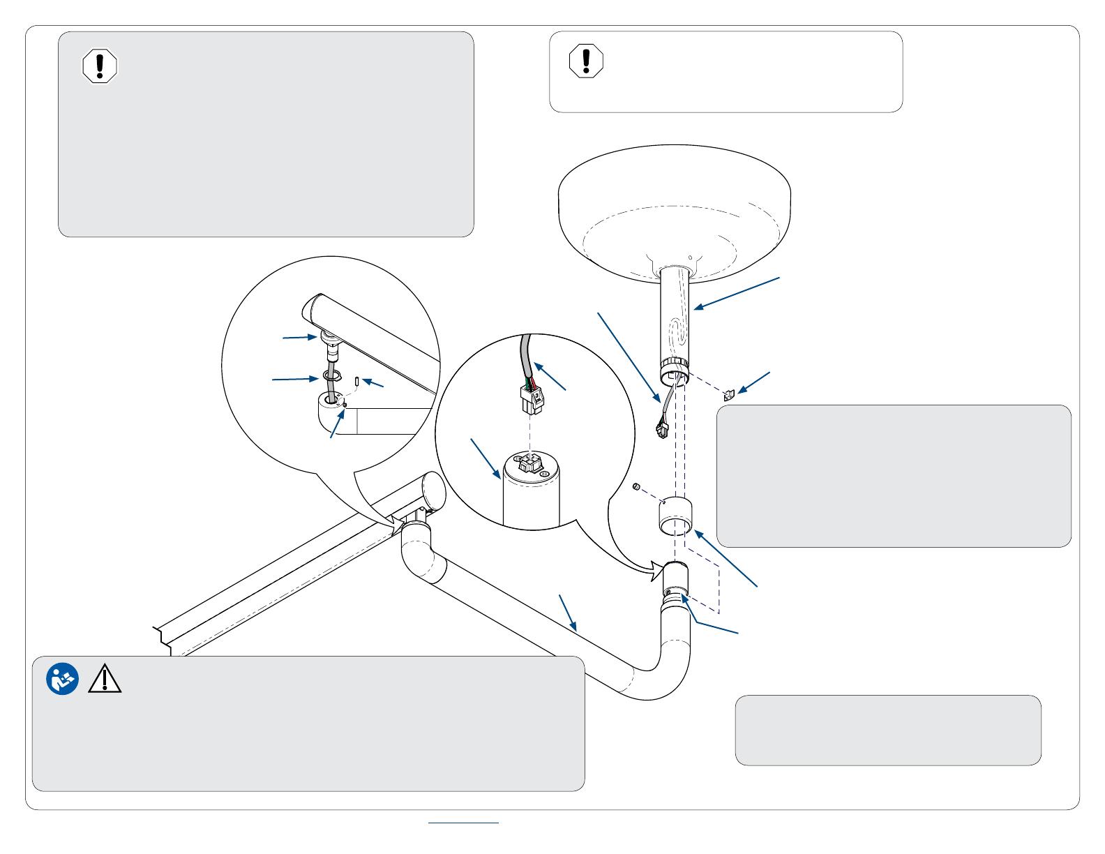
Equipment Alert
Use an assistant to secure fixed arm assembly
when performing following steps. Failure to do
so could result in damage to lighthead.
Step 10: Installation Light Arm.
A) With rounded edge of collar upward, slide collar
onto suspension tube.
B) Tighten set screw (1) to temporarily hold collar
in place.
C) Fold excess length of wire harness and push up
into suspension tube as shown.
Caution - Equipment Alert
To ensure quiet operation, apply a thin coat of lubricant
(included w/light) to inside of suspension tube and bearing
shaft of fixed arm before performing the following steps.
Step 11: Installation Fixed Arm.
A) Connect wire harness to connector in the end of fixed arm.
B) Insert fixed arm into suspension tube, then install key thru
hole so that it fits into groove of fixed arm.
C) Loosen set screw (1) and slide collar all the way down, and
tighten set screw (1).
Collar (w/ rounded edge up.)
(1) Set
Screw
Suspension Tube
Key
Wire Harness
Wire
Harness
Fixed
Arm
Groove
(2) Set
Screw
Stop
Pin
Stop
Ring
Cover
Ring
Flex
Arm
Step 13: Verify Operation of Light.
Note: If necessary, refer to User’s Manual for operation.
Fixed
Arm
Step 12: Installation of Stop Ring & Pin.
A) Position tab of rotation stop ring in line with flex arm so that it is facing lighthead.
B) Insert flex arm shaft into curved arm assembly and secure with set screw (2).
C) Lift cover ring and install stop pin into hole in curved arm assembly.


