Page is loading ...

!
WESTERN PRODUCTS
7777 NORTH 73RD STREET
PO. BOX 23045
MILWAUKEE. WISCONSIN 53223
bb A UIVISION OF DOUGLAS DYNAMICS INí.
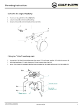
Box No. 60254
Model 2200 Datsun 4x4
Front Frame Lift-Mount
INSTALLATION INSTRUCTIONS
\~
~,
.. " "j':
L.:'\ . ~.~ '~
~\.
1\---
\,\ -
,\,)----
~61/2" x 4" BOLTS
I 112 x 1-12 SOL TS
\ - -
RHOMMfNOfO JASHllER TORQUE CHART
SllE T DADllr III
0GRADE 1 C) GRADE 5 , 0 GRADE.
! .. ;'D "9T J
~ló 'II ii II! ,'H
!IH :¡, 19 3i -Iii
j-IH .'.1 .'-1 46 4,H
/.'., .. 30 ~H,
117 -IJ ..!! l!! II !!
9/16 - il 66 '10 165
5/8 -ii 93 1!! 225
3/4 -10 150 7!! 370
7/8 -9L07 318 591
,-BJO 583 893
T "IIW' tur(l~.t. ..alul.~ "J.n)l" fO hi. moun, fastener, ,.-cern ,hoSt nOlPr1
I"~ tl'e 'nSf'uci1oni ''hffrp r'T10lfon .,1 ite!ired
AS VIEWED FROM DRIVER SIDE
LIFT-MOUNT UNIT
o
F--- .
. \\
L~_;-_= .
õL /
~ I I.'l
~ '" / !
--- i,
'-~
BUMPER :
ST~~~
o
COUPUNG lUG
MINIMUM VEHICLE
RECOMMEND A TIONS
Aux. Light Kit
REAR 8ALLAST-300
to 5001bs. when blade
is attached.
CLAP BAR
VEHICLE FRAM
THRUS ARM UNIT
5/8" x 1.3/4" SOL T
IMPORTANT: Read instructions before assembling. Bolts should be finger tight until the installation is completed to allow sufficient adjustmet
for aligning holes and locating parts to vehicle frame., Preventive maintenance can prevent accidnts. Regularly inspct all compoents and
repair or replace any worn, loose, Or damaged parts immediately. Remember to use standard method and praice when attacing snolow
including wearing safety glasses during drillng.
LIFT-MOUNT ASSEMBLY:
1. Disconnect park' and turn lights at plug behind bumper. Remove bumper and brackets. (Bumpe bracket bolts can be remoed from
inside engine compartment.
2. Remove front protector unit and skid plate, (These parts should be retained for reinstallation in event the snowplow is removedJ For ease
of installation remove tow hook during lift-mount assembly and reinstall after installation is complete.
3. Attach the lift-mount unit to the inside of the vehicle frame using the furnished 5/8" x 1-3/4" bolts, flatwashers to slot in vehicle frame
and locknuts. In5taIl1/2" x 1-1/2" bolts, flatwashers to slot in frame and locknuts into front mounting holes of lift-mount and vehicle frame.
4. Attach thrust arm to vehicle frame rail directly in front of control arm mounting using the clamp bar and furnished 1/2" x 4" bolts and
locknuts. Clamp bar is to be placed on inside of vehicle frame with 45" trim located at bottom rear. Attach other end of thrust arm to
bottom of lift-mount using furnished 5/8" x 2" bolts and locknuts. TIGHTEN ALL BOLTS TO CORRESPONDING TORQUE VALUES
NOTED IN FASTENER TORQUE CHART.
5. Reinstall bumper to lift-mount unit with the existing bolts and nuts using the furnished 1/4" washers at slots in bumper brackets. To aid
installation it may be necessary to remove rubber bumper pads to insert bolts through lift-mount bumper brackets. Attach bumper straps
(see inset) to side of bumper with furnished 1/4" x 1" bolt, washer and locknut. Fasten bumper strap to side of fender using the existing
screw and washer, tighten fasteners and reconnect turn lights.
6. Install plastic shields to rectangular opening located directly below headlights. (If auxiliary headlights are to be used the plastic shields
should not be installed until headlight installation is complete.! Remove hex washer head screws from outboard ends of openings, align
large hole in plastic shield and secure with existing fastener. Using small hole as a guide, drill opposite ends into metal with 9/64" dia. drill
and secure with furnished No. 10 x 1" screws. (Plastic shield is necessary to protect horn unit and wiring harnessJ
LIGHT KIT ASSEMBLY:
CAUTION: READ LIGHT KIT SUPPLEMENTARY WIRING INSTRUCTIONS BEFORE INSTALLING HEADLAMPS INTO CIRCUIT.
DO NOT drill instrument panel for mounting the toggle switch.
-Form No. 3229-8405 -1- Printed in U.S.A.

Box No. 60254
14
~
,~5 7~
~ 11'
6 17--
18-~
11
Model 2200 Datsun 4x4
Front Frame Lift-Mount
DIAG RAM AND PARTS LIST
æ,,~
~16
13-: ~ 0
1(t~
3230-8312
3231-8312
Ite Part No. Quan. Description
1
2
3
4
5
6
7
8
9
10
11
12
13
14
15
16
17
18
19
20
60275
60286
60291
60293
60294
1
1
1
2
2
2
4
4
2
2
6
4
2
2
8
4
2
2
2
2
Lift-Mount Unit
Thrust Arm Unit - Curb Side
Thrust Arm Unit - Driver Side
Clamp Bar
Bumper StrAp
Capscrew - 1/4" -20 x 1" Long
Capscrew - 1/2" -13 x 1-1/2" Long - Grade 5
Capscrew - 1/2"-13 x 4" Long - Grade 5
Capscrew - 5/8"-11 x 1-3/4" Long - Grade 5
Capscrew - 5/8"-11 x 2" Long - Grade 5
Flat Washer - 1/4"
Flat Washer - 1/2"
Flat Washer - 5/8"
Locknut - 1/4"-20 - Nylon Insert Type
Locknut - 1/2"-13 - Nylon Insert Type
Locknut - 5/8"-11 - Nylon Insert Type
Hairpin Cotter - 5/32" x 2-15/16" OIA Length
Hitch Pin - 1" x 3-112" Long
Plastic Shield
Screw No. 10 x 1" Long
90100
90107
90 128
90129
91331
91335
91337
91965
93028
60299
NOTE: Only those items indicated with a PART NUMBER are available for Service.
-2-

INSTAllATION INSTRUCTIONS LOCK SPOL - should 1M ~ whe
mounted plow IS no' in ute.
'-
No. 8 x 5/1"
SCREWS 1.1
ADJUTMENT
For - ilIa Control and Floor Bracket
Model No. 2200 Datsun 4x4
.., '. ~
No. 10 . i/r T APNG SCREWS 131
.. 10 LOCKWR
,. Position floor bracket stool 11-1/2" from edge of floor console as shown. Mark loction of the 3 mounting hoes and drill 2.9/8.'
diameter holes into the floor and 1 - 9/64" diameter hole into tunnel.
2. Assemble the floor bracket stool to floor bracket using 3-No. 10 x 3/8" long hex hea tapping sc. Pla rubb bot onto bo of
floor bracket. .
3. Assemble the Ilia Control to the floor bracket using 4-No. 8 x 518" long hex head sc.
4. Control cales wil pass through ,the passengers side of firewall. Dril per hydraulic system instruction.
5. Place assembled control in poition and secure with No. 10 )( 1" shet metal screws and lock waer.
6. Slide rubber boot down to cover attaching flange screws. 3232-16
INST A llA TIO NINSTR U CTIONS
FOR S9700BLADE GUIDE ASSEMBL Y
The following instructions simply outline the attachment of this blade guide asembly.
Step 1.
Step 2,
lower blade to ground level.
If hole IS not pre.drilled. drill one 11/32" hole. 1.3/16" down and 1" out on the outside rib
of blade. See diagram below.
Insert pointed end of clamp into coil of guide, Attach guide to rib using top hole of clamp.
Secure assembly using supplied 5i16" x 1" bolt and locknut. Tighten until guide wtli stand
alone perpendicular to road surface. .
If hole is not pre-drilled, use lower hote of clamp as locator. drill bottom hole 11/32".
Bolt luwer hole in place. F ¡nish securing top bolt.
Attach other side following above steps
ITEM
1
'2
3
4
PART NO.
59697
59694
59696
59691
59946
OUAN.
'2
DESCRIPTION
Blade Guide RoJ. S.Hook & Flag
Flag
S.Hook
Blarte Guide Rod
Clamp
Caiiscre~.. 5 t6 18. 1 Gr :?
Lacko,,' !J llì 18 Nylon Insert
~ ;:-
~
Step 3.
Step 4.
Step 5.
Step 6.
Pictorial view supplied below. Remennhe.- to use standard methods and practices IJ attaching blade guid~
including wearing safety glasses during (lrillinci.
PARTS LIST
59700 -.BLADE GUIDE ASSEMBL Y
5
64
43009.791 i
-3-

SUPPLEMENTARY LIGHT KIT - WIRING INSTRUCTIONS AND PARTS LIST I
IMPORT ANT: When using 6010 with this installation, the ground circuit of the auxiliary headlamix must be changed to coincide with the
vehicle head lamp ground circuit. (These .vehicles have the headlamp switch in the ground circuiU Paragraph III is only applicable with four
headlamps on the vehicle.
I. 60010 RECTANGULAR AUXILIARY HEADlAMP WITH
PARK/TURN. SEE DIAGRAM.
1, Remove both head lamps from auxilary headlamp housings.
Cut the double ground leads about 2" from the headlamp
socket.
2. In each headlamp housing, connec together the Park/Turn
lamp ground lead and housing ground lead (cut per Step 1)
with furnished self stripping wire connector.
3. Driver's Side - Remov strain relief from headlamp
housing. Insert the long lea of the in-line fuse holder
through the head lamp wire casing. Coronect this 'ead to
one of the 2" ground leads (other 2''' grond lead is not
use~ onheadlamp$Ocket using furnished self stripping
wire connectors. Replace strain relief and headamp in
housing.
4. Curb Side -Repat Step 3 using'3 foot wire in plac of
fuse holder.
5. Attach short lead of fuse holder to blue wire of light kit
harness using fumish self stripping wire conecor.
6. Conne 3 foot wire to long lea of fuse holde with
furnished setf stripping wi re connector.
tUT Dount
i;llDuliD LEADS
l F "OM SOCKn lEADS
MFDIII
em i-,
CIE' II
II. AUXILIARY TOGGLE SELECTOR SWITCH:
Using th lig switch bracket as 8 ~ate, _Iee a loction convenient to the opator and dril two 118" hole into the lower flang of the
intrment panel. Fasten thebrllket to the panel using furnishe No. 10 x 1" shet meta sc and lockwashlr. After attaching wires to
th switch as shown in the diagm, install th switch in the hole of the brcket and affix switch label ove swtch onto bracket.
'art No.
60229
60230
S)185
60186
59114
Ou..
1
1
1
1
6
2
2
Deiption
Suppemeterylight Kit
Ligt Switch Bracket
In-line Fuse Assmbly
Wire No. 16 x 3 Foot Long
Self Stripping Wire Connector
Tappin Screw No. 10 x 1"'
Lockwasher - No. 10
II. NOTE: FOR VEHICLES WITH FOUR RECTANGULAR HEADLAMP:
Harness No. 49057 (if not furnished in lift-munt box, 490 Kit must be purchasd separately,) repaces the No. 59805 harnes supplied with
light Kit number 6010. Follow the instllation instructions furnished with the light kit except for the two steps noted "a-R" below, when
making the installation.
Disregrd the paragraph '!ntitled "Driver's Side" and substitute "a-A" No.1.
"a-R"' No.1 _ Disconnect vehicle high bem lamps (type 1A) and seal thes plugs with furnished safety caps. Driver Side - remove existing
plug from high-low beam headlamps (type 2Al and connect male plug of harnes tQ it. Connect the short 3 terminal female harness plug to this
headlamp, and the long 3 terminal plug to the curb side headlamp. Connect the short 2 terminal plugs to the high beam lamps (type1A).
NOTE: With this harness all 4 vehicle head lamps wil operate when the toggle swtch is set to the "veicle"' position and the high beams are
selected.
"Q-R"' No.2 _ When connecting the six spde terminals to the togle switch, reverse the black and white leads from thauhown on the wiring
diagråm.
Part No. Cuan.
1
1
2
Desription
Four Lamp Adaptor Kit
Harness - Quad Rectangular Headlamps
Safety Cap (Plastic) Form No. 3224-850 i
49056
49057
59804
The following are registered. or unregistered1M Trade Marks of Douglas Dynamics. Inc.
WESTERN. ISARMATIC. Hydra-Turn. Roll-Action 1M SnowKing™
Western resrves the right under its Product Improvent Policy to change construction or design details and fumish equipment when so altere without
reference to iHustratlon or speifications use heein.
Printed in U.S.A. ..
/