Page is loading ...

~
WESTERN PRODUCTS
7777 NORTH 73RD STREET
. P.O. BOX 23045
MIL W AUKEE. WISCONSIN 53223
Box No. 60462
Model No. 250
Jeep Cherokee Wagon/Wagoneer
'84 & Later
INSTAllATION INSTRUCTIONS
RECOMMENDED FASTENER TORQUE C.HART .
UynDniii:
SIZE o GRADE 2 mGRADE 5 ~GRADE 8
1/4 - 20 6913
5/16 - 18 11 18 28
3/8 - 16 19 31 46
3/8 - 24 24 46 68
7/16 - 14 30 50 75
1i2 - 13 45 75 115
9/16 - 12 66 110 165
5/8 - 11 93 150 225
3/4 - 10 150 250 370
7/8 - 9202 378 591
1-830 58 893
METRIC GRADE 8.8 TORQUE IN FOOT POUNDS
SIZE TORQUE SIZE TORDUE
M 6 7M12 . 60
M 8 17 M14 95
M10. 35 M16 155
These torque values apply to ii ft. mount fasteners except those noted
. in the instructions where motion is desired.
MINIMUM VEHICLE
RECOMMENDA TIONS
.
. Aux~ Light Kit
Frt. Aux. Air Bag Springs
REAR BALLAST -300 Ibs.
when blade is attached.
WEIGHTS MUST BE
SECURED.
NOTE:
DIRECT HYDRA. TURN~
. HOSES AND FITTINGS
AWAY FROM STOPS.
AND PINCH POINTS.
AS VIEWED FROM DRIVER SIDE
,-- --
LIFT FRAME UNIT
/
10mm x 30mm BOLTS
2 19878t LATER - REAM
FOR 0/" x 3%" BOLT
11" x 3" BOLT (1986
8tEARlIER)
2 MOUNT UNIT
;;:~-:=
-_": -: :.= =
11" x 11A"BOlTS
IMPORTANT: Read instructions before assembling. Bolts should be finger tight until the installation is completed to allow sufficient
adj ustment for aligning holes and locating parts to vehicle frame. Preventive maintenance can prevent accidents. Regularly inspct
all components and repair or replace any worn, loose, or damaged parts immediately. Remember to use standard method 'and
practices when attaching snowplow including wearing safety glasses during drillng. Install snowplow as follows:
UFT-MOUNT ASSEMBLY:
1. Remove bumper with brackets from vehicle. On 1987 and later vehicles, disconnect ball shape vacuum tank from bottom flange
of curb end of bumper.
2. Mount unit installation:
'84 THRU '86: Align mount units to frame bumper bracket attaching holes and fasten with furnished 1 Omm x 30mm bolts, 318"
flat washers and 10mm lock washers. Secure rear of mount units using furnished ¥2" x 3" bolts and locknuts.
'87 AND LATER: Ream the single hole at tapered end of mount unit plates to accept a 0/" bolt. Temporarily loosen rubber mud
flaps adjacent to vehicle frame and insert mount units from the rear between frame and front bo support bracket. Align mount
units to frame bumper bracket attaching holes and fasten using furnished 1 Omm x 30mm bolts, 318" flat washers and 10mm lock
washers. Secure rear of mount units using furnished ¥a" x 31A" bolts and flange nuts. Secure rubber mud flaps.
3. Insert tapped hole ends of right and teft hand thrust arm units inside diagonal offset brackets of mount units and secure with
furnished ¥2" x 1%" bolts and lock washers.
4. Attach lift Frame Unit to mount plates using furnished ¥2" x 11A" bolts and locknuts through top and bottom holes in mount plates.
Fasten thrust arms to outside of vertical frame angles using furnished 0/" x 1 ¥2" bolts and locknuts.
TIGHTEN ALL BOLTS TO CORRESPONDING TORQUE VALUES NOTED IN FASTENER TORQUE CHART.
5. Loosen bumper brackets on bumper and slide each one out %". Retighten and assemble bumper to outside of mount unit plates
using furnished 7/16" x 11A" bolts, flat washers to brackets and locknuts. Replace vacuum tank removed in Step 1 .
CAUTION: To prevent damage to gas lines, brake lines, gas tank vapor lines or wiring during installation, move and replace as
necessary.
NOTE: Assemble and install balance of snowplow per instructions furnished with each respective assembly.
Form No. 13319-8701 -1- Printed in U.S.A.

20
21 ì
~
13~
Box No. 6062
Model No. 250
Jeep Cherokee WagonlWagoneer
.84 & Later
DIAGRAM & PARTS LIST
7:986 ~ EARUER
13 ~
. ~
(\~" 11
,15
19878tLATER
10
~
.~.
\i..~. ·
-~14 5
13320-8701
13321-8701
Item
1
2
3
4
5
6
7
8
9
10
11
12
13
14
15
16
17
18
19
20
21
Part No.
60398
6004
605
60739
60754
95051
9066
90099
90105
90127
90133
91334
91335
91337
91382
Quantity
1
1
1
1
1
6
6
8
2
2
2
6
6
2
2
6
6
6
4
2
2
Description
lift Frame Unit
Mount Unit - Driver Side
Mount Unit - Curb Side
Thrust Unit - Driver Side
Thrust Unit - Curb Side
Capscrew - 1 Omm-1.5 x 30mm Long - Grade 8.8
Capscrew -7/16"-14 x 1-1/4" Long - Grade 5
Capscrew - 1/2"-13 x 1-1/4 Long - Grade 5
Capscrew - 1/2"-13 x 3" Long - Grade 5 ('86 & Earlier)
Capscrew - 5/8"-11 x 1-1/2" Long - Grade 5
Capscrew - 5/8"-11 x 3-1 14" Long - Grade 5 ('87 & Later)
Locknut - 7/16"-14 - Nylon Insert Type
Locknut - 1/2"-13 - Nylon Insert Type
Locknut - 5/8"-11 - Nylon Insert Type
Flange Locknut - 5/8"-11 ('87 & Later)
Flat Washer - 3/8"
Flat Washer - 7/16"
Lock Washer - 1 Omm
Lock Washer - 1/2"
Hairpin Cotter - 5/32" x 2-15/16" OIA Length
Hitch Pin - 1" x 3-1/2" Long
95173
91965
93028
NOTE: Only those items indicated with a PART NUMBER are available for Service.
-2-

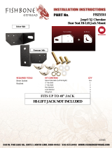
INSTALLATION INSTRUCTIONS
For ma Control and Floor Bracket
Model No. 250
Jeep Cherokee Wagon/Wagoneer
'84 & Later
No. 10 x 1" SCREW (2)
No. 10 LOCK WASHER (2)
LOCK SPOOL - Should be engaged when
mounted plow is not in use.
No.8 x 55" SCREWS (4)
ADJUSTMENT
PIVOT
FLOOR BRACKET 56079
RUBBER BOOT 56043
No. 10 x 33"TAPPING SCREWS (3)
90661
o ~--.(9'No. 10 x1" SCREW (2)
~ 0 No. 10 lOCK WASHER (4)
~ FlOORBRACKET
/' / STOOL 60758
No. 10 x 1 %" SCREW (2)
/" No. 10 x 111" SCREW (2)
No. 10 LOCK WASHER (2)
1. Temporarily assemble Floor Bracket to Floor Bracket Stool using three (3) No. 10 x ¥a" long hex head tapping screws. With
passenger seat in forward position, place floor bracket and stool assembly as shown to clear front of seat. Check under Stool hole
locations for wires or other interference before drillng two (2) 9/64" diameter holes into floor using the Stool as a templet.
Secure Stool to floor using two (2) No. 10 x 1%" sheet metal screws and lock washers. Remove Floor Bracket from Stool and dril
two (2) 9/64" diameter holes into tunnel using the Stool as a templet. Secure Stool to tunnel with two (2) No.1 0 x 1" sheet metal
screws and lock washers.
2. Assemble the floor bracket to floor bracket stool using three (3) No.1 0 x %" long hex head tapping screws. Place rubbr boot onto
body of floor bracket.
3. Pass control cables of ma Control through holes driled in the passenger side of firewalL. Dril per hydraulic system instructions.
4. Assemble the ma Control in desired position to the floor bracket using four (4) No.8 x %" long hex head screws.
5. Rotate Floor Bracket and Control to desired poSition and tighten three (3) mounting screws. Slide rubber bot down to cover
attaching flange screws. 13322-8701
-3-

INSTALLATION INSTRUCTIONS
FOR 59700 BLADE GUIDE ASSEMBLY
The following instructions simply outline the attachment of this blade guide assembly
Step 1.
Step 2.
Lower blade to ground level
If hole is not pre-drilled, drill one 11,1 32" hole, 1-3/16" down and 1 "out on the outside
rib of the blade. See diagram below
Insert pointed end of clamp. into corl of guide Attach guide to rib using top hole of clamp.
Secure assembly using supplied 5/16" x 1" bolt and locknut. Tighten until guide will
stand alone perpendicular to road surface.
If hole is not pre-drilled, use lower hole of clamp as locator, nrill bottom hole 11/32".
Bolt lower hole in place Finish securing top bolt
Attach other side following above steps.
2
3
4
Part No
59697
59694
59696
59691
59946
Quan.
2
1
1
1
2
4
4
Description
Blade Guide Rod. S-Hook & Flag
Flag
S-Hook
Blade Guide Rod
Clamp
Capscrew - 5 16"-18x 1"Gr.2
Locknut - 5. 16"-18 Nylon Insert
~ ;;.
0':8
.~
Step 3.
Step 4.
Step 5
Step 6.
Pictorial view supplled below Remember to use standard methods and practices in attaching
blade guides including wearrng safety glasses during drilling.
PARTS LIST
59700 - BLADE GUIDE ASSEMBLY
Item
1
5
6
7
i 309-7911
The following are registered( or unregistered™ Trade Marks of Douglas Dynamics, Inc.
WESTERN~ ISARMATIC(I Hydra-TurnCI Roll-Action™
Western reserves the right under its Product Improvement Policy to change construction or design details and furnish equipment when so altered without
reference to illustrations or specifications used herein.
Printed in U.S.A -4
/