Page is loading ...

10-8312
Advanced Engine Management Inc.
2205 126th Street, Unit A
Hawthorne, CA 90280
Phone: 310.484.2322
http://www.aempower.com
Equipped with AEM DRYFLOW Filter
No oil required!
Kit Part Number: 21-8312
2007 Jeep Wrangler 3.8L V6 CARB EO # Pending
Brute Force Intake Systems that are pending an Executive Order number (EO#) relating to exemptions under Section 27156 of the Vehicle Code from the California Air Resource
Board (CARB) are for off-road use only in California, which may never be used on public highways.
© 2006, Advanced Engine Management, Inc. AEM is a registered trademark of Advanced Engine Management, Inc. All rights reserved.

10-8312
Instructions 10-8312 Page 2 of 9 9.27.2006 Rev A

10-8312
Instructions 10-8312 Page 3 of 9 9.27.2006 Rev A
Bill of Materials
QTY PART DESCRIPTION PART # QTY PART DESCRIPTION PART #
1 Intake Pipe 2-83121 2 Washer ,8mm 559960
1 Heat Shield 20-8312 18 Rubber Edge Trim 8-111
1 Instructions 10-8312 16
Sponge Rubber
Gasket 8-119
2 Spacers 2-658 2 AEM Vinyl Decal 10-922Y
2 Washer, 1/4 X 1-1/4
Fender 1-3027 1
Hose, Adapter
2.50/3.0" X3" 5-253
2 Washer, 1/4 SAE Flat 1-3028 1 #48 Hose Clamp 103-BLO-4820
2 Bolt, Hex 1/4-20 X 1
3/4 1-2072 1 #52 Hose Clamp 103-BLO-5220
2 Nut, 1/4-20 1-2073 1 #44 Hose Clamp 103-BLO-4420
1 Grommet, 7/16" 784632 1 3.00”X9.00” Air Filter 21-2039D
1 Hose Clamp, 1" 99024.032 2 8mm Serrated Nut 444.460.08
1 8mm Rubber Mount 1228560

10-8312
Instructions 10-8312 Page 4 of 9 9.27.2006 Rev A
1. Preparing Vehicle
a) Make sure vehicle is parked on a level surface.
b) Set parking brake.
c) If engine has run in the past two hours let it cool down
2. Removal of Stock System
a) This is the stock intake of
the Jeep Wrangler. b) Loosen the hose clamp
located at the throttle body.
c) Release the wiring
harness from the IAT sensor
located on the intake tube.
d) Pull off the stock breather
hose from the air box lid.
Recommended Tools:
5/16” Socket
10 mm Socket
5/16” Nut Driver
Extension
Ratchet
10mm Wrench
Installation Time: 2 hours

10-8312
Instructions 10-8312 Page 5 of 9 9.27.2006 Rev A
e) Unclasp the two clips
securing the air box lid. f) Slide the intake tube off of
the throttle body and take off
the complete assembly.
This is the intake tube and
air filter lid after removal
from vehicle. Be sure to
remove the IAT sensor from
the intake tube and keep it in
a safe place.
g) Remove the stock air
filter. Then pull the lower
part of the air box straight up
out of the vehicle.
h) Remove the three stock
grommets.
j) Engine bay after the stock
intake has been removed..
i) Remove the self tapping
screw securing the fan
shroud. Keep this screw for
later use.

10-8312
Instructions 10-8312 Page 6 of 9 9.27.2006 Rev A
f) Secure the tab on the
heatshield using the stock
screw removed in step 2(j)
3. Installation of Brute Force Intake
a) When installing the intake system, DO NOT completely tighten the hose clamps or mounting tab hardware until instructed to do so.
b) Prepare the supplied
bolts with the small washers.
d) Insert the prepared bolts
and washers through the
heatshield and then guide
the bolts through the
spacers in the vehicle.
c) Place the two supplied
spacers in the same location
you removed the stock
grommets from.
e) Use the larger supplied
washers and supplied nuts
to secure the heatshield.
Refer to diagram to view the
assembly.
g) Secure the rubber mount
to heatshield using the
supplied washer and nut.
Put the rubber gasket on the
edge of the heathsield, and
use the rubber edge trim on
the pipe opening.
Rubber
Gasket

10-8312
Instructions 10-8312 Page 7 of 9 9.27.2006 Rev A
h) Put the reducing coupler
on the throttle body. i) Slide the pipe into the
coupler and put the hose
clamps loosely around the
coupler ends. (#44 hose
clamp on the throttle body
and the #48 hose clamp on
the pipe).
j) Align the bracket to the
rubber mount installed on
the heatshield then loosely
secure the bracket to the
rubber mount.
k) Install grommet in pipe
and then insert the IAT
sensor removed from the
stock intake tube into the
grommet in the pipe. Then,
re-connect the wiring
harness to the IAT sensor.
l) Attach the stock breather
hose to the nipple on the
intake pipe and secure with
the supplied hose clamp.
m) Finally, install the
Dryflow Filter on the intake
tube and secure it with the
supplied #52 hose Clamp.

10-8312
Instructions 10-8312 Page 8 of 9 9.27.2006 Rev A
Before After
Note: Be sure to remove the plastic covering on the AEM Brute Force
Emblem

10-8312
Instructions 10-8312 Page 9 of 9 9.27.2006 Rev A
For technical inquiries
e-mail us at
tech@aempower.com
or
call us at
310.484.2322 Option #3
4. Re-assemble Vehicle
a) Position the inlet pipes for best fitment. Be sure that the pipes or any other components do not contact any part of the
vehicle. Tighten the rubber mount, all bolts and hose clamps.
b) Check for proper hood clearance. Re-adjust pipes if necessary and retighten them. Tighten radiator cap.
c) Inspect the engine bay for any loose tools and check that all fasteners that were moved or removed are properly tight.
d) Start engine. Let car idle for 3 minutes. Perform a final inspection before driving the vehicle.
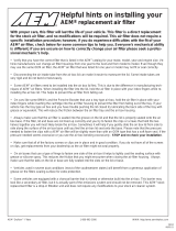
5. Service and Maintenance
a) It is recommended that you service your AEM Dryflow filter every 20,000 miles for optimum performance. Use AEM
Dryflow cleaning kit part # 21-110.
b) Use aluminum polish to clean your polished AEM Brute Force intake pipe.
c) Use window cleaner to clean your powder coated AEM Brute Force intake pipe. (NOTE: DO NOT USE Aluminum
polish on a powder coated AEM BRUTE FORCE intake pipe)
12 MONTH LIMITED WARRANTY
AEM warrants that its intake systems will last for the life of your vehicle. AEM will not honor this warranty due to mechanical
damage (i.e. improper installation or fitment), damage from misuse, accidents or flying debris. AEM will not warrant its powder coating if the
finish has been cleaned with a hydrocarbon-based solvent. The powder coating should only be cleaned with a mild soap and water solution.
Proof of purchase of both the vehicle and AEM intake system is required for redemption of a warranty claim.
/