Page is loading ...

1
GB
ACTIVE WHEELCHAIR
OPERATING MANUAL
GB
D–GB–F–I–E–NL
PROFI 3
Model 2.871
Model 2.875-S
OPERATING MANUAL
WHEELCHAIRS AND REHABILITATION
EQUIPMENT
Model 2.871
Model 2.875

2
TABLE OF CONTENTS
Introduction 3
Acceptance 3
Assembly 3
Specifications / Utilization 4
Driving behavior 4
Safety instructions 4
Driving training 4
General overview 5
Brakes 5
Legrests 6
Leg retainer 6
Armrests 6
Mudguard 7
Backrest 7
Backrest belt 8
Seat belt 8
Drive wheels 8
Centre of gravity 9
Wheel camber 9
Toe-in 9
Handrims 10
Hand and spoke guard 10
Steering wheels 10
Front seat-height 10
Seat tilt 11
Steering head adjustment 11
Push handle 11
Service 12
Maintenance 12
Cleaning 12
Spare parts 12
Maintenance instructions 12
Service 12
Maintenance instructions 12
Special valve 13
Loading into the transport vehicle 14
Technical specifications 14
Notes 18
Guarantee 19
Guarantee note 19
Illustration section of the operating manual 21

3
GB
ACCEPTANCE
All MEYRA wheelchairs are tested in our
factory for fault-free operation, and are
packed in special boxes.
However, we request that you check the
vehicle for possible transport damage
immediately on receipt – preferably in
the presence of the carrier.
Please arrange the following if you be-
lieve damage occurred during trans-
port:
a) Draw up a DAMAGE REPORT – the
carrier is required to do this.
b) Draw up a LETTER OF SUBROGA-
TION – you assign to the supplier all
claims resulting from this damage.
c) Send back the BILL OF LADING, the
DAMAGE REPORT and the LETTER
OF SUBROGATION to us.
We are unable to accept any claims for
compensation if you fail to observe
these instructions or notify us of damage
after the goods have been accepted.
INTRODUCTION
With the PROFI 3 model 2.871 and
model 2.875-S from MEYRA, you own
a highly sophisticated sport wheelchair
which can be adapted to your personal
needs.
The technical innovations which our engi-
neers have incorporated in co-operation
with athletes who have practical experi-
ence make this wheelchair an ideal
partner for demanding wheelchair ath-
letes.
This operating manual will give you all
the information your require – clearly
written and with illustrations.
This operating manual is applicable for
the PROFI 3 model 2.871 and the
model 2.875-S with all equipment var-
iants and their accessories. It will there-
fore contain chapters that do not apply
to your model.
Be sure to read and under-
stand this operating manual
and the brochure “Safety infor-
mation - Mechanical wheel-
chairs” before your first drive.
Pictures and graphic illustra-
tions are contained in the ap-
pended illustration part.
Note!
The components shown in the figures
are not always identical with your
wheelchair model. The position and
the use of the parts to be operated
can be transferred to your model. Al-
ways check that components are fixed
correctly after assembly as well as
after any adjustment or modification.
ASSEMBLY
Your PROFI 3 will have been assem-
bled and adapted to your personal
needs when it is handed over to you by
the specialist workshop.
Assembly
After transportation, carry out the fol-
lowing before use of the wheelchair:
Availability
– Take possession of the wheelchair
disassembled for transportation.
Attaching the drive wheels
(Fig.1)
– Press in the stop button (10) in the
centre of the wheel hub.
– Attaching drive wheel. – Push on the
drive wheel until the end stop of the
axle mount is reached.
Note!
The stop bolt must protrude a few mil-
limeters from the wheel nut after let-
ting go. The drive wheel is then se-
cured in position.
Unfolding the backrest
(Fig.2)
– Swivel the backrest upwards until the
locking bolts click audibly in place.
– Check the locking mechanism.
Fitting the clothing guards or
unfolding of armrests
(Fig.2+3)
– Unfold armrests or insert the clothing
guards into their mounts, from
above, up to the end stop.
Placing seat cushion in place
– Place seat cushion according to the
position of the Velcro strips and press
to fix. – The Velcro strips prevent the
seat cushion from slipping.

4
SPECIFICATIONS/ UTILI-
ZATION
Due to the numerous infinitely-variable
adjustment possibilities of the PROFI 3,
this wheelchair also offers persons with
a higher level of disability the necessary
safety during sport usage.
As a special development for athletics
and normal sport, the PROFI 3 is a reli-
able maneuverable partner that will of-
fer you all its advantages and thus much
pleasure in use, even during its normal
use as an active wheelchair.
It serves exclusively for the transporta-
tion of a person on the seat and not as
ladder or as a means of pulling or trans-
porting items, or similar.
Note:
Parking brakes are not permitted for
some types of indoor sports.
The pressure brakes are therefore re-
movable for a quick change from ac-
tive wheelchair to sport wheelchair.
The PROFI 3 is designed for firm and
level surfaces. For your own safety, do
not drive onto soft, uneven surfaces.
DRIVING BEHAVIOR
Allow your wheelchair to be adapted to
your own personal needs, only then will
your PROFI 3 offer you an optimum driv-
ing behaviour.
Observe the sections
Driving training
and
Safety Notes
.
SAFETY INSTRUCTIONS
You must observe the following instruc-
tions, they serve for your own safety.
– Read and observe the
Safety Notes
– Mechanical Wheelchairs
bro-
chure.
– The wheelchair is designed and ap-
proved for use by only one person.
– Do not rest your legs on furniture or
other items. – Risk of overturning
when leaning backwards.
– Do not throw or drop parts belong-
ing to the wheelchair! – Remov-
able parts, like clothing guards and
drive wheels, must be correctly han-
dled. To guarantee their function.
– A passive illumination must be availa-
ble when participating in public road
traffic!
– Secure your wheelchair against unin-
tentional use – especially by chil-
dren.
DRIVING TRAINING
The safe use of your wheelchair in-
cludes not only the correct adjustment of
the PROFI 3 to your personal needs (
see
information on adjustment options /
wheelchair adaptation
) but also an in-
tensive driving training.
Observe the
General Safety Notes
sec-
tion and the
Driving Training
section in
the
Safety Notes – Mechanical
Wheelchairs
brochure.
Obtain instruction from:
– your authorised dealer,
– the trainer of your wheelchair sport
association,
– the sport department of MEYRA.
Do this by contacting the manager of our
sport department, you will then gain the
maximum benefit from your PROFI 3.

5
GB
GENERAL OVERVIEW
The model shown in Fig. 4 and 5 is the
standard version. All deviations are
specified separately in this operating
manual.
No. Designation
1 Backrest tube
2 Backrest
3 Clothing guard / armrest
4 seat belt / seat cushion
5 Lower leg strap
6 Legrest
7 Steering wheel
8 Drive wheel
9 Handrims
10 Stop button of the axle
11 Pressure brake
12 Steering head
13 Pull rope for backrest
14 Handle
BRAKES
The PROFI 3 can be upgraded with a
removable pressure brake, code 305
(Fig.6). It works directly on the tyres.
Benefits:
– controlled braking of the driving
speed (service brake)
– securing the wheelchair against acci-
dental rolling (parking brake).
Note:
The wheel cambering must be indicat-
ed when subsequently ordering a
pressure brake.
Please observe the
Maintenance In-
structions
as well as instructions in the
chapter “
General Safety Information”
and “Brakes
” in the brochure
“Safety
information – Mechanical wheel-
chairs”
!
Service brakes
Press evenly both brake levers (11) only
slightly forward for a controlled and di-
rection-stable braking of the wheelchair
(service brakes).
Parking brakes
You lock the brakes (parking brakes) by
pressing the brake levers forward until
the end stop is reached. – The wheel-
chair can then not be pushed.
Benefits:
– Controlled braking of the driving
speed (service brake).
– Secures the wheelchair against acci-
dental rolling.
– Adaptation to the sport rule (no
brakes) by way of removable
brakes, code 305.
Locking the pressure brakes
Push both brake levers (11) forward as
far as they will go (Fig. 7).
Note!
If only one brake is applied when the
wheelchair is driving down an incline,
the free-running wheel will continue
moving around the locked wheel.
Depending on the gradient of the
road, this can lead to the wheelchair
overturning to the side.
Releasing the pressure brakes
Pull both brake levers [11] back,
(Fig.6).
Adjusting the pressure brakes
– Loosen the clamping lever.
– Pre-set the pressure brake – Slide the
brake bolt of the non-activated pres-
sure brake to a point approx. 15mm
to 20mm in front of the drive wheel
(8).
– Tighten the clamping lever.
Note!
It should not be possible to push the
wheelchair forward when both
brakes are locked.
The brake performance decreases
when the:
– tyre profile is worn
– tyre pressure is too low
– tyres are wet
– pressure brake is loose
– brake mechanism is defective.
Note:
You will find the values for the correct
air pressure for the wheelchair in the
Technical Specifications.
Defective pressure brakes
must be replaced!

6
ARMRESTS
Model 2.871
The choice of foldable or slide-action
side parts is dependent on the seat tilt:
armrest code 302 (Fig.2) for up to 8
cm tilt and
armrest code 303 for seat tilt of more
than 7 cm.
A readjustment of the armrests for the
proper closing of the Velcro fastening
after a change in the seat tilt is recom-
mendable.
Handling:
Tools
Phillips screwdriver
Engineer’s wrench WW* 8
– Fold side parts inwards (Fig.13).
– Slacken the adjustment screws (A,
Fig 13).
– Adapt armrest position. – Adjust the
side parts until the Velcro strips are
almost aligned.
– Tighten adjustment screws.
– Upright the side parts by folding them
outwards up to the end stop. – Side
parts will be held by the Velcro fas-
tener.
LEGRESTS
The legrests and the crash bar code
310 are height-adjustable by 60mm in
4 positions.
Benefits:
– Individual adjustment of the legrest to
the length of your lower leg
Height adjustment:
Tools:
Engineer’s wrench WW* 10
Hexagonal stud wrench WW* 4
– Undo screw connection (A, Fig.8).
– Slide leg supports to the desired po-
sition.
– Assemble the screw connection (A,
Fig.8).
Footrest code 310
The height adjustment of the footrest (B,
Fig.9) is infinitely variable, the crash bar
(C, Fig.9) is height adjustable by 60mm
in 4 positions.
Benefits:
– Individual adaptation of the legrest to
the length of your lower leg by way
of infinitely variable height adjust-
ment.
Handling:
Hexagonal stud wrench WW* 4
– Slacken the fastening screws (D,
Fig.10).
– Position footrest at the desired
height.
– tighten fastening screws.
Attention:
Avoid a strong pressure between
thighs and safety belt edge. – Blood
circulation problems!
LEG RETAINER
The leg retainer code 316 (Fig.11) is
mounted by way of a clamp on the front
frame.
Benefits:
– Stabilisation of the leg position.
– Infinitely variable adaptation to the
personal needs of the user.
Handling:
Tools
Hexagonal stud wrench WW*6
– Loosen adjustment screw (A, Fig.
11).
– Individually position the leg retainer
by rotating and/or sliding.
– Tighten adjustment screw.
WW* = Wrench width [mm]

7
GB
MUDGUARD
Model 2.875-S
The removable clothing guards running
parallel to the wheel circumference
must be adapted to the chosen wheel
position (Fig.14).
Benefits:
– Lateral support for body
– Clothes protected against soiling by
the wheels.
– Wind protection.
Note!
Do not drive without the cloth-
ing guards!
Do not lift your wheelchair via
the clothing guards!
The distance between the driving
wheel and the mudguard should be as
small as possible, approx. 1 cm.
Removal of clothing guards
The clothing guards must be removed
before folding over the backrest.
– Pull the clothing guards upwards out
of the guides (Fig.15).
Fitting the clothing guards
– Insert the clothing guards into their
guides from above and press down
(Fig.14).
Adapting the clothes guard
Height adjustment (Fig.16):
The height adjustment of the clothing
guard is infinitely variable.
Tools:
1 x open-end wrench SW* 4-5/32
1x Phillips screw driver
– Remove drive wheel (see
Drive
wheels
section).
– Slacken the adjustment screws (A). –
Slide the clothing guard slightly up-
wards.
– Fit drive wheel and then adapt cloth-
ing guard to the wheel circumfer-
ence.
– Tighten adjustment screws (A). – First
remove drive wheel.
Horizontal adjustment (Fig.17):
The clothing guard is horizontally adjust-
able by two positions, each 2cm.
Tools:
1 x open-end wrench SW* 4-5/32
– Remove drive wheel (see
Drive
wheels
section).
– Remove retaining screws (B) of the
stabiliser bars (C).
– Identically adjust both stabiliser bars
(C) as desired.
– Assemble screw connection (B).
– Fit drive wheel and then adapt cloth-
ing guard to the wheel circumfer-
ence.
– Tighten screw connections (B). – First
remove drive wheel.
WW* = Wrench width [mm]
BACKREST
The backrest can be folded and its an-
gle can be adjusted by approx. ± 10°
(Fig.19).
Benefits:
– Relief for the spinal column.
– Relaxed sitting position.
– Smaller transport dimensions.
Folding:
– Remove seat cushion.
– Remove clothing guards (Fig.15) or
fold side parts inwards (Fig.13).
– Unlatch the backrest. – Pull or press
pull rope (Fig.20) downwards.
– Fold backrest onto the seat (Fig.19).
– Press the backrest forwards over
the latching point.
Unfolding:
– To unfold, pull the handle with a jerk
to the rear up to the end stop. – The
thrust bolts must audibly click into
place.
– Fit the clothing guards or unfold the
side parts:
Remark
The greasing of the thrust bolts is rec-
ommended for an easier latching of
the backrest.

8
BACKREST BACKREST BELT
The backrest belt slackness can be ad-
justed to the personal needs of the user
by way of the Velcro fastener (Fig.23
and 24).
Backrest height adjustment
– Pull the backrest belt off the Velcro
strips and wrap it forwards.
– Remove screw connection (D,
Fig.23).
– Slide the adjustment tubes to the de-
sired hole position.
– Assemble screw connection (D,
Fig.23).
– Re-fasten the backrest belt.
SEAT BELT
The seat belt slackness can be adjusted
to the personal needs of the user by way
of the Velcro fasteners (Fig.25).
Angle adjustment
The angle adjustment occurs after the
locking pieces (C, Fig.22) have been
undone.
Tools:
1x engineer’s wrench WW* 13 and
17
– Remove clothing guards.
– Undo the lock nuts (A, Fig.21) of the
end stop screws in the frame tube.
– Screw in end stop screws (B, Fig.21)
if necessary.
– Undo the lateral locking pieces (C,
Fig.21).
– Place backrest in the new position.
– Tighten the locking pieces (C,
Fig.22). – The key faces of the lock-
ing pieces must be positioned almost
parallel to the driving surface (C,
Fig.21) in order to ensure a latching
via the facing angles.
– Screw out the end stop screws (A,
Fig.21) up to the end stop.
– Tighten the locking nuts (B, Fig.21).
– Fit the clothing guards.
DRIVE WHEELS
Note:
You will find the air pressure values
for the tyres for your wheelchair in the
Technical Specifications or the infor-
mation given for both sides of the
wheels.
Linchpin
The driving wheels (8) can be removed
and re-assembled without any tools.
Benefits:
– Simple and quick loading away of
the wheelchair even in small cars.
– Quick and simple replacement of
driving wheels with different tyres.
Handling:
– Push in the stop button [10] in the
centre of the wheel hub (Fig.26) and
– Remove or attach drive wheel [8].
Note!
After installing the drive wheel, the
stop button must protrude a few mil-
limeters from the wheel nut. – The
driving wheel is secured in position.
The stop bolt must be kept clean. A
functional fault may occur in the case
of contamination due to sand or earth
or in the event of freezing of moist
cold air.
Always carry out a tensile test after
each assembly!
WW* = Wrench width [mm]

9
GB
CENTRE OF GRAVITY
The adjustment should be car-
ried out by the specialist
dealer!
The centre of gravity is infinitely variable
by way of axle tube displacement.
Note!
The overturning risk increases
with a reduction in the axle
separation distance (Forward
displacement of the axle tube)!
The axle tube must be displaced in a
parallel manner for a perfect driving
behaviour. The separation distance
between axle tube and backrest tube
(Fig.27) must be the same on both
sides.
Handling:
Tools
Hexagonal stud wrench WW* 4
– Slacken the adjustment screws (A,
Fig. 28) of the axle tube.
– Slide the axle tube parallel to the
desired separation distance
(Fig.29).
WW* = Wrench width [mm]
TOE-IN
The adjustment should be car-
ried out by the specialist
dealer!
The toe-in can be adjusted by rotating
the mount adapter (B, Fig.31) for the
axle.
Handling:
Tools
Engineer’s wrench WW* 10 and 22
Hexagonal stud wrench WW* 4
– Slightly slacken the adjustment screw
(A, Fig.31) of the tube clamp. – It
should be just possible to turn the
axle mount adapter with the open-
end spanner.
Set toe-in with attached drive wheels:
– Optically align drive wheels parallel
to the frame. – Do this by rotating the
axle mount adapters (B, Fig.31) in
the appropriate direction.
Fine adjustment:
– Adjust for equal front spacing be-
tween drive wheel and the frame
tube on both sides. – The spacing is
to be determined with, for example,
a ruler (Fig. 32).
Remark
The above only ensures that the drive
wheels are positioned equally to the
frame.
– Measure the front and rear spacing
between the drive wheels at the
same height (Fig.33).
WHEEL CAMBER
The adjustment should be car-
ried out by the specialist
dealer!
The wheel camber (Fig.30) can be set
to 1° or 3° by way of different axle
mount adapters.
Handling:
Tools
Hexagonal stud wrench WW* 3
– Detaching drive wheel. – Do this by
pressing in the stop knob at the centre
of the wheel and pulling off the
wheel.
– Slacken the adjustment screw (A,
Fig.31) of the tube clamp.
– Pull off the axle mount adapter.
– Insert the axle mount adapter with
the desired wheel camber in the
mounting tube.
– Lightly tighten the adjustment screw
(A).
– Attach the drive wheel (see
axle
).
– Adjust toe-in (see
Toe-in
).
– Convert other side accordingly.
Note:
When ordering different axle mount
adapters for a wheelchair equipped
with pressure brakes it is necessary to
order the required spacers at the
same time.

10
STEERING WHEELS
The steering wheels can be exchanged
without difficulty.
Handling:
Tools
2x hexagonal stud wrench WW* 4
– Dismantle steering wheel screw con-
nection (A, Fig.36).
Note:
Please note the position of the washer
and the spacer before disassembling
the screw connection!
– Replace steering wheel, if necessary
or re-position to suit your require-
ments.
– Assemble steering wheel screw con-
nection
Note!
The skater wheels code 446 are pri-
marily for use indoors and on firm lev-
el surfaces.
The crossing of uneven surfaces,
grooves or edges, etc. can lead to a
full-braking. – Accident risk, user
could fall out of the wheelchair.
FRONT SEAT-HEIGHT
The adjustment should be car-
ried out by the specialist
dealer!
The seat tilt is infinitely variable by con-
stant chassis geometry.
HANDRIM
All handrims [9] are designed for a dis-
tance to the driving wheel [8] of 15 mm
(standard setting) and 25 mm (Fig.34).
Replacement of handrims or modifica-
tion of handrim distances should always
be carried out by your authorized spe-
cialist workshop.
Please observe the chapter
“Handrims” in your brochure “Safety
Notes -– Mechanical Wheelchairs”!
HAND AND SPOKE
GUARD
The hand and spoke guard prevents inju-
ries to the hands occurring by jamming
in the turning spokes of the wheels, as
well as damage to the spokes.
Handling:
Tools 2x slot screw drivers
– Dismantle clamping screws (A,
Fig.35) of the disc to be replaced.
– Replace defective disc.
– Position new disc (see note).
– Assemble clamping screws (A).
Note:
Gently press the hand and spoke
guard discs through the appropriate
grip wheels.
The notches on the circumference of
the discs lie above the handrim brack-
ets!
All three bores of the discs should be
positioned between two crossing
spokes!
Note:
If toe-in adjustment equipment is not
available, use two items of identical
height (e.g. bottles as in Fig.33) in or-
der to measure the spacings at the same
height.
– Readjust on each side for a ¼ of the
difference between the front and
rear measured drive wheel spacing.
• Measure the front spacing from drive
wheel to frame tube (Fig.32).
• Rotate the axle mount adapter in the
appropriate direction to readjust for
a ¼ of the difference on both sides.
• Compare the new spacing on both
sides.
Note:
The toe-in of both sides must be identi-
cal. Different toe-in settings will cause
your wheelchair to roll to the left or right
of a straight line.
– Tighten the adjustment screw (A,
Fig.31) of the tube clamp.
TOE-IN
WW* = Wrench width [mm]

11
GB
PUSH HANDLE
The insertion tubes (Fig.40) can be re-
placed with push handles (Fig.41).
Fitting push handles
Tools:
Hexagonal stud wrench WW* 4–5/
32
– Pull the backrest belt off the Velcro
strips and wrap it forwards.
– Remove screw connection (A,
Fig.40).
– Remove the backrest strap.
– Remove screw connection (B,
Fig.40). – Keep hold of the insertion
tube as it will otherwise slide into the
backrest tube.
– Replace insertion tube with push han-
dle (or vice versa) and position it at
the desired hole location.
– Assemble screw connection (B,
Fig.41).
– Re-fit backrest strap.
– Assemble screw connection (A,
Fig.41).
– Re-fasten the backrest belt.
STEERING HEAD AD-
JUSTMENT
The adjustment should be car-
ried out by the specialist
dealer!
The steering heads (A, Fig.39) for bear-
ing support of the steering wheel forks
can be adjusted for an optimum driving
behaviour 90° to the driving surface by
way of the respective eccentric screw
(B., Fig.39).
Important information:
Eccentric screws to adjust the steering
head have to be secured with soluble
Loctite glue after every third adjust-
ment. – Remove grease and glue re-
mainders from the flights of the eccen-
tric screws or use new eccentric
screws alternatively.
SEAT TILT
The adjustment should be car-
ried out by the specialist
dealer!
The seat tilt is infinitely variable by con-
stant chassis geometry.
Benefits:
– High sitting stability by way of
wedge-shaped seat position via ad-
justable seat tilt.
Handling:
Tools
Hexagonal stud wrench WW* 4+5
Engineer’s wrench WW* 10
– Fold armrests onto the seat.
– Slacken the screw connection of the
rear seat-strut mount (A, Fig.37).
– Slacken the screws of the clamping
guides (B, Fig.38).
– Adjustment of seat tilt. – Position the
backrest tubes for the desired rear
seat-height.
Note:
The adjustment should be made so
that the backrest tubes protruding from
the clamping guides have the same
length.
– Tighten the screws (B, Fig.38) of the
clamping guides.
– Tighten the screw connection of the
rear seat-strut mount (A, Fig.37).
WW* = Wrench width [mm]

12
SERVICE
Maintenance
Like any other technical product, your
Profi 3
also needs to be maintained.
The following maintenance instructions
describe, in table form, the work that
needs to be carried out so that you will
be able to fully enjoy the advantages of
your wheelchair (quiet running, low roll-
ing resistance) even after a long period
of use.
Care
Seat and backrest cover:
Clean the covers with warm water. In
the case of stubborn soiling, the fabric
can be washed with a standard washing
powder for delicate fabrics. Spots can
be removed with a sponge or a soft
brush.
Note:
Do not use aggressive cleaning agents
e.g. solvents, or hard brushes etc.
Rinse with clear water and let get dry.
Plastic parts:
The foot plates, or similar, consist of
high-quality plastic parts. Take care of
these by means of standard plastics
cleaning agents. Always observe the
specific product information.
Finish:
The high quality finish ensures an opti-
mum of protection against corrosion. If
the surface finish is damaged by scratch-
es or similar, touch it up with a varnish
pen available from us. Occasional ap-
plication of a light cover of oil to all
moving parts (see also Maintenance In-
structions) will ensure that your wheel-
chair will give you many years of serv-
ice.
Spare parts
Only use ORIGINAL MEYRA
spareparts.
The wheel camber must be indicated
when ordering a pressure brake.
Repairs
If any repairs are required, please con-
tact your specialist workshop. Personnel
there are well trained to carry out the
work required.
Customer Service
Should you have any enquiries or need
any assistance, please contact your lo-
cal MEYRA specialized dealer, who has
been trained in our factory in accord-
ance with our guidelines and who can
offer advice, customer service and re-
pairs. We have a dealer network of
approx. 1.500 dealers in germany. In
this way all wishes can be fulfilled.
MAINTENANCE IN-
STRUCTIONS
Before starting out
1. Test brakes for faultless op-
eration
Move the brake release lever (11) to
drive mode. It should now be impossi-
ble to push the wheelchair. If this is not
the case, have the magnetic brakes re-
paired by an authorized specialist work-
shop.
Remark:
Carry out check yourself or with a help-
er (see
Brakes
section in
Safety Notes
brochure).
2. Check pressure brakes for
wear.
Move brake lever to the side.
Remark:
Carry out test yourself or with a helper.
If you notice any increasing slackness on
the brake lever take the wheelchair to
your authorized specialist workshop im-
mediately for repairs. – Danger of acci-
dents!
3. Check tyre pressures.
Full tyre pressure – drive wheel
Standard pneumatic tyres = 2.5 bar
Ultra smooth running tyres = 6 bar
High-pressure tyres = 8 bar
Indoor sport = 11 bar
Remark:
Do it yourself or with the aid of a helper
Use a tyre gauge or, if you do not have
one, use the "thumb pressure method"
(see safety instructions in the section enti-
tled "Tyres".

13
GB
4. Check tyre profiles, axle
tube, frame tubes for cracks or
other damage
– Minimum tread = 1 mm
– Do not repair or continue to use de-
fective tubes. – Danger of accidents!
Remark:
Carry out visual check yourself.
Use an authorised specialist workshop
for renewal//repair in the event of
worn tyre profile, or damage to the
tyre, axle tube or frame tube.
Every 8 weeks
(depending on frequency of use)
Check all screw connections for
secure fit
– Carry out test yourself or with a help-
er.
Lubricate the following compo-
nents with a few drops of oil
Do it yourself or with the aid of a helper
Components must be free from used oil
residues before lubrication. Please en-
sure that excess oil does not contami-
nate the environment (e.g. your clothing)
– Brake lever bearings
– Linchpin
– Thrust bolt of the backrest latch.
– Stub axle for removable drive
wheels
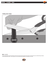
SPECIAL VALVE
The drive wheels (14) are equipped
with a special valve (Fig.42) in the case
of tyre pressure of up to 11 bar.
Use the following for an easier pumping
up of the tyres:
– a foot pump for racing cycles (with
manometer) or
– the manual compressor (can also be
used for the car valve of normal tyres
when adapter is used).
Observe
Brakes
section in
Safety
Notes
brochure!
Note:
You can obtain a 'car valve to special
valve' adapter (order no. 206 125
600) from your specialist dealer.
Use of special valve:
– Prevent a rolling of the wheelchair.
– Unscrew valve cap.
– Slacken the knurled nut (Fig.43).
– Push valve shoe of foot pump or com-
pressor (not included in the scope of
supply) onto the valve and secure by
folding over the clamping lever, if
available.
Use of car valve:
Drive wheels with standard or fail-safe
tyres (code 486 & 487) are fitted with
car valves.
– Prevent a rolling of the wheelchair.
– Unscrew valve cap.
– Push the valve shoe of the com-
pressed air device for car tyres onto
the valve and secure by folding over
the clamping lever or
– Screw adapter (car valve to special
valve) onto the valve.
– Push valve shoe of foot pump/com-
pressor (not included in scope of sup-
ply) onto the valve and secure by
folding over clamping lever (when
available).
MAINTENANCE IN-
STRUCTIONS
Every 6 months
(depending on frequency of use)
Please check:
– Cleanness. – See Care
– General condition. – See Repairs
– Secure screw connections. – Do it
yourself or with the aid of a helper
– Functioning of the steering wheels. –
In the event of rolling resistance, you
(or a helper) should remove the stee-
ring wheels ( see 'Steering wheels'
section) and clean the bearings.

14
LOADING INTO THE
TRANSPORT VEHICLE
Attention:
For the transport in vehicles, you must
leave the PROFI 3 and occupy a suita-
ble seat in the vehicle. It is forbidden
to remain seated in the PROFI 3 dur-
ing vehicle transportation. – Accidents
produce forces which the PROFI 3 is
not designed to handle and therefore
seriously endanger you as occupant.
Before transporting the wheelchair,
ask your car dealer how to secure it
without risk to the existing fixtures or
other safety fittings!
Suitable fixing points can usually be
found in the car and in the vehicle
operating manual.
Assuming that the PROFI 3 is located in
the transport vehicle, you or a helper
should carry out the following:
– Operate parking brakes.
– Stow any parts removed from the
PROFI 3 safely and protectively.
– Remove bags, walking sticks and oth-
er items not belonging to the wheel-
chair and stow these safely.
– Secure the wheelchair by way of
elasticated straps.
Note!
The elastic straps are only to be se-
cured to the appropriate fastening
points of the vehicle and the frame of
the PROFI 3 (Fig.45+46)!
TECHNICAL DATA
Tyre filling pressure:
The following pressure values can be
taken as standard values:
Driving wheel:
Code 486
Standard = 4.0 bar
Code 488
Ultra smooth running = 6.0 bar
Code 496
High pressure = 8.0 bar
Code 485
Indoor sport =11.0 bar
Always observe the maximum tyre fill
pressure indicated on the tyre cover!
The product conforms with the
EC Directive 93/42/EEC
(MDD) for medical products

15
GB
* = Attention!
The maximum admissible passenger
weight reduces in accordance with
the number of additional mounted
parts and possible luggage.
The admissible passenger
(person) weight is calculated
on the basis of:
maximum passenger weight (Table
1)
– actual weight
= admissible weight for luggage or
mounted parts.
I.e., the passenger and luggage may
not weigh more than the specified
maximum passenger weight of 120
kg.
If the actual weight of the passenger
exceeds the calculated maximum user
(person) weight, reduce the weight of
additional mounted parts and lug-
gage.
If this is not possible, a more stable
version or another wheelchair model
must be used. Contact your MEYRA
specialist dealer in this respect.
TECHNICAL DATA
All length and height data in the table 1
relates to the Profi 3, model 2.871.
– Backrest height 38 cm
– Depth of seat 40 cm
– Frame length 58 cm
– Overall length 77 cm
– Drive wheel position standard (ap-
prox. 4 cm from backrest tube)
– Wheel size 24"
– Handrim distance 15 mm
Measuring tolerance ±1.5 mm.
The overall length is dependent on the
position of the infinitely adjustable axle
tube.
ledoM178.2ledom,3IFORP
]mc[)WS(htdiwtaes54/34/04/83/63/43/23
]seerged[rebmacleehW3811
]mc[htdiW62+WS43+WS14+WS
evirdehtneewtebhtdiwrewoL
]mc[sleehw
31+WS12+WS82+WS
]mc[htgnelemarF95:muidem46:gnol
]mc[tnorf,thgiehtaeS
74
)ebuttnuom-elxadetrevnocrof35(
89.xam]mc[thgieH89.xam
]mc[taesfohtpeD64/44/24/04/83/63
]gk[thgiewdedaolnU5.9morf
thgiewresu.xaM
]gk[egaggul.lcni
021
Table 1

16
TECHNICAL DATA
178.2ledom,elbatthgieh-taestnorF
-ehwgnireetS
mmniøle
,814edockrofgnireetS
mcnithgieh-taestnorf
914edockrofgnireetS ,
mcnithgieh-taestnorf
elohllirdts1elohllirddn2elohllirddr3elohllirdts1elohllirddn2elohllirddr3elohllirdht4
retaks08ø
leehw
849405.a.n152535
-dilos001ø
rebbur
94051515253545
-dilos521ø
rebbur
.a.n152525354555
578.2ledom,elbatthgieh-taestnorF
-ehwgnireetS
mmniøle
,814edockrofgnireetS
mcnithgieh-taestnorf
,914edockrofgnireetS
mcnithgieh-taestnorf
elohllirdts1elohllirddn2elohllirddr3elohllirdts1elohllirddn2elohllirddr3elohllirdht4
retaks08ø
leehw
849405.a.n152535
-dilos001ø
rebbur
94051515253545
-dilos521ø
rebbur
.a.n152525354555
atadthgieh-taesraeR
"42mc53otmc35morfelbairavyletinifni

17
GB
ledoM578.2ledom,S-3IFORP
]mc[)WS(htdiwtaes
04/83/63/43/23
54/34/
]seerged[rebmacleehW13
]mc[htdiW12+WS62+WS
evirdehtneewtebhtdiwrewoL
]mc[sleehw
8+WS31+WS
]mc[htgnelemarF95:muidem
]mc[tnorf,thgiehtaeS
74
tnuom-elxadetrevnocrof35(
)ebut
]mc[thgieH89.xam
]mc[taesfohtpeD44/24/04/83/63
]gk[thgiewdedaolnU5,9morf
thgiewresu.xaM
]gk[egaggul.lcni
021
* = Attention!
The maximum admissible passenger
weight reduces in accordance with
the number of additional mounted
parts and possible luggage.
The admissible passenger
(person) weight is calculated
on the basis of:
maximum passenger weight (Table
1)
– actual weight
= admissible weight for luggage or
mounted parts.
I.e., the passenger and luggage may
not weigh more than the specified
maximum passenger weight of 120
kg.
If the actual weight of the passenger
exceeds the calculated maximum user
(person) weight, reduce the weight of
additional mounted parts and lug-
gage.
If this is not possible, a more stable
version or another wheelchair model
must be used. Contact your MEYRA
specialist dealer in this respect.
TECHNICAL DATA
All length and height data in the table 2
relates to the PROFI 3, model 2.875-S:
– Backrest height 38 cm
– Depth of seat 40 cm
– Frame length 58 cm
– Overall length 77 cm
– Drive wheel position standard (ap-
prox. 4 cm from backrest tube)
– Wheel size 24"
– Handrim distance 15 mm
Measuring tolerance ±1.5 mm.
The overall length is dependent on the
position of the infinitely adjustable axle
tube.
Table 2

18
NOTES

19
GB
Vehicle ID no. (Fz-I-Nr.):
Company address:
Meyra-Ring 2
D-32689 Kalletal-
Kalldorf
MEYRA
Wilhelm Meyer GmbH & Co. KG
P.O. Box 1703, D-32591 Vlotho
Telephone +49 (0) 5733 922-0
Fax +49 (0) 5733 922-143
GUARANTEE
Date of delivery:
Delivery note no.:Model designation:
GUARANTEE NOTE
Fill in the details! If necessary, copy and return.
Stamp of the authorized dealer:
WHEELCHAIRS AND REHABILITATION EQUIPMENT
®
GUARANTEE
Within the scope of our terms of deliv-
ery and payment, we offer the following
guarantees in respect of perfect condi-
tion:
– 3 years for the frame.
We reserve the right to make technical
improvements.
Should you have any complaints about
the wheelchair or one of its parts,
please do not hesitate to send us the
enclosed guarantee cut-out with your
complaint.
Do not forget to include the requested
information regarding model descrip-
tion, delivery note number with date of
delivery, vehicle identification number
(Fz-I-Nr.) and your retailer.
The vehicle identification number (Fz-I-
Nr.) is indicated on the type plate (on
one of the frame halves).
This guarantee is offered subject to the
use of the wheelchair as per instructions
and the regular implementation of main-
tenance work and inspections.
Damage to the surface, tyres, damage
due to screws and washers which have
worked loose or worn out mounting
holes due to frequent assembly and dis-
mantling are not covered by this guaran-
tee.
Failure to observe instructions in the op-
erating manual, incorrectly carried out
maintenance work and, especially,
technical changes and additions (add-
ons) carried out without the agreement
of MEYRA will lead to general loss of
guarantee and product liability.
This Operating Manual is part of the
wheelchair and should be handed
over whenever the wheelchair chang-
es hands.

20
ST 03/00 1.000 / BeWa / 205 993 600 (BA0300–T) All technical modifications reserved.
Retailer stamp
MEYRA • Wilhelm Meyer GmbH & Co. KG
Company address: Meyra-Ring 2
D-32689 Kalletal-Kalldorf
Telephone +49 (0) 5733 922-0
Telefax: +49 (0) 5733 922-143
e-mail: [email protected]
Internet: http://www.meyra.de
Postal address:
P.O. Box 1703
• D-32591 Vlotho
WHEELCHAIRS AND REHABILITATION EQUIPMENT
/