Page is loading ...

1
GB
FOLDING WHEELCHAIR
OPERATING MANUAL
GB
D–GB–F–I–E–NL
Model 3.310
active, Model 3.311
OPERATING MANUAL
WHEELCHAIRS AND REHABILITATION
EQUIPMENT

2
Table of contents
Introduction 3
Acceptance 3
Assembly 3
Specifications / Utilisation 3
Safety instructions 3
Driving behavior 4
Overview of the PRIMUS II, model 3.310 4
Parking brake 4
Pressure brake 5
Legrests 5
Armrests 7
Drive wheels 7
Variable seat height 8
Handrims 8
Hand and spoke guard 8
Steering wheels 8
Special features of model 3.311 8
Folding / unfolding 9
Safety belt 9
Air pump 10
Loading into the transport vehicle 10
Service 10
Maintenance instructions 11
Technical specifications 12
Model 3.310 12
Model 3.311 12
Notes 14
Guarantee 15
Guarantee note 15
Illustration section of the operating manual 19

3
GB
ASSEMBLY
The specialist workshop delivers your
wheelchair to you in an operative state
and adapted to your requirements.
SPECIFICATIONS / UTI-
LISATION
The PRIMUS II and the PRIMUS II active
are designed for universal use and
therefore all-round wheelchairs for in-
door use (e.g. at home or at the place
of work), for recreational outdoor activ-
ities on firm surfaces and as a travel
companion.
The optimised crossbrace design offers
you both a small folded size and a rigid
frame, i.e. high stability.
It serves exclusively for the transporta-
tion of a person on the seat and not as
ladder or as a means of pulling or trans-
porting items, or similar.
!
Attention:
Please observe the brochure “Safety
Information - Mechanical Wheel-
chairs” for your own safety:
SAFETY INSTRUCTIONS
– Do not throw or drop parts belong-
ing to the wheelchair!
– Detachable parts like e.g. armrests
and legrests have to be used proper-
ly to guarantee their function. To
guarantee their function.
– A passive illumination must be availa-
ble when participating in public road
traffic!
ACCEPTANCE
All MEYRA products are checked for
faults in the factory and packed in spe-
cial boxes.
Remark:
However, we request that you
check the vehicle for possible trans-
port damage immediately on re-
ceipt – preferably in the presence
of the carrier.
Please arrange the following if you be-
lieve damage occurred during trans-
port:
a) Draw up a DAMAGE REPORT – the
carrier is required to do this.
b) Draw up a LETTER OF SUBROGA-
TION – you assign to the supplier all
claims resulting from this damage.
c) Send back the BILL OF LADING, the
DAMAGE REPORT and the LETTER
OF SUBROGATION to us.
We are unable to accept any claims for
compensation if you fail to observe
these instructions or notify us of damage
after the goods have been accepted.
INTRODUCTION
Mobility, independence and thus a high-
er quality of life and a high level of safe-
ty are surely also your wishes. The
MEYRA folding wheelchairs PRIMUS II,
model 3.310, and PRIMUS II active,
model 3.311, fulfil these wishes.
Their fresh styling, the proven technolo-
gy in lightweight construction and the
comfortable design ensure a limitless
driving pleasure at optimum safety.
Use the PRIMUS II or the PRIMUS II ac-
tive both indoors (e.g. at home or at
your place of work) and for recreational
outdoor activities.
The innovate design of the wheelchair
will especially confirm your correct
choice during travelling.
This operating manual will give you all
the information you require - clearly
written and with illustrations.
Remark:
Be sure to read and understand
this operating manual and the bro-
chure “Safety information - Me-
chanical wheelchairs” before your
first drive.
This operating manual is applicable for
both the PRIMUS II, model 3.310, and
the PRIMUS II active, model 3.311,
with all equipment versions and
accessories.It will therefore contain sec-
tions that do not apply to your model.

4
DRIVING BEHAVIOR
The first adjustment of the driving fea-
tures of your wheelchair to suit your per-
sonal needs will be possible at once,
following a brief “introductory “ phase
of .
!
Attention:
Drive with extreme caution during
these first trips.
Please follow all instructions in the
section “Driver Training”in the bro-
chure “Safety Information - Mechani-
cal Wheelchairs”!
You will be confronted with new situa-
tions during each trip and will have to
cope with these, as is the case in all
areas of life, e.g. family, career, lei-
sure pursuits. Utilise the folding wheel-
chair's adaptability to the needs of the
user. This offers you outstanding driving
comfort and high operational safety.
This operating manual will give you all
necessary information.
!
Attention:
Please follow all instructions in the
brochure “Safety information - Me-
chanical wheelchairs”.
Avoid sudden change to the opposite
direction, (e.g. change to forward
drive after driving backwards with-
out any movement of the steering
wheel). – This can lead to accidents
due to full braking while steering
wheels are moving inwards!
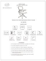
OVERVIEW OF THE
PRIMUS II, MODEL
3.310
The model 3.310 illustrated here is the
standard version.
All deviations are specified separately
in this operating manual. The indicated
items are also applicable for the
PRIMUS II active, model 3.311.
1 Push handle
2 Backrest
3 Armrest with pad
4 Seat cushion
5 Legrest, left (model 3.310 only)
6 Locking device for left legrest
(model 3.310 only)
7 Lower leg strap
8 Foot plate, left (model 3.310)
8 Foot board (model 3.311)
9 Locking device for right armrest
10 Steering wheel - right
11 Pressure brake, left
12 Driving wheel - right
13 Handrim
14 Locking knob / linchpin - right
15 Vario pillow block, right
Remark:
The components shown in the fig-
ures are not always identical with
your wheelchair model. Position
and handling of the parts that are
operated will apply to all wheel-
chair models. Always check that
components are fixed correctly af-
ter assembly as well as after any
adjustment or modification.
PARKING BRAKE
The parking brakes are part of the most
important safety elements of a wheel-
chair.
!
Attention:
Please observe the Maintenance In-
structions as well as instructions in the
section “General Safety Information”
and “Brakes” in the brochure “Safety
information - Mechanical wheel-
chairs”!
Your PRIMUS II is equipped with pres-
sure brakes (Fig. 2) which act directly on
the tyres.
Service brake
Gently and evenly press both brake le-
vers [11] slightly forwards. This way,
you brake the wheelchair in a measured
way.
!
Attention:
If only one brake is applied when the
wheelchair is driving down an in-
cline, the free-running wheel will con-
tinue moving around the locked
wheel. Depending on the gradient of
the road, this can lead to the wheel-
chair overturning to the side.
!
Attention:
Do not park wheelchairs with PU
wheels with applied pressure
brakes. – This can cause accidents
during regular braking due to some
remaining deformation in the sur-
face.

5
GB
PRESSURE BRAKE
Pushing the brake levers to the end stop
locks the brakes and prevents your
wheelchair from being pushed (parking
brakes).
Benefits:
– controlled braking of the driving
speed (service brake)
– Secures the wheelchair against acci-
dental rolling.
Locking the pressure brakes
Push both brake levers (11) forward as
far as they will go (Fig. 4).
!
Attention:
The brake performance decreases
when the:
–tyre profile is worn
–tyre pressure is too low
–tyres are wet
–pressure brake is loose
Any decrease in braking perform-
ance must be repaired immediately
by your specialist workshop.
Releasing the pressure brakes
Pull both brake levers [11] back,
(Fig.2).
PRESSURE BRAKE
Adjusting the pressure brakes
The pressure brakes must be readjusted
after each re-fitting of a drive wheel.
Handling:
Tools
Hexagonal stud wrench WW* 5
– Slacken the clamping screw (A,
Fig.5) of a pressure brake.
– Pre-set the pressure brake. Slide the
brake bolt of the non-activated pres-
sure brake to a point approx. 15mm
to 20mm in front of the drive wheel.
– Tighten the clamping screw (A,
Fig.5).
– Adjust opposite pressure brakes as
described.
– Equally adjust both pressure brakes,
taking into account
• tyres of the driving wheels and
• tyre pressure and
• the weight of the person
adjust evenly. - One-sided braking ac-
tion can cause accidents!
!
Attention:
It should not be possible to push the
wheelchair forward when both
brakes are locked.
Remark:
You will find the values for the cor-
rect air pressure for the wheelchair
in the Technical Specifications.
WW* = Wrench width [mm]
LEGRESTS
Folding up the foot plates
(model 3.310 only)
Benefits:
– Easy transfer into and out of the
wheelchair.
– Leg region free, no stumbling
– “shuffling” possible (moving the
wheelchair forward with the feet).
Handling:
– Operate parking brakes. – This pre-
vents the wheelchair from rolling
away accidentally.
– Remove lower leg strap [7], if
present.
– Remove both feet from the foot
plates
– Fold up foot plates [8] (Fig.9).
!
Attention:
Observe the 'foot plates (legrests)
section' in the 'Safety information -
Mechanical wheelchairs' brochure'!
Turning the legrests to the side
(model 3.310 only)
Benefits:
– Easy transfer into and out of the
wheelchair.
– Leg region free, no stumbling
– “shuffling” possible (moving the
wheelchair forward with the feet).
– Close access to cupboards possible.
– Reduced length of the wheelchair –
for storing the wheelchair
Remark:
Legrest turned to the side are re-
leased automatically and can easi-
ly come off. Note this when han-
dling (e.g. transport).
There is an audible automatic lock-
ing when the legrest is swivelled in
again.

6
LEGRESTS
Handling:
– Operate parking brakes. – This pre-
vents the wheelchair from rolling
away accidentally.
– Remove lower leg strap [7], if
present.
– Remove both feet from the foot
plates
– Fold up foot plates [8] (Fig.9).
– Press the locking lever (A, Fig.10)
outwards and
– Turn legrest [5] to the side (Fig.11).
!
Attention:
Danger of squashing during swivel-
ling out of legrests!
Taking off the legrests
(model 3.310 only)
Benefits:
– Easy transfer into and out of the
wheelchair.
– Foot and side areas are free, no
stumbling
– “shuffling” possible (moving the
wheelchair forward with the feet).
– Reduced length of the wheelchair -
important for storing wheelchair
Handling:
– Operate parking brakes. – This pre-
vents the wheelchair from rolling
away accidentally.
– Remove lower leg strap [7], if
present.
– Remove both feet from the foot
plates
– Fold up foot plates [8] (Fig.9).
– Press the locking lever (A, Fig.10)
outwards. – Legrests have now been
released.
– Turn legrest [5] to the side slightly
and pull up and off (Fig.12).
Attaching the legrests
Handling:
– Insert the hinge pins of legrest (5) into
their sleeves from the top (Fig.12)
and then swivel the legrest inwards.
– Check correct hinge pin insertion and
locking of the legrest!
!
Attention:
Both hinge pins of each legrest must
be inserted into their sleeves.
The locking of the legrest must audi-
bly click when swivelling inwards af-
ter legrest attachment.
Adjusting the length of the
legrests
The legrest length is infinitely adjustable
by 12 cm by way of a non-rotating tele-
scopic tube.
Benefits:
– Individual adjustment of the legrest to
the length of your lower leg
Handling:
Tools:
Hexagonal stud wrench WW* 4
– Operate parking brakes. – This pre-
vents accidental rolling of the wheel-
chair (see section “Parking brakes”).
– Slacken the adjustment screws (A,
Fig 13).
– Push telescopic legrest (5) to re-
quired length.
– Do not forget to
tighten the adjusting screws again.
Remark:
– Observe the 7 cm minimum inser-
tion depth of the telescopic tube!
– Avoid a strong pressure between
thighs and safety belt edge. –
Blood circulation problems!
WW* = Wrench width [mm]
Depth adjustable foot plates/
boards
Benefits:
– You can set the angle between the
tight and lower leg to your most com-
fortable position.
Handling:
Tools Hexagonal stud wrench WW* 5
– Operate parking brakes. – This pre-
vents accidental rolling of the wheel-
chair (see section “Parking brakes”).
– Remove feet from the foot plates/
board (8).
– Screw out the cheese head screws
on the foot plates/board.
– Move the foot plates/board to the
desired position and then screw in
the cheese head screws.

7
GB
ARMRESTS
!
Attention:
Do not lift your wheelchair by the
armrests.
The optional armrests are generally re-
movable and lockable and have arm
pads and a stylish plastic side wall
(Fig.14).
Benefits:
– Easy entry and exit from the wheel-
chair with the removable armrests.
– Lateral support for body
– Relaxation of the shoulder muscles by
resting your lower arm on the arm-
rests.
– Clothes protected against soiling by
the wheels.
– Wind protection.
Removing the armrests
Handling:
– Press in the locking lever (9) in front
of the plastic side wall (Fig.14).
– Remove armrest [3] by pulling up
from the guide tubing.
Installing armrests
Handling:
– Insert the armrests (3), from above,
into the guides (Fig.15 and 16) and
press downwards.
Remark:
The rear mounting pin of the arm-
rest must be inserted in line with the
guide groove (Fig.16).
– The locking mechanism must auto-
matically click into place. – Check
for correct locking!
Armrest height adjustment
Benefits:
– Simple adjustment to suit your per-
sonal requirements
– Reduces muscle tension in the shoul-
der region through individual fitting
– If a seat cushion is used, the armrests
can be adapted to the new seating
level.
Handling:
– Remove screw connection (A,
Fig.14).
– Slide the armrest to your desired
height.
– Assemble screw connection (A,
Fig.14).
DRIVE WHEELS
Remark:
You will find the air pressure values
for the tyres for your wheelchair in
the Technical Specifications or the
information given for both sides of
the wheels.
Linchpin
The driving wheels can be removed and
re-assembled without any tools.
Benefits:
– Simple and quick loading away of
the wheelchair even in small cars.
– Quick and simple replacement of
driving wheels with different tyres.
Handling:
– Push in the stop button [14] in the
centre of the wheel hub (Fig.17) and
– Remove or attach drive wheel [12].
!
Attention:
After installing the drive wheel, the
stop button must protrude a few mil-
limeters from the wheel nut. – The
driving wheel is secured in position.
The stop bolt must be kept clean. A
functional fault may occur in the case
of contamination due to sand or earth
or in the event of freezing of moist
cold air.
Always carry out a tensile test after
each assembly!

8
VARIABLE SEAT HEIGHT
in combination with different sizes and
positions of driving wheel/steering
wheel.
Different seat heights and seat angles
can be achieved by the following chang-
es.
• Changing the size of the driving
wheels.
• Changing the wheel adapter
(Fig.18).
• Changing the size of the steering
wheel.
• Adjusting the angle of the steer-
ing head.
Benefits:
– Individual adaptation of the seat
height to your lower leg length.
– Active driving behaviour by way of
wheel spacing change.
Handling:
Changes should be carried out by your
authorised specialist dealer.
!
Attention:
Moving the wheel adapter forwards
increases the risk of overturning!
The drive wheels should be posi-
tioned at opposite mounting holes for
a perfect driving behaviour.
HANDRIM
All handrims [13] are designed for a
distance to the driving wheel [12] of
15 mm (standard setting) and 25 mm
(Fig.19).
Replacement of handrims or modifica-
tion of handrim distances should always
be carried out by your authorized spe-
cialist workshop.
Remark:
Please observe the section
“Handrims” in your brochure
“Safety Notes- Mechanical
Wheelchairs”!
HAND AND SPOKE
GUARD
The hand and spoke guard prevents inju-
ries to the hands occurring by jamming
in the turning spokes of the wheels, as
well as damage to the spokes.
Handling:
Tools: 2x slot screw drivers
– Dismantle clamping screws of the
disc to be replaced.
– Replace defective disc.
– Position new disc (see note).
– Assemble clamping screws.
Remark:
Gently press the hand and spoke
guard discs through the appropri-
ate grip wheels.
The notches on the circumference
of the discs lie above the handrim
brackets!
All three bores of the discs should
be positioned between two cross-
ing spokes!
STEERING WHEELS
The steering wheels can be exchanged
without difficulty.
Handling:
Tools
1x open-end spanner (WW* 13)
1x hexagonal stud wrench WW* 6
– Dismantle steering wheel screw con-
nection (A, Fig.20).
– Replace steering wheel, if necessary
or re-position to suit your require-
ments.
– Assemble steering wheel screw con-
nection
Remark:
You will find the values for the cor-
rect air pressure for the wheelchair
in the Technical Specifications.
Please note the position of the
washer and the spacer before dis-
assembling the screw connection!
SPECIAL FEATURES OF
MODEL 3.311
for the specialist dealer
The steering head is infinitely adjustable
by 12° with the excenter screw (B,
Fig.21).
The wheel spacing can be changed by
one position. – The screws (C, Fig.22)
must be unscrewed to do this.
The front frame can be replaced
(Fig.23) after the screws (D, Fig.23)
have been unscrewed.
The front frames can be mounted on the
respective opposite located frame side
after the removal of the foot board and
the steering wheels.
The steering wheels are to be mounted
on the outside of the respective frame
tube.
The side change of the front frame
makes a different foot board necessary.
The difference is 8 cm.
!
Attention:
Model 3.311
Excenter screws to adjust the steering
head have to be secured with solu-
ble Loctite glue after every third ad-
justment. – Remove grease and glue
remainders from the flights of the Ex-
center screws or use new Excenter
screws alternatively.
STEERING WHEELS
WW* = Wrench width [mm]

9
GB
FOLDING/UNFOLDING
Your PRIMUS II is foldable (as in Fig.24)
without the use of tools. The new cross-
brace design results in a small folded
size and ensures a high wheelchair sta-
bility after unfolding.
Benefits:
– Easy to fold without any tools.
– High stability of your wheelchair due
to a new crossbrace design.
– Transport possible in a car.
Folding
You achieve the smallest folded size for
stowing the PRIMUS II, for example, in
the car boot or behind the driver or front
passenger seat, as follows:
Handling:
– Remove the seat cushion (4).
– Remove the calf belt (7) upwards.
– Fold up the foot board, respectively,
remove the legrests (5) or remove or
fold up both foot plates (8), (see
'Legrests' section).
– Bend back belt [2] to the rear.
– Pull seatbelt upwards (Fig.24).
Unfolding
Handling:
– Tilt wheelchair to the side towards
you. - The outside driving wheel must
not have any contact with the ground
– Press the inner seat tube downwards
over the dead point of the supporting
crossbrace.
– Attach the legrests (5) or fold down
the foot plates (8) or foot board (see
'Legrests' section).
FOLDING/UNFOLDING
– Check all components for correct
seating!
– Attach the calf belt (7).
– Position the seat cushion (4). - Align
with Velcro strips.
Carrying the wheelchair
Your wheelchair can be carried without
difficulty when folded.
Handling:
– Fold wheelchair (see “Folding”)
– Place one lower arm under the up-
wards folded seat belt.
– Place other hand underneath the rear
seat fold for support.
– Lift wheelchair to horizontal position.
SAFETY BELT
Code 833
The purpose of the safety belt is to strap
in the wheelchair user.
Benefits:
– Additional stabilization of the sitting
position.
– Prevents user from falling forward out
of the wheelchair (depending on de-
gree of disability).
– Continuous adjustment to suit the us-
er’s needs.
!
Attention:
Each end of the belt is fixed to the
back bar with a strap or shoved over
the back bar.
Subsequent fitting of a safety belt
may only be undertaken by your spe-
cialist dealer.
Handling:
The quick-release fastener of the safety
belt facilitates easy and quick fastening
and unfastening.
– Pull belt straps to the front.
– Close belt in front of the body
(Fig.25). – Insert the catch tongue
deep into the catch mechanism until it
audibly clicks (pull to check fastness!).
!
Attention:
Make sure that no objects are
trapped between belt and the body!
– Thus you avoid painful pressure
points
– Unfasten the safety belt by pressing
the red release key on the latch
mechanism (Fig.25).

10
SAFETY BELT
Belt adjustment:
– Hold latch mechanism at a right-an-
gle to the belt.
– Pull the belt in the relevant direction
for lengthening or shortening.
– Secure excess belt material by mov-
ing the plastic slide.
Remark:
The safety belt should be a tight but
not too taut.
Assembly
Slide the loops from below onto the pre-
viously removed back tubes. The arrow
in Fig.26 shows the position of the right
safety belt loop.
The subsequent fitting of the safety belt
may only be carried out by a specialist
dealer!
AIR PUMP
The air pump can be clipped onto one
of the two crossbrace tubes below the
seat.
LOADING INTO THE
TRANSPORT VEHICLE
!
Attention:
For the transport in vehicles, you must
leave the PRIMUS II and occupy a
suitable seat in the vehicle. It is for-
bidden to remain seated in the
PRIMUS II during vehicle transporta-
tion. – Accidents produce forces
which the PRIMUS II is not designed
to handle and therefore seriously en-
danger you as occupant.
If the PRIMUS II is in the transportation
vehicle, proceed as follows:
– Operate parking brakes.
– Stow any parts removed from the
PRIMUS II safely and protectively.
– Remove bags, walking sticks and oth-
er items not belonging to the wheel-
chair and stow these safely.
– Secure the wheelchair by way of
elasticated straps.
!
Attention:
The elastic straps are only to be se-
cured to the appropriate fastening
points of the vehicle and the frame of
the PRIMUS II (Fig.27)!
Remark:
Before transporting the wheel-
chair, ask your car dealer how to
secure it without risk to the existing
fixtures or other safety fittings!
Suitable fixing points can usually be
found in the car and in the vehicle
operating manual.
SERVICE
Maintenance
Like any other technical product, your
PRIMUS II requires maintenance. The
following maintenance instructions de-
scribe in table form the measures neces-
sary in order for you to continue enjoy-
ing the benefits of your wheelchair (e.g.
easy folding, little rolling resistance) to
the full, even after a long period of use.
Care
Seat and backrest cover:
Clean the covers with warm water. In
the case of stubborn soiling, the fabric
can be washed with a standard washing
powder for delicate fabrics. Spots can
be removed with a sponge or a soft
brush.
Remark:
Do not use aggressive cleaning
agents e.g. solvents, or hard brush-
es etc.
Rinse with clear water and let get dry. A
subsequent impregnation with a com-
mercially available aerosol impregna-
tor is recommendable. Always observe
the specific product information.
Plastic parts:
The side walls of the armrests, etc., are
made of high quality plastic. Take care
of these by means of standard plastics
cleaning agents. Always observe the
specific product information.

11
GB
SERVICE
Finish:
The high quality finish ensures an opti-
mum of protection against corrosion. If
the surface finish is damaged by scratch-
es or similar, touch it up with a varnish
pen available from us. Occasional ap-
plication of a light cover of oil to all
moving parts (see also Maintenance In-
structions) will ensure that your wheel-
chair will give you many years of serv-
ice.
A cleaning with a dry cloth is usually suf-
ficient for the maintenance of the
spokes. Use an appropriate brand
name cleaning agent to remove matt
spots or strongly adhering dirt. A thin
Vaseline coating of the spokes will pre-
vent an early matt appearance of the
coating.
Repairs
If any repairs are required, please con-
tact your specialist workshop. Personnel
there are well trained to carry out the
work required.
Customer Service
Should you have any enquiries or need
any assistance, please contact your lo-
cal MEYRA specialized dealer, who has
been trained in our factory in accord-
ance with our guidelines and who can
offer advice, customer service and re-
pairs. We have a dealer network of
approx. 1.500 dealers in germany. In
this way all wishes can be fulfilled.
MAINTENANCE IN-
STRUCTIONS
Checks prior to each use
1. Test brakes for faultless oper-
ation.
– Activate brake lever [11] to the lim-
it. The locked wheels should not be
able to turn under operating condi-
tions. If they can still turn, the brakes
must be repaired by an authorized
specialist workshop.
Remark:
Carry out test yourself or with a
helper.
2. Check pressure brakes for
wear.
– Move brake lever to the side.
Remark:
Do it yourself or with the aid of a
helper. If you notice any increasing
slackness on the brake lever take
the wheelchair to your authorized
specialist workshop immediately
for repairs. – Danger of accidents!
3. Check tyre pressures.
–
Steering wheels:
Standard tyres: 2.5 bar
–
Drive wheels:
Standard tyres: 4.0 bar
Remark:
Do it yourself or with the aid of a
helper. Use a tyre pressure tester
or, if not available, the 'thumb
press' method or similar (see
'Brakes' section in the 'safety infor-
mation').
4. Check tyre profile.
Remark:
Carry out visual check yourself.
If the tyre profile is worn down or if
the tyre is damaged, consult an
authorized specialist workshop for
repairs.

12
TECHNICAL DATA
The product conforms with the
EC Directive 93/42/EEC
(MDD) for medical products.
Tyre fill pressure:
The following pressure values can be
taken as standard values:
Steering wheel:
Standard Code 645 = 2.5 bar
Driving wheel:
Standard Code 486 = 4.0 bar
Always observe the maximum tyre fill
pressure indicated on the tyre cover!
MODEL 3.310
All length and height information in table
1 pertains to the following PRIMUS II
version:
– Seat width 38 cm
– Backrest height 40 cm
– Depth of seat 40 cm
– Armrest code 81
– Drive wheel position central
– Wheel size 24"
– Handrim distance 15 mm
– Lower legrest part code 806
Measuring tolerance ±1.5 mm.
The overall length depends on the posi-
tion and size of the driving wheels.
With the driving wheel position in the
rear, the length is extended by 2 cm.
MODEL 3.311
All length and height information in table
2 pertains to the following PRIMUS II
active version:
– Seat width 38 cm
– Backrest height 40 cm
– Depth of seat 42 cm
– Armrest code 101
– Front position of the driving wheel
– Wheel size 24"
– Handrim distance 15 mm
– Lower legrest part code 54
Measuring tolerance ± 1.5 mm
The overall length depends on the posi-
tion and size of the driving wheels.
With the driving wheel position in the
rear, the length is extended by 4 cm.
!
Attention:
The maximum admissible passenger
weight reduces in accordance with
the number of additional mounted
parts and possible luggage.
The admissible passenger (person)
weight is calculated on the basis of:
maximum passenger weight (Table
1)
– actual weight
= admissible weight for
luggage or mounted parts.
I.e., the passenger and luggage
may not weigh more than the speci-
fied maximum passenger weight of
120 kg.
If the actual weight of the passenger
exceeds the calculated maximum
user (person) weight, reduce the
weight of additional mounted parts
and luggage.
If this is not possible, a more stable
version or another wheelchair model
must be used. Contact your MEYRA
specialist dealer in this respect.
Remark:
The maximum loading is 120 kg.
The continuous foot board code 54
and the stabiliser rod code 138
must be used for safety reasons
when the loading is 100 kg or
greater.
The wheelchair is supplied with a
double crossbrace when the seat
width is 48 cm or greater.

13
GB
013.3ledom,IISUMIRProf1elbaT
]mc[taesfohtdiW234363830434648405
]mc[htdiW
esurofydaer254565850636668607
dedlof53
]mc[htgneL
setalptoofhtiw5.601
setalptoofgnidulcniton97
]mc[thgieH 79
]mc[tserkcabfothgieH 05/54/04/53/03
]mc[taesfohtpeD 05/84/64/44/24/04/83/63/43
]mc[taesfothgieH 05
]mc[stsermraottaeS )noihsuctuohtiw(81
]sehcni[sleehwgnivirD "22/"42
]gk[thgiewdedaolnU 5.71
]gk[*thgiewregnessap.xaM **021
]gk[daollatot.xaM 831
]gk[thgiewtropsnarT )stsergel,stsermra,sleehwevirdtuohtiw(01.nim
113.3ledom,evitcaSUMIRProf2elbaT
]mc[taesfohtdiW234363830434648405
]mc[htdiW
esurofydaer254565850636668607
dedlof13
]mc[htgneL
setalptoofhtiw88
setalptoofgnidulcniton-
]mc[thgieH 29
]mc[tserkcabfothgieH 05/54/04/53/03
]mc[taesfohtpeD 05/84/64/44/24/04/83/63/43
]mc[taesfothgieH 05
]mc[stsermraottaeS )noihsuctuohtiw(81
]sehcni[sleehwgnivirD "22/"42
]gk[thgiewdedaolnU 41
]gk[*thgiewregnessap.xaM **021
]gk[daollatot.xaM 831
]gk[thgiewtropsnarT )sleehwevirdtuohtiw(01.nim

14
NOTES

15
GB
GUARANTEE
Within the scope of our terms of deliv-
ery and payment, we offer the following
guarantees in respect of perfect condi-
tion:
3 years
for frame and crossbrace.
We reserve the right to make technical
improvements.
Should you have any complaints about
the wheelchair or one of its parts,
please do not hesitate to send us the
enclosed guarantee cut-out with your
complaint.
Do not forget to include the requested
information regarding model descrip-
tion, delivery note number with date of
delivery, vehicle identification number
(Fz-I-Nr.) and your retailer.
!
Attention:
Failure to observe instructions in the
operating manual, incorrectly car-
ried out maintenance work and, es-
pecially, technical changes and addi-
tions (add-ons) carried out without the
agreement of MEYRA will lead to
general loss of guarantee and prod-
uct liability.
Remark:
This operating manual is a compo-
nent of the PRIMUS II / PRIMUS II
active folding wheelchair and is to
be handed over whenever a
change of wheelchair user or own-
er occurs.
Vehicle ID no. (Fz-I-Nr.):
Company address:
Meyra-Ring 2
D-32689 Kalletal-
Kalldorf
MEYRA
Wilhelm Meyer GmbH & Co. KG
P.O. Box 1703, D-32591 Vlotho
Telephone +49 (0) 5733 922-0
Fax +49 (0) 5733 922-143
GUARANTEE
Date of delivery:
Delivery note no.:Model designation:
GUARANTEE NOTE
Fill in the details! If necessary, copy and return.
Stamp of the authorized dealer:
WHEELCHAIRS AND REHABILITATION EQUIPMENT
®
The vehicle identification number (Fz-I-
Nr.) is on the type plate (on one side of
the crossbrace).
This guarantee is offered subject to the
use of the wheelchair as per instructions
and the regular implementation of main-
tenance work and inspections.
Damage to the surface, tyres, damage
due to screws and washers which have
worked loose or worn out mounting
holes due to frequent assembly and dis-
mantling are not covered by this guaran-
tee.

16
ST 05/2000 1.000 / BeWa / 205 993 700 (BA052000–T) All technical modifications reserved.
Retailer stamp
MEYRA • Wilhelm Meyer GmbH & Co. KG
Company address: Meyra-Ring 2
D-32689 Kalletal-Kalldorf
Telephone +49 (0) 5733 922-0
Telefax: +49 (0) 5733 922-143
e-mail: [email protected]
Internet: http://www.meyra.de
Postal address:
P.O. Box 1703
• D-32591 Vlotho
WHEELCHAIRS AND REHABILITATION EQUIPMENT

19
F
NL
E
I
D
GB
Bildteil zur Betriebsanleitung
Illustration Section of the Operating Manual
Illustration du mode d`emploi
Illustrazioni relative alle istruzioni d’uso
Fotos para las instrucciones de funcionamiento
Afbeelding voor Gebruiksaanwijzing
FALT-ROLLSTUHL
ROLLSTÜHLE UND REHABILITATIONSMITTEL
Modell 3.310
Modell 3.311

20
2
4
9
10
12
1
516
5
1
1
14
13
A
A
A
9
A
17
14

21
1
8
19
22
24
27
20
23
26
25
A
B
C
21
D
D

22
ST 05/2000 1.000 / BeWa / 205 993 700 (BA052000–A) Technische Änderungen vorbehalten.
Stempel vom Fachhändler:
MEYRA
•
Wilhelm Meyer GmbH & Co. KG
Firmensitz: Meyra-Ring 2
D-32689 Kalletal-Kalldorf
Telefon (05733) 922-0
Telefax: (05733) 922143
Email: [email protected]
Internet: http://www.meyra.de
Postanschrift:
Postfach 1703
•
D-32591 Vlotho
ROLLSTÜHLE UND REHABILITATIONSMITTEL
/