Midmark Synthesis® Cabinetry Installation guide
- Type
- Installation guide


2
TP200 Rev. A
© 2015 Midmark Corp. | 60 Vista Drive Versailles, OH 45380 USA | 1-800-643-6275 | 1-937-526-3662 |
Receiving Truck / Shipment
The following will assist the installer or dealer in getting the truck to the dock
and unloaded. It will be necessary for the installer to be on site prior to the
trucks arrival, so that the best point of delivery for the product can be deter-
mined.
If the installer has been given an exact time of arrival and the truck does not
arrive on time, the foreman must notify Midmark within eight hours. Midmark
will not be liable for any charges if notied later than eight hours of the
scheduled arrival time.
All wrapped products must be unwrapped from the blankets in the trailer.
The blankets and rubber bands need to be returned to the trailer prior to the
trailer leaving the site. All boxed products will remain in the boxes until instal-
lation.
The cabinets and top surfaces may be wrapped in blankets or boxed. The
product will have labels marked for model number, description, date, room
number, and will have a line drawing of the cabinet.
IF ANY PRODUCT APPEARS TO HAVE DAMAGE DUE TO FREIGHT,
PLEASE NOTE IT ON THE “BILL OF LADING”.
Safety
A primary concern of Midmark is that this equipment be operated and main-
tained with the safety of the users in mind. To assure safer and more reli-
able operation, do the following: (1) Read this manual before operating your
equipment; (2) Assure that appropriate personnel understand the contents of
this manual--responsibility of the purchaser; (3) Understand the instructions
contained in this manual before attempting to install this equipment.
Explanation of Symbols
Introduction
This installation guide has been prepared to assist in the installation of
Midmark modular casework. Careful and proper installation of these units
are in the best interest of the Customer, Distributor, and Midmark. Following
these instructions will assure proper installation and will simplify the task.
Special conditions may be encountered that are not described in this manu-
al. Should this occur during an installation, contact your local distributor for
assistance or Midmark at 1-800-643-6275.
Note
Amplifies a procedure, practice, or condition.
Equipment Alert
Indicates a potentially hazardous situation which could result in
equipment damage if not avoided.
Caution
Indicates a potentially hazardous situation which may result in minor
or moderate injury if not avoided. It may also be used to alert against
unsafe practices.
Equipment Alert
While unloading truck, make sure to avoid damage to the cabinets.
Do not use sharp objects to cut packaging from the cabinets.
midmark.com

3
TP200 Rev. A
© 2015 Midmark Corp. | 60 Vista Drive Versailles, OH 45380 USA | 1-800-643-6275 | 1-937-526-3662 |
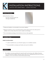
Towel/Cup/Glove Dispenser and Dressing Nook Installation
Step 1:
Remove screws (2) from door stay and door from nook also remove hanging brackets. Remove
door, hanging bracket and plastic insert from dispenser (if applicable) for easier installation.
Towel
Guides
Plastic
Insert
Flap
Stay
Hanging
Bracket
Hanging
Brackets
Hinge
midmark.com

4
TP200 Rev. A
© 2015 Midmark Corp. | 60 Vista Drive Versailles, OH 45380 USA | 1-800-643-6275 | 1-937-526-3662 |
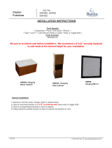
Step 3:
Choose location of unit and measure up from floor to
mark desired top height using level to extend line.
Desired
Height
Step 4:
Measure 2-1/16” (5.2 cm) down from desired
height of unit and mark for bottom of hanging
bracket using level to extend line.
2-1/16”
(5.2 cm)
Desired
Height
Bottom of
Hanging
Bracket
Step 2:
See Synthesis
TM
Casework Collection dimensions above
to determine recommended height of Dispenser Unit.
Dispenser
Unit
Towel/Cup/Glove Dispenser Installation
Dispenser
Unit
midmark.com

5
TP200 Rev. A
© 2015 Midmark Corp. | 60 Vista Drive Versailles, OH 45380 USA | 1-800-643-6275 | 1-937-526-3662 |
Step 5:
Mount hanging bracket(s) to wall using hardware
(not supplied).
Note: Suggested Fasteners
- Stud walls (standard): #10 x 2 wood screws
(coarse threaded).
- Steel studded walls: sheet metal #10 fine screws.
- Hollow type or masonary walls: #10 machine screw
expansion anchors of adequate length. A 3/16” short
molly or other type of fastener may be used if
pre-drilled.
- Rough solid concrete or brick wall: #10 round head
wood screw or a specialized masonary fastener.
Caution
Installer must secure bracket to at least one
stud and use wall anchors on any screws that
cannot be secured to studs.
Attention:
Local, city, or national building codes should be followed
before using midmark suggested fasteners for installation.
Wall
Hanging
Bracket
Top
Towel/Cup/Glove Dispenser Installation
Step 6: Dispenser
Place dispenser onto hanging bracket. Dispenser
with Cup/Towel secure to wall using hardware (not
supplied) (x2 screws) then reinstall plastic insert.
midmark.com

6
TP200 Rev. A
© 2015 Midmark Corp. | 60 Vista Drive Versailles, OH 45380 USA | 1-800-643-6275 | 1-937-526-3662 |
Step 7: Dispenser
Reinstall door onto unit. (x2 hinges)
Step 8: Install Cups and Glove Boxes.
Place standard 5 oz. cups into dispenser hole.
Remove lid from glove box and slide box into slot secure
with bungee strap, may need to twist for thin boxes.
Towel/Cup/Glove Dispenser Installation
Step 9: Install “C” Style Towels.
Place “C” style towels face down. Place towel
guide in outside slots for these towels.
Step 9: Install “Z” Style Towels.
Place “Z” style towels face down. Place towel
guide in inside slots for these towels.
midmark.com


8
TP200 Rev. A
© 2015 Midmark Corp. | 60 Vista Drive Versailles, OH 45380 USA | 1-800-643-6275 | 1-937-526-3662 |
Dressing Nook and Instrument Panel Installation
Step 4:
Measure 2-1/16” (5.2 cm) down from desired
height of unit and mark for bottom of hanging
bracket using level to extend line.
Step 3:
Choose location of unit and measure up from floor
to mark desired top height using level to extend line.
Note: Refer to previous step for recommended heights.
2-1/16”
(5.2 cm)
Desired
Height
Bottom of
Hanging
Bracket
Desired
Height
Step 2:
See SynthesisTM Casework Collection dimensions above
to determine recommended height of Dressing Nook.
Step 5:
Measure down and mark 60-13/16” (154.5 cm) from the
bottom of the top hanging bracket. Use level to extend
line for lower hanging bracket. Note: Position lower
bracket in same position (left to right) as upper bracket.
60-13/16”
(154.5 cm)
Bottom of
Hanging
Bracket
midmark.com

9
TP200 Rev. A
© 2015 Midmark Corp. | 60 Vista Drive Versailles, OH 45380 USA | 1-800-643-6275 | 1-937-526-3662 |
Step 7: Dressing Nook
Reinstall door onto unit. (x4 hinges) and attach
flap stay with screws (2) to cabinet.
Step 6: Dressing Nook
Place Dressing Nook onto hanging brackets.
Dressing Nook and Instrument Panel Installation
Step 5:
Mount hanging bracket(s) to wall using wall
anchors and drywall screws provided.
Note: Suggested Fasteners
- Stud walls (standard): #10 x 2 wood screws
(coarse threaded).
- Steel studded walls: sheet metal #10 fine screws.
- Hollow type or masonary walls: #10 machine screw
expansion anchors of adequate length. A 3/16” short
molly or other type of fastener may be used if
pre-drilled.
- Rough solid concrete or brick wall: #10 round head
wood screw or a specialized masonary fastener.
Caution
Installer must secure bracket to at least one
stud and use wall anchors on any screws that
cannot be secured to studs.
Attention:
Local, city, or national building codes should be followed
before using midmark suggested fasteners for installation.
Wall
Hanging
Bracket
Top
69-7/8”
(177.5 cm)
4”
(10.2 cm)
Step 8: Instrument Panel
Measure from the floor up 69-7/8” (177.5 cm)
for bottom of hanging bracket.
Step 9:
Recommended distance from side of dressing
nook to instrument panel is 4” (10.2 cm)
Bottom of
Hanging
Bracket
midmark.com

10
TP200 Rev. A
© 2015 Midmark Corp. | 60 Vista Drive Versailles, OH 45380 USA | 1-800-643-6275 | 1-937-526-3662 |
Dressing Nook and Instrument Panel Installation
Note: Suggested Fasteners
- Stud walls (standard): #10 x 2 wood screws (coarse thread).
- Steel studded walls: #10 sheet metal screws (fine thread)
- Hollow type or masonary walls: #10 machine screws with
expansion anchors of adequate length. A 3/16” short molly
or other type of fastener may be used if pre-drilled.
- Rough solid concrete or brick wall: #10 round head
wood screw or a specialized masonary fastener.
- Wall Transformer: #8 x 3/4” pan-head, wood screws
- Blood Pressure System Holder: #8 x 3/4” pan-head, wood
screws with #8 plain washers
Caution
Installer must secure bracket to at least one
stud and use wall anchors on any screws that
cannot be secured to studs.
Attention:
Local, city, or national building codes should be followed
before using midmark suggested fasteners for installation.
Wall
Hanging
Bracket
Top
Step 10:
Mount hanging bracket(s) to wall using hard-
ware (not supplied).
Step 11:
Install Instrument panel onto hanging bracket.
Step 12: Mount Wall Transformer, Tip Dispenser and Blood Pressure System Holder onto the Panel
Position keyhole screws with template to mount the wall transformer at a convenient height. Hang the wall
transformer from the keyhole screws in the panel and secure with two more screws in the front Use double-sided
tape to mount the tip dispenser. Mount the blood pressure system holder using two screws with washers.
Step 13:
Refer to the instructions that come with Midmark
Heine kits to finish the installation.
Blood
Pressure
System
Holder
Wall Transformer
Double-sided
Tape
Position the kits to t the panel
(2 options shown)
Tip Dispenser
midmark.com

11
TP200 Rev. A
© 2015 Midmark Corp. | 60 Vista Drive Versailles, OH 45380 USA | 1-800-643-6275 | 1-937-526-3662 |
Dressing Nook Door Reversal
Step 2: Remove Flap Stay
Remove screws (2) from inside cabinet from flap
stay. Remove screws (3) from bracket on door.
Step 3: Install Flap Stay and Remove Door.
Install flap stay on opposite side of cabinet as
shown. Remove dressing nook door. (4 hinges)
Step 5: Install Hinges and Shoe Holder
Mount shoe holder with screws (4) on opposite side
of cabinet. Attach hinge plates (4) with screws(8).
Step 6: Install Door and Flap Stay.
Reinstall door onto cabinet (x4 hinges). To install flap
stay, open door to full extension. Flap stay must be level
before securing flap stay bracket to door with screws (3).
Step 4: Remove Hinges and Shoe Holder
Remove screws (4) from shoe holder. Remove
screws (8) and hinge plates (4) from inside cabinet.
Step 1: Rotate Mirror
Remove screws (2) and washers (2) from mirror door-
handle. Rotate mirror 180° and secure with washers
and screws.
Screws
Washer
Mirror
Door
Mirror
Screws
Flap Stay
Screws
Flap Stay
Screws
Hinge
Plate
Screws
Hinge
Plate
Screws
Screws
Screws
Door
Hinge
Keep Door
Bracket
Screws
Flap
Stay
midmark.com

12
TP200 Rev. A
© 2015 Midmark Corp. | 60 Vista Drive Versailles, OH 45380 USA | 1-800-643-6275 | 1-937-526-3662 |
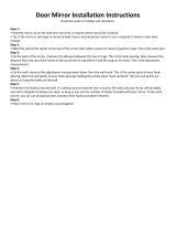
Door Adjustment
Door Adjustment Up and Down
Turn cam screw located in center of mounting plate to
adjust door position up or down (+ or - 2 mm).
Door Adjustment Away or Closer
Turn Spiral Tech cam screw located furthest from door
to position the door farther from or closer to cabinet
(+3 mm or -2 mm).
Door Adjustment Side to Side
Turn screw located closest to door to increase or decrease
the door overlay side to side (+ or - 2 mm).
Left
Right
Down
Up
In
Out
Turning off/on Soft-Close Door Hinge
Push switch toward hinge plate and close door once to
turn off soft-closing hinge. Reactivate Soft-close hinge
pushing switch towards door handle.
On
1
2
003-2835-00 (9/4/18)
midmark.com
-
 1
1
-
 2
2
-
 3
3
-
 4
4
-
 5
5
-
 6
6
-
 7
7
-
 8
8
-
 9
9
-
 10
10
-
 11
11
-
 12
12


Midmark Synthesis® Cabinetry Installation guide
- Type
- Installation guide
Ask a question and I''ll find the answer in the document
Finding information in a document is now easier with AI
Related papers
-
Midmark Synthesis® Cabinetry Installation guide
-
-
-
-
-
-
Midmark LED Dental Light Installation guide
-
Midmark Integra™ Operatory Cabinetry - Side Cabinetry Installation guide
-
Midmark 355 Diagnosis and Treatment Light (Wall, 355-042) Installation guide
-
Midmark Dental Light (Halogen) Installation guide
Other documents
-
Alpine Industries 451-SSB Installation guide
-
-
 Ketcham Cabinets Ketcham-SSF-2436 Installation guide
-
 Barclay Products SWHM-CH Installation guide
-
Barnes & Noble Nook HD User manual
-
 Amanti Art DSW3940198 Installation guide
-
 NOOK GlowLight User manual
-
-
GATCO 1562 Installation guide
-
Unbranded SJMT1790TBK Installation guide


