NTI RACKMUX-V17-4UNV User manual
- Category
- Rack consoles
- Type
- User manual
This manual is also suitable for

MAN089 Rev Date 10/23/2007
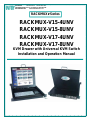
RACKMUX-V15-4UNV
RACKMUX-V15-8UNV
RACKMUX-V17-4UNV
RACKMUX-V17-8UNV
KVM Drawer with Universal KVM Switch
Installation and Operation Manual
RACKMUX
®
Series
NETWORK
TECHNOLOGIES
INCORPORATED
Tel:330-562-7070
Fax:330-562-1999
1275 Danner Dr
Aurora, OH 44202
www.networktechinc.com
NTI
R

i
TRADEMARK
RACKMUX is a registered trademark of Network Technologies Inc in the U.S. and other countries.
COPYRIGHT
Copyright © 2007 by Network Technologies Inc. All rights reserved. No part of this publication may be reproduced, stored in a
retrieval system, or transmitted, in any form or by any means, electronic, mechanical, photocopying, recording, or otherwise,
without the prior written consent of Network Technologies Inc, 1275 Danner Drive, Aurora, Ohio 44202.
CHANGES
The material in this guide is for information only and is subject to change without notice. Network Technologies Inc reserves the
right to make changes in the product design without reservation and without notification to its users.

ii
TABLE OF CONTENTS
INTRODUCTION.............................................................................................................................................................1
Models Available.......................................................................................................................................................1
Types of CPUs Supported........................................................................................................................................1
Features....................................................................................................................................................................1
MATERIALS....................................................................................................................................................................2
FEATURES AND FUNCTIONS.......................................................................................................................................3
INSTALLATION...............................................................................................................................................................4
Rack Mounting Instructions .........................................................................................................................................4
Connect The Cables....................................................................................................................................................4
Power-Up Sequence....................................................................................................................................................6
USING THE RACKMUX..................................................................................................................................................7
Keyboard Control.........................................................................................................................................................7
OSD Control ................................................................................................................................................................7
Security Option .........................................................................................................................................................7
Enabling the Security Feature ..................................................................................................................................7
User Login Mode.......................................................................................................................................................8
Additional Modes Available With Security...................................................................................................................8
Administration Mode.................................................................................................................................................8
Switch Configuration.................................................................................................................................................9
Exit Switch Configuration Mode.............................................................................................................................9
Administrator Password..........................................................................................................................................10
User Name List.......................................................................................................................................................10
System Access List.................................................................................................................................................11
User Access Functions..............................................................................................................................................11
Command Mode.....................................................................................................................................................11
Broadcast Mode......................................................................................................................................................13
Scan Mode..............................................................................................................................................................13
Normal Mode ..........................................................................................................................................................13
Edit Mode................................................................................................................................................................13
Search Mode...........................................................................................................................................................14
Maintenance Mode.................................................................................................................................................15
Help Mode...............................................................................................................................................................16
RS232 CONTROL.........................................................................................................................................................16
RS232 Connections and Configuration.....................................................................................................................16
Remote Connection................................................................................................................................................16
Configuration .............................................................................................................................................................17
Baud Rate...............................................................................................................................................................17
Loop Back...............................................................................................................................................................17
Unit Address ...........................................................................................................................................................18
Exit Switch Configuration Mode..............................................................................................................................18
Command Protocol....................................................................................................................................................18
Display Functions..........................................................................................................................................................21
Standard Controls......................................................................................................................................................21
OSD Control Menu ....................................................................................................................................................21
OSD Main Menu .....................................................................................................................................................21
Brightness/Contrast Menu......................................................................................................................................22
Color Menu .............................................................................................................................................................22
Position Menu.........................................................................................................................................................22
Setup Menu.............................................................................................................................................................23
Keyboard Functions ......................................................................................................................................................24
RACKMUX-V15-x......................................................................................................................................................24
Function Key Operation..........................................................................................................................................24
Number Pad...............................................................................................................................................................25
Other Functions of the "Fn" Key................................................................................................................................26
Numeric Keypad Option.............................................................................................................................................27
KEYBOARD FEATURES..............................................................................................................................................28
Keyboard-To-Computer Translation..........................................................................................................................28

iii
Translation Capabilities ..........................................................................................................................................28
Translation Tables ..................................................................................................................................................28
TROUBLESHOOTING..................................................................................................................................................29
DEFAULT PASSWORD RESET...................................................................................................................................29
Rackmux-KVM Drawer Standard Specifications...........................................................................................................30
General Specs...........................................................................................................................................................30
LCD – 15” ..................................................................................................................................................................30
LCD – 17” ..................................................................................................................................................................30
Display Controller: VGA (-15 & -17) ..........................................................................................................................30
OSD Control Board....................................................................................................................................................30
Keyboard....................................................................................................................................................................31
Touchpad...................................................................................................................................................................31
INDEX............................................................................................................................................................................31
WARRANTY INFORMATION........................................................................................................................................31
TABLE OF FIGURES
Figure 1- Mount RACKMUX to rack...................................................................................................................................................4
Figure 2- Connect a PS/2 CPU..........................................................................................................................................................5
Figure 3- Connect a legacy SUN CPU...............................................................................................................................................5
Figure 4- Connect the power cord and AC adapter ...........................................................................................................................6
Figure 5- Administrator Login screen.................................................................................................................................................7
Figure 6- User Login screen ..............................................................................................................................................................8
Figure 7- Administration Mode menu.................................................................................................................................................8
Figure 8- Switch Configuration Mode screen.....................................................................................................................................9
Figure 9- Administrator password change .......................................................................................................................................10
Figure 10- User Name List screen...................................................................................................................................................10
Figure 11- Command Mode menus .................................................................................................................................................12
Figure 12- Edit Mode screen............................................................................................................................................................13
Figure 13- Search Mode screen ......................................................................................................................................................14
Figure 14- Maintenance Mode screen .............................................................................................................................................15
Figure 15- Switch Configuration Mode screen.................................................................................................................................17
Figure 16- Daisy chain configuration with Matrix-Y-1 cable.............................................................................................................17
Figure 17- Matrix-Y-1 wiring schematic............................................................................................................................................18
Figure 18- OSD Controls .................................................................................................................................................................21
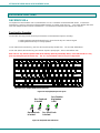
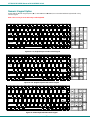
Figure 19- US(English) Keyboard Layout ........................................................................................................................................24
Figure 20- Keyboard LED Indications..............................................................................................................................................24
Figure 21- Keys of the Number Pad ................................................................................................................................................25
Figure 22- Additional multi-function keys.........................................................................................................................................26
Figure 23- U.S. (English) keyboard with numeric keypad................................................................................................................27
Figure 24- U.K. (English keyboard with numeric keypad.................................................................................................................27
Figure 25- German keyboard with numeric keypad.........................................................................................................................27
Figure 26- Locating the password reset button................................................................................................................................29

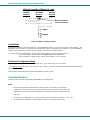
NTI RACKMUX KVM Drawer with NODEMUX Switch
1
INTRODUCTION
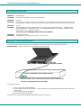
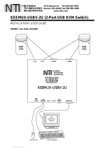
The RACKMUX-V15-8UNV (RACKMUX) is a KVM Drawer with Universal KVM Switch that combines a rackmount 15" TFT/ LCD
monitor, keyboard, touchpad mouse, an 8-port Universal KVM switch (NODEMUX) in a space-saving 1RU industrial strength
drawer with wrist pads. The RACKMUX is equipped with a built-in switch function, which allows control of up to eight (8)
Windows or SUN-enabled CPUs with a single keyboard, touchpad and monitor. When access to a server rack is needed, the
drawer can be pulled out and the display lifted up like a notebook computer, revealing the keyboard and touchpad. When the
drawer is not in use, the display can be folded forward and down so the 1RU drawer can be pushed into the cabinet easily and
smoothly, helping to organize and streamline busy server rooms.
The onboard Universal KVM switch allows access to any Windows or SUN legacy CPUs from one monitor, keyboard and mouse
(up to 8 CPUs). These CPUs can be file servers, network managers, etc. Internal microprocessor circuitry allows all CPUs to be
booted simultaneously without keyboard error. Port selection is accomplished through On Screen Display (OSD) menus provided
for switch control and security administration.
Models Available
¾ RACKMUX-V15-4UNV - KVM Drawer with 15" TFT/LCD monitor and 4-port NODEMUX
¾ RACKMUX-V17-4UNV - KVM Drawer with 17" TFT/LCD monitor and 4-port NODEMUX
¾ RACKMUX-V15-8UNV - KVM Drawer with 15" TFT/LCD monitor and 8-port NODEMUX
¾ RACKMUX-V17-8UNV - KVM Drawer with 17" TFT/LCD monitor and 8-port NODEMUX
Types of CPUs Supported
• PS/2 (i.e. WINxx)
• Legacy SUN
• USB (when used with NTI USB-PS2 or USB-SUN Adapter)
Features
• Entire unit is only 1RU (1.75") high
• High-quality metal construction (ideal for most industrial and commercial settings)
• 15" or 17" Rack Mount LCD Monitor features a wide viewing angle
• 1024X768 resolution for 15" XGA monitor
• 1280x1024 resolution for 17" SXGA monitor
• A forward-folding 15” or 17” TFT LCD with built-in OSD menu for screen adjustments
• LCD Power-up when raised; manual override
• LCD Display controls (using on-screen menu)
• Includes rack mount kit suitable for SUN and most EIA 19" racks
• Fits varying rack depths from 22” to 39” deep via adjustable mounting brackets
• VGA/SVGA/XGA/SXGA Compatible
• Powered by 110-240VAC, 50 or 60Hz via IEC connector and country-specific line cord
• Auto shut-OFF switch: Turns OFF the power to the monitor when the LCD is in a folded-closed position
• Standard 3-button touchpad
• Added security with a drawer lock to prevent unwanted access
• Locking rails to prevent movement of the drawer when fully extended
• Keyboards available in multiple languages: English(US), English(UK), German, Italian, French, and Spanish
Option:
• Numeric keypad option- for a separate 17-key numeric keypad, add “-N” to the part number (i.e. RACKMUX-V17-N-8UNV)

NTI RACKMUX KVM Drawer with NODEMUX Switch
2
MATERIALS
Materials supplied with this kit:
• NTI RACKMUX-V15/17-4/8UNV KVM Drawer with Universal KVM Switch
• Line cord, country specific
• set of keys for keylock
• 2 Rear Mounting Brackets w/nuts
• 8 #10-32x3/4” screws and cage nuts for mounting to a rack
• CD with a pdf of this manual
Materials Not supplied but REQUIRED:
• A set of 2 cables for each CPU being connected to the switch:
• PS/2
CPU to Switch
- VEXT-xx-MM for video
interface
- VKTINT-xx-MM for keyboard and mouse
interface
OR
• Legacy SUN
CPU to
Switch
- VEXT-xx-MM for video
interface
- 13W3M-15HDF (adapter for 13W3 to 15HD)
- SKTINT-xx-MM for keyboard/mouse interface
where:
xx is the length of the cable in feet
MM indicates male-to-male connector
Cables can be purchased from Network Technologies Inc by calling (800) 742-8324 (800-RGB-TECH) in the US and Canada or
(330) 562-7070 (worldwide).

NTI RACKMUX KVM Drawer with NODEMUX Switch
3
FEATURES AND FUNCTIONS
1. Power Button- press to turn the LCD monitor ON and OFF
2. Power LED- Indicates operation status
Green = Power-ON, Video Input Signal OK
Red = Suspend / Stand-by, or no Video Input Signal
3. Menu Button- press to turn ON the OSD menu
4. Up Arrow Button- press to move the cursor in the OSD menu up
5. Down Arrow Button- press to move the cursor in the OSD menu down
6. Select Button- press to select a menu item (when OSD menu is ON) or press to auto adjust the video quality (when OSD
menu is OFF)
7. NumLock LED- illuminates when the number lock is ON
8. CapsLock LED- illuminates when CapsLock is ON.
9. Scroll Lock LED- illuminates when the Scroll Lock keyboard feature is ON.
10. Fn LED- illuminates when Function Features (page 24) are enabled.
11. LCD Display- for viewing the video signal from the connected CPU
12. Auto Shut-OFF- switch automatically shuts OFF the LCD display when the monitor is folded down
13. 3-button touch pad- for controlling mouse movements on the monitor and controlling the computer
14. Keylock- to prevent unauthorized use of the RACKMUX
15. keyboard- for manual data entry and computer control
16. wrist rest- for user comfort
17. IEC Connector w/Built-in 2A 240VAC Replaceable Fuse- for attachment of the IEC power cord to power the RACKMUX
drawer
18. Switch- for powering ON and OFF the RACKMUX drawer
19. RS232- 9D female connector- for attaching RS232 interface cable from a remote terminal to control the functions of the
NODEMUX switch
20. CPU x- 8 pin miniDIN female connector-for connection of device cable from CPU(s)
21. VIDEO x- 15HD female connectors- for connecting video cables from CPUs
Front View
RACKMUX-V15-8UNV
11
15
14
12
1
A
9
8
7
Fn
10
16
13
1
2
3
4
5
6
19
Rear View
RACKMUX-V15-8UNV
20
2118
17

NTI RACKMUX KVM Drawer with NODEMUX Switch
4
INSTALLATION
Rack Mounting Instructions
The RACKMUX was designed to be mounted to a rack and includes mounting flanges to make attachment easy.
1. Determine the mounting height in the rack for the drawer. It should be a height comfortable to use the keyboard and see the
LCD display. Mark holes in each of the 4 corner cabinet rails at points all level with each other.
2. Secure the rear brackets to the rear rack cabinet rails. Apply the top screws (not supplied) for each bracket to the holes
marked in step 1.
3. Lift the keyboard into position and line the studs on the left and right sides up with the slotted openings in the rear bracket.
Apply the nuts (supplied) to the studs but do not tighten the nuts yet.
FYI: There are 3 mounting studs provided on each side of the RACKMUX. Depending on the depth of the rack and
distance apart of the cabinet rails, the position of the rear bracket may make all 3 studs available for use. In this case,
apply the 2 nuts to the studs furthest apart from each other on each side.
4. Slide the drawer in until the top holes in the front bracket flanges line up with the holes marked in step 1. Secure the front
brackets on the drawer to the front cabinet rails with two screws per bracket. Be sure to tighten the screws securely. Then
tighten the nuts applied in step 3.
5. Apply one more screw to each of the rear brackets to finish.
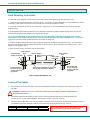
Figure 1- Mount RACKMUX to rack
Connect The Cables
1. Turn OFF power to all CPUs that will be connected to the NODEMUX before connecting or disconnecting any cables to or
from them.
WARNING! DAMAGE MAY OCCUR TO THE CPU IF POWER IS NOT DISCONNECTED BEFORE CONNECTING OR
DISCONNECTING CABLES.
2. Connect the appropriate NTI keyboard cable (see the chart below) from the input devices port (keyboard/mouse)
of a CPU to a CPUx port of the NODEMUX. Note the port’s number. (See Figs. 2 and 3.)
3. Connect a VEXT-xx-MM video cable and video adapter, if needed (see the chart below), from the video port of the same CPU
to the VIDEOx port of the NODEMUX with the same port number as the keyboard (see Figs. 2 and 3).
CPU Keyboard Cable Video Cable Video Adapter
PS/2 VKTINT-xx-MM VEXT-xx-MM None needed
SUN SKTINT-xx-MM VEXT-xx-MM 15DM-15HDF
!
NOTE: Make sure the CPU is connected to a CPU x
port and a VIDEO x port with the same number.
Apply nuts (supplied) to studs and
secure rear brackets to drawer.
Front bracket
flange on drawer
Rear bracket
flange
Drawer
Front Cabinet
Rail
Rear Cabinet
Rail
Rear bracket overlapping
drawer
(Rear edge
of drawer)
Stud on drawer
Secure bracket
to rail using two
screws and nut
s
(supplied)
Secure bracket
to rail using two
screws and nuts
(supplied)

NTI RACKMUX KVM Drawer with NODEMUX Switch
5
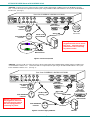
• PS/2 CPU- Connect a PS/2 CPU video port using a VEXT-xx-MM cable between a VIDEOx port on the NODEMUX and the
CPU. Connect the PS/2 CPU keyboard and mouse ports using a VKTINT-xx-MM cable between a CPUx port on the NODEMUX
and the CPU. (See Fig.2.)
Figure 2- Connect a PS/2 CPU
• SUN CPU- Connect a SUN CPU video port using a VEXT-xx-MM cable with a 13W3M-15HDF adapter between a VIDEOx port
on the NODEMUX and the CPU. Connect the SUN CPU keyboard/mouse port using an SKTINT-xx-MM between a CPUx port
on the NODEMUX and the CPU. (See Fig. 3.)
Figure 3- Connect a legacy SUN CPU
Warning: Hardware is not hot -
pluggable at switch end of cable to
PS/2 CPUs. PS/2 CPUs must be
powered OFF before connecting
any cables to switch
Warning: Hardware is not
hot-pluggable to SUN CPUs.
SUN CPUs must be powered
OFF and unplugged before
connecting any cables.
13W3M-15HDF
Sun 13W3 Male
Video Connector
8 Pin miniDIN
Female
Connector
15HD Female
Video Connector
8 4 7 3 6 2 5 1
VIDEOVIDEO
NETWORK TECHNOLOGIES INC Tel:330-562-70701275 Danner Dr, Aurora, OH 44202 www.nti1.com
Rear View of NODEMUX in RACKMUX-V15-8UNV
CPU 4
CPU 3
CPU 2 CPU 1
CPU 8
CPU 7
CPU 6 CPU 5
SKTINT-xx-MM
VEXT-xx-MM
15HD Male
Video Connector
8 Pin miniDIN Male
Connector
SUN CPU
8 Pin miniDIN Male
Connector
8 Pin miniDIN
Female
Connector
15HD Female
Video Connector
8 4 7 3 6 2 5 1
VIDEOVIDEO
NETWORK TECHNOLOGIES INC Tel:330-562-70701275 Danner Dr, Aurora, OH 44202 www.nti1.com
Rear View of NODEMUX in RACKMUX-V15-8UNV
CPU 4
CPU 3
CPU 2 CPU 1
CPU 8
CPU 7
CPU 6 CPU 5
PS/2 CPU
VKTINT-xx-MM
VEXT-xx-MM
15HD Male
Video Connector
8 Pin miniDIN Male
Connector
(GREEN-MOUSE)
(PURPLE-KEYBOARD)
6 Pin miniDIN
Male Connector

NTI RACKMUX KVM Drawer with NODEMUX Switch
6
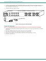
4. Connect the remaining input device and monitor interface cables from each CPU, making sure that cables from the each CPU
are connected to the NODEMUX switch at connectors with the same port numbers ("CPU 1" and "VIDEO 1 connectors,
"CPU 2" and "VIDEO 2" connectors...etc. )
5. Connect the power cord to the IEC connector.
Figure 4- Connect the power cord and AC adapter
Power-Up Sequence
Note: It is very important that this power-up sequence be followed for all connected components to work properly.
1. Using the key, unlock the drawer and slide the keyboard and LCD Display out far enough to raise the display to a comfortable
viewing angle.
2. Power ON the NODEMUX with the power switch located at the rear of the RACKMUX.
3. Power ON the KVM Drawer with the power switch located at the rear of the keyboard.
4. Adjust the screen's brightness and contrast with the controls also located on the monitor– as needed.
5. Power ON any attached CPUs.
IEC Power Cord
8 4 7 3 6 2 5 1
VIDEOVIDEO
NETWORK TECHNOLOGIES INC Tel:330-562-70701275 Danner Dr, Aurora, OH 44202 www.nti1.com
Rear View of NODEMUX in RACKMUX-V15-8UNV
CPU 4
CPU 3
CPU 2 CPU 1
CPU 8
CPU 7
CPU 6 CPU 5
IEC Connectxor

NTI RACKMUX KVM Drawer with NODEMUX Switch
7
USING THE RACKMUX
Once the RACKMUX is properly connected, the NODEMUX will enable a connection to be made between the attached CPUs and
the monitor, keyboard, and mouse.
The NODEMUX can be controlled by three methods:
• keyboard control through Command Mode
• mouse clicks from within some menus of Command Mode
• RS232 control from a remote terminal
Keyboard Control
Keyboard control of the NODEMUX is achieved using Command Mode - operated using the keyboard and mouse in
conjunction with OSD menus superimposed onto the monitor.
By pressing <Ctrl> + < ` > (accent key), the user can enter Command Mode. Once in Command Mode, typing a series of
commands will cause the NODEMUX to connect the user to any one CPU connected to the switch. Pressing the <Esc> key will
exit Command Mode. The following instruction describes how to use the menus to operate the NODEMUX Universal KVM switch.
OSD Control
OSD superimposes a menu system on the user’s video screen with a list of all connected CPUs. OSD allows CPUs to be named
(with up to 12-character names). OSD then allows selection of CPUs by that name. Connected CPUs can be listed by name or
by port number. OSD Search Mode enables the user to type in the first few characters of the CPU's name and the OSD will locate
it. Help screens assist with all OSD functions.
Security Option
The security option of the OSD Control enables an administrator to control access to CPU ports for each user. Up to 63 users
can be created. These users have controlled access to any selected CPU. Only the administrator can activate or deactivate the
security features. Security can be activated from the Maintenance Mode menu (page 15) with a successful administrator login for
verification purposes. Furthermore, the administrator can set a maximum idle time value after which the current user will be
logged out and the login screen displayed. This time out does not function while the OSD is active. The current security status,
idle time out, and scan dwell time are all saved and will be restored whenever power to the switch is cycled OFF, then ON.
If the security option is enabled, when the RACKMUX is powered up the user will be prompted for a username and password to
continue. If the security option is not enabled the monitor will display the desktop image for the connected CPU and the user can
continue with normal operation of the connected CPU.
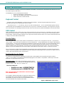
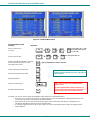
Enabling the Security Feature
To enable the security feature the administrator must first enter Command Mode from the keyboard using the sequence
<Ctrl> + <`> (accent key). The OSD menu will automatically appear on the monitor. This provides a visual way to control the
NODEMUX using the keyboard and mouse.
The administrator
, when setting the NODEMUX switch up for the
first time, may want to proceed directly to the ADMINISTRATION Mode
by typing <CTRL> +<M> , then <A>, and then <Y>.
The factory settings are:
• default user name = ADMINISTRATOR
• default password = ADMINISTRATOR
Note: The user name for the administrator cannot be changed
from "ADMINISTRATOR".
Once logged-in, follow the instructions on page 10 for setting up users
and changing the password. Within the Administration Mode the
administrator can setup each of the users and the limitations of their
use of the individual CPUs attached to the switch.
Figure 5- Administrator Login screen

NTI RACKMUX KVM Drawer with NODEMUX Switch
8
When a standard user powers up the system a security screen will appear if security has been enabled by the
administrator. The user will need to login to the switch by following the instructions below for the USER LOGIN. If the user
does not know the appropriate user name and password (setup by the administrator), contact the switch administrator for this
information. Once logged-in a user can follow the Command Mode functions described on page 9 to control the switch within the
limitations as determined by the administrator.
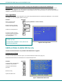
User Login Mode
User login mode requires a user to login with a user name and password from the list created by the administrator. This mode will
also disable use of the front panel until the user logs in.
Function: Keystroke:
Adds a character to the
user name/password
Removes previous character
from the user name/password
Submit user name/password
Exit USER LOGIN and return
to previous mode. This function
is only available if security is
not currently active.
Figure 6- User Login screen
Additional Modes Available With Security
The three modes that follow are only available if the administrator is logged in.
Administration Mode
To enter the Administration Mode menu press <A> from the Maintenance Mode menu (page 15).
Administration Mode allows the administrator to use the following functions:
Function: Keystroke:
Configure switch- for application
and RS232 communication
Change the administrator’s
password
Disable security
Update User Name List
Figure 7- Administration Mode menu
Esc
Enter
A-Z
0-9
(Type any alphabetical or numeric character)
Backspace
If the password submitted is incorrect, the user will not
be able to proceed.
If the password submitted is correct, the user will
proceed to Normal Mode.
S
C
U
W

NTI RACKMUX KVM Drawer with NODEMUX Switch
9
Administration Mode (Cont'd)
Function: Keystroke:
Selects the idle time in minutes
Exit Administration Mode and
return to previous mode
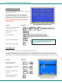
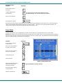
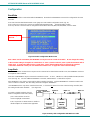
Switch Configuration
Switch Configuration enables the administrator to configure the NODEMUX to be used as a stand alone switch or as one of the
switches in a cascaded system. Switch Configuration is also used to setup the communication settings for RS232
communication with a remotely connected terminal through the RS232 port.
Note: When used in a RACKMUX, the NODEMUX can only be used as a stand alone switch. Do not change this setting.
In the event the setting is changed from "stand alone" to "slave", when the switch is power cycled the OSD menu will
no longer work. To change it back to a "stand alone" switch, factory default settings must be restored via a terminal
connected to the RS232 control port. See RS232 Control on page 16 for how to restore default settings.
Figure 8- Switch Configuration Mode screen
For more on configuring RS232 control, see "RS232 Control" on page 16.
Exit Switch Configuration Mode
Once changes are made to the Switch Configuration menu, press <Enter> and <Y> to save them.
To exit without saving
, press <Esc>, then <N>, then <Esc> again. The menu will return to the Administration Mode without
saving the changes made. .
Changes made will take effect the next time the NODEMUX is power cycled.
Esc
T
-
-
(xxx from 000 to 255. i.e. T002
would set the time-out period
for 2 minutes. 000 will disable it)
-
(0-2)
x
(0-9)
x
(0-9)
x
Do not change
this field.

NTI RACKMUX KVM Drawer with NODEMUX Switch
10
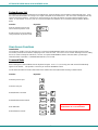
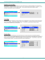
Administrator Password
To change the administrator password press <C> from the
Administration Mode menu.
The administrator is able to change the administrator
password as needed (see Fig. 9). Two edit fields are
available, one for password, the other for verify password.
The password can be up to 13 characters in length.
Note: The default password for the administrator is
ADMINISTRATOR.
Figure 9- Administrator password change
Function: Keystroke:
Add character to password string
or verify password string
Delete previous character in
edited string
Save new password.
Move to next field to be edited
Return to Administration Mode
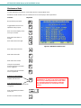
User Name List
To enter the User Name List press <U> from the Administration Mode menu.
The User Name List displays the list of users and provides control for adding new users (up to 63), changing or assigning user
passwords, and changing access rights for any given user. User names may be up to 12 characters long, may not contain
spaces, and are not case sensitive. Passwords may be up to 15 characters long, may not contain spaces, and are case sensitive.
Function: Keystroke:
Edit the highlighted user’s
System Access rights
Enter Edit Mode to add/change/
remove users
Change the highlighted user’s
password
Exit the User Name List and
return to previous mode
Figure 10- User Name List screen
Esc
Enter
(If Password string and Verify Password string
are different, this command will have no effect,
enabling the administrator to correct the password)
Backspace
Shift
or
A-Z
(Type any upper or lower case
alphabetical or numeric character)
+
A-Z
0-9
Tab
FYI: Once the password is setup, if the password
is lost of forgotten, see page 28 for instruction on
how to reset the password to the default
password.
Esc
E
Ctrl
+
A
Ctrl
+
P
Ctrl
+

NTI RACKMUX KVM Drawer with NODEMUX Switch
11
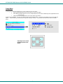
System Access List
The System Access List (accessible from the User Name List- page 10) displays a list of numbers representing the ports. From
this screen the administrator can change access rights to the ports for the selected user. The user’s name is displayed at the top
of the access list for reference. The mouse is used to change access rights by clicking on a given number to toggle a port’s
status. A user that has access to a port can connect to that port and control the CPU connected to that port when in Normal
Mode.
Function: Keystroke:
Save the changes to the access
list and return to previous mode
Exit the System access list without
saving and return to previous mode.
User Access Functions
Introduction
The OSD menu enables a user to name the CPUs connected to the NODEMUX switch and connect to them using that name.
The OSD is positioned on the monitor, displaying 8 CPU names at a time. The screen can be used for switching as well as editing
the CPUs’ names. Through the OSD menu, the user can operate the NODEMUX switch to have the switch cycle through 3
extended modes of operation: COMMAND, BROADCAST, and SCAN .
Command Mode
When entering the Command Mode from the keyboard using the <Ctrl> + <`> (accent key), the OSD menu will automatically
appear on the monitor. This provides a visual way to control the NODEMUX switch.
The list below describes the OSD Command functions available from the keyboard after entering Command Mode:
Function: Keystroke:
Select the previous port
Select the next port
Enable/disable Scan Mode
Enable/disable Broadcast Mode
Enter Edit Mode
Enter Maintenance Mode
S
Ctrl
+
E
Ctrl
+
M
Ctrl
+
B
Ctrl
+
Esc
Enter
Note: The user must be logged in as
administrator to access Edit Mode

NTI RACKMUX KVM Drawer with NODEMUX Switch
12
Figure 11- Command Mode menus
Command Mode (Cont'd)
Function: Keystroke:
Sets scan time-out on
each port
Selects a specific port
Enters Search Mode and adds a character
to search string and selects the CPU’s
name that matches best.
Selects the first port on the switch
Selects the last port on the switch
Display Help Menu
Switch to a selected port
Exit OSD Command Mode
The mouse can also be used to control the NODEMUX switch within the Command Mode menu.
• The mouse cursor can be moved to the Scan, Help, Broadcast, Timeout, Maintenance and Exit fields where the user
can then click on the left mouse button to perform that function.
• Ports listed on the screen can be selected by moving the cursor onto that port and clicking. Clicking twice on a
selected port will switch to that port and exit Command Mode.
• To change the displayed ports on the screen simply click on the up and down arrows located to the right of the port
names displayed.
F1
End
Enter
Home
Esc
A-Z
0-9
(Type any alphabetical or numeric character)
Press <CTRL> while in the Command Mode menu
to display the Edit, Maintenance, Port, and Timeout
control features.
Note: The user must exit Command Mode to
type to a CPU.
To exit Command Mode, either hold down any
touch-switch on the front panel for more than 2
seconds, OR press <ESC> on the keyboard.
P
-
-
(Pxx would be P01, P02, etc.)
(0-9)
x
(0-9)
x
Ctrl
+
T
-
-
(xxx from 002 to 255. ie. t002
would set the time-out period
for 2 seconds)
-
(0-2)
x
(0-9)
x
(0-9)
x
Ctrl
+

NTI RACKMUX KVM Drawer with NODEMUX Switch
13
Broadcast Mode
To activate Broadcast Mode press <Ctrl> + <B> from the Command Mode menu.
(use with extreme caution or commands intended for one CPU will be sent to all CPUs)
Broadcast Mode allows the operator to send keystrokes to all active CPUs simultaneously (even those CPUs the user cannot
connect to due to lack of security access).
However, Broadcast Mode has some critical requirements:
• BROADCAST mode must be OFF when booting any attached CPUs.
• BROADCAST mode must be ON and COMMAND MODE must be OFF for keystrokes to reach attached CPUs.
NOTE: The user must type somewhat slowly when in Broadcast Mode (less than 20 wpm) and cannot use the
<Backspace> key.
Broadcast Mode is not supported by any ports that have MAC CPUs attached.
Scan Mode
To activate Scan Mode press <Ctrl> + <S> from the Command Mode menu.
When in Scan Mode the switch scans to each port with a CPU powered-ON. The port with the CPU powered-ON remains active
while in use. When the switch becomes idle for the configured time-out period (default time-out period is 5 seconds) the switch will
connect to the next powered-ON CPU port. See Command Mode section (page 11) for configuring the scan time-out period for
each port.
Note: The keyboard and mouse must remain idle for the full scan dwell time before the switch selects the next active
port.
Note: The scan dwell time set by the user only effects that user and has no effect on other switch users.
Normal Mode
When the NODEMUX switch is not in Command, Broadcast, or Scan mode, the user is in Normal Mode, controlling the CPU to
which the user is connected through the NODEMUX switch.
Edit Mode
To activate Edit Mode press <Ctrl> + <E> from the Command Mode menu.
Edit Mode enables the user to modify the names of the CPUs connected to the switch. Names of CPUs can be up to 12
characters in length. When in Edit Mode, multiple keystroke combinations are not valid (<Shift>+P, <Ctrl>+P, <Alt>+ P, and P will
all type a “P” to the display - lower case letters cannot be typed).
Function: Keystroke:
Move cursor one position
to the right
Move cursor one position
to the left
Move cursor to the
previous port
Move cursor to the
next port
Selects the first port on
the switch
Figure 12- Edit Mode screen
Home

NTI RACKMUX KVM Drawer with NODEMUX Switch
14
Edit Mode (Con'td)
Function: Keystroke:
Selects the last port on
the switch
Toggles between insert
and overstrike
Erase current character
Erase previous character
When finished making changes in Edit Mode, press <Enter> and a prompt will appear to press either <Y> to save the changes or
<N> to continue making changes without saving the changes just made. If the <Esc> key is pressed instead of <Enter>, all
changes made will be ignored and the display will return to the previous menu.
Search Mode
To enter Search Mode, type any alphabetical or numeric character when the Command Mode menu is on the monitor.
Search Mode enables the user to enter and maneuver through a list of CPU names. The CPU name best matching the characters
typed is selected. The list of CPUs may also be searched for a specific (or similar) name. The following commands are valid when
the search option has been invoked from Command Mode.
Function: Keystroke:
Erase previous character
in search name
Move cursor one position to
the right in search name
Move cursor one position to
the left in search name
Select previous port
Select next port
Figure 13- Search Mode screen
Add a character to the search
string and select the best
matching CPU name
Exit Search Mode, return to
Command Mode
Switch to selected port
Insert
(The character either gets inserted and the remainder of the name
gets shifted to the right, OR the current character gets overwritten.)
Delete
Backspace
Backspace
End
A-Z
0-9
(Type any alphabetical or numeric character)
Esc
Enter

NTI RACKMUX KVM Drawer with NODEMUX Switch
15
Maintenance Mode
To enter Maintenance Mode press <Ctrl>+<M> from the Command Mode menu.
Maintenance Mode enables a user to customize the On Screen Display to their requirements.
Function: Keystroke:
Reset all of the port names
Toggle between numeric and
alphabetic listing of ports
Move On Screen Display (OSD)
menu up on monitor
Move OSD menu down on
monitor
Move OSD menu to the right
Figure 14- Maintenance Mode screen
Move OSD menu to the left
Make OSD menu taller
Make OSD menu shorter
Change user password.
(Present only when a standard
user is logged in.)
Log current user out and return
to User Login Mode.
Activate security features
.
Present only when security is
available but not active.
Enter Administration Mode.
Option present only when Administrator
is logged in.
Save OSD window parameters
for the port
Return to Command Mode
R
L
T
S
P
Q
A
Esc
Enter
Note: If activating security features, the user will be
prompted for a “Y” (yes) or “N” (no) to confirm the
menu choice, at which point the user will be asked
for a username and password before continuing.
Only the administrator can activate the security
features.

NTI RACKMUX KVM Drawer with NODEMUX Switch
16
Help Mode
To enter Help Mode press the <F1> key from the Command Mode menu (page 11).
Help Mode displays a list of commands with a short explanation of their function. These lists are organized in pages for each
mode (i.e. COMMAND, EDIT, and SEARCH). The following options enable the user to quickly obtain information on any
command
.
Function: Keystroke:
View the previous page of help
if available
View the next page of help
if available
Exit HELP and return to previous
mode
RS232 CONTROL
The NODEMUX can be configured to be controlled by a remote terminal connected through the RS232 port at the rear of the
NODEMUX. For RS232 communication with a remote terminal to work, the NODEMUX must first be configured for the baud rate
and address.
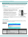
RS232 Connections and Configuration
Remote Connection
The RS232 Interface is designed to meet the RS232C standard and can be controlled from any CPU or other controller with an
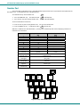
RS232 communications port. The pin-out for the DB-9 connector on the unit is as follows:
RS232 Connector (DB-9 FEMALE)
PIN SIGNAL FUNCTION
1 CD Carrier Detect
2 TXD Transmit data (RXD at host)
3 RXD Receive data (TXD at host)
4 DTR Data terminal ready
5 GND Signal ground
6 DSR Data set ready
7 RTS Request to send
8 CTS Clear to send
9 - No connection
On the DB-9 female connector, pins 1 (DCD), 4 (DTR), and 6 (DSR) are shorted and pins 7 (RTS) and 8 (CTS) are shorted.
Therefore, host handshaking is bypassed and TXD and RXD are the only active signals. A straight through DB-9 cable (not null
modem) will work for most CPUs. To daisy chain multiple units, a Matrix Y-1 cable is used (see page 17) for each NODEMUX in
the chain.
Esc
Page
Down
Page
Up
Note: Security must be disabled or user access
granted on the port(s) to be selected by RS-232
control.
Page is loading ...
Page is loading ...
Page is loading ...
Page is loading ...
Page is loading ...
Page is loading ...
Page is loading ...
Page is loading ...
Page is loading ...
Page is loading ...
Page is loading ...
Page is loading ...
Page is loading ...
Page is loading ...
Page is loading ...
-
 1
1
-
 2
2
-
 3
3
-
 4
4
-
 5
5
-
 6
6
-
 7
7
-
 8
8
-
 9
9
-
 10
10
-
 11
11
-
 12
12
-
 13
13
-
 14
14
-
 15
15
-
 16
16
-
 17
17
-
 18
18
-
 19
19
-
 20
20
-
 21
21
-
 22
22
-
 23
23
-
 24
24
-
 25
25
-
 26
26
-
 27
27
-
 28
28
-
 29
29
-
 30
30
-
 31
31
-
 32
32
-
 33
33
-
 34
34
-
 35
35


NTI RACKMUX-V17-4UNV User manual
- Category
- Rack consoles
- Type
- User manual
- This manual is also suitable for
Ask a question and I''ll find the answer in the document
Finding information in a document is now easier with AI
Related papers
-
 NTI RACKMUX-D17HR-N-SUSBHD4 Installation guide
-
 NTI RACKMUX-T15-N-Sx Quick Start Setup Manual
-
NTI ENVIROMUX Series Installation guide
-
NTI XTENDEX Series Installation guide
-
 NTI USB-SUN-R User manual
-
 NTI ST-2C5VA-L-600 Operating instructions
-
-
 NTI KEEMUX-USBV-2U Installation & User Manual
-
 NTI XTENDEX VOPEX-C5SV-x User manual
-
 NTI ST-C5USBVA-300 User manual


Other documents
-
 Network Technologies ST-nXm-U User manual
-
 Cables Direct EX-665 Datasheet
-
 Network Technologies MAN015 User manual
-
 Network Technologies ST-2U User manual
-
 Network Technologies RACKMUX Series User manual
-
 Video Products USB-SUN User manual
-
 Network Technologies ST-xU User manual
-
 SharkRack Switch KVM-8 User manual
-
 Network Technologies 2907 User manual
-
 Network Technologies Switch ST-C5KVM-600-CE User manual


