Page is loading ...

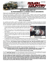
84-01 6.5” XJ CHEROKEE LIFT KIT
Thank you for choosing Rough Country for your suspension needs.
Rough Country recommends a certified technician installs this system. In addition to these instructions, professional
knowledge of disassemble/reassembly procedures as well as post installation checks must be known. Attempts to install
this system without this knowledge and expertise may jeopardize the integrity and/or operating safety of the vehicle.
Please read all the instructions before beginning the installation. Check the kit hardware against the parts list. Be sure
you have all the needed parts and understand where they go. Also please review the tools needed and make sure you
are confident about undertaking this installation. If you have any questions about the installation of this kit, call Rough
Country at 800-222-7023.
PRODUCT USE INFORMATION
As a general rule, the taller a vehicle is the easier it will roll. We strongly recommend, because of roll-
over possibility, that the vehicle be equipped with a functional roll-bar and cage system. Seat belts and shoulder
harnesses should be worn at all times. Avoid situations where a side rollover may occur.
Braking performance and capabilities are decreased when significantly larger/heaver tires and wheels are used. Take
this into consideration while driving. Also, speedometer recalibration is necessary when larger tires are installed.
Do not add, alter, or fabricate any factory or after-market parts which increase vehicle height over the intended height of
the Rough Country product purchased. Mixing component brands, lifts, voids all warranties. Rough Country makes no
claims regarding lifting devices and excludes any and all implied claims. We will not be responsible for any product that
is altered.
This kit features Rough Country’s adjustable joint design. Adjustable end tool is included in kit.
Assemble the joints per the separate instruction sheet Part # 92RCJ120 provided
The 6.5” suspension system was developed for 33x11.50x15 tire on 15 x 8 after market wheel with 3.75” of back spac-
ing. This tire size may require the installation of aftermarket flares and due to variation in vehicles when manufactured
and the numerous options available, the amount of actual lift gained by this lift kit will vary. On models outfitted with ex-
tra bolt-on equipment and accessories, Rough Country offers new coil spring isolator pads made from polyurethane to
boost ride height 3/4". NOTICE TO DEALER AND VECHICLE OWNER
Any vehicle equipped with any Rough country product must have the “Warning to Driver” decal installed on the sun visor
or dash. The decal is to act as a constant reminder for whoever is operating the vehicle of its unique handling character-
istics. INSTALLING DEALER—It is your responsibility to install the warning decal and to forward these installation in-
structions on too the vehicle owner for review and to be kept in the vehicle for its service life.
92169600
Spring Compressor
Pitman Arm Puller
Silicone Spray
½” Drill
Drill Assortment (1/8” to 1/2")
Torque Wrench
Hammer
½” Drive Ratchet and Sockets
Combination Wrenches
Allen Wrenches
Torx Key Socket
Tape Measure
File
Large “C” Clamps and/or Bench Vise
Hydraulic Floor Jacks
Heavy Duty Jack Stands
Wheel Chocks (Wooden Blocks)
Grease or Anti Seize Compound
TOOLS NEEDED:
If question exist we will be happy to answer any questions concerning the design, function, and correct use of our prod-
ucts. Please call us at 800-222-7023. The required installation time for this kit is 6-8 hours.

KIT CONTENT
Rear Leaf Springs—2
Frt Coil Springs—2
Frt Adj Track Bar
Transfer Case Spacers
Sway Bar
Disconnects 2
Upper Adj
Control Arms (2)
Lwr Adj
Ctrl Arms 2
Rear Adj
Shackles 2
Pitman Arm
Front
Shocks(2)
Rear
Shocks (2)
U bolts
Brake Reloc Brkts
Kit Includes:
8047-Rear Springs
1042- Forged Adj Track Rod
1696N2-Shock Absorbers:
Front Shock # 658693
Rear Shock # 658708
9275-Front Coil Springs
1696 Kit Box Including:
Rear Lifted Shackles (2)
Front Upr Adj Control Arms (2)
Front Lwr Adj Control Arms (2)
Front Disconnect Assemblies (2)
Front Disconnect Bracket (2)
Pitman Arm
Front Brake Line Brackets (2)
Rear Components:
Rear Brake Line Bracket
Rear U-bolts (4)
Transfer Case Drop Spacers (4)
For Rear Shackle:
Bushings (4)
Sleeves (2)
9/16” x 4” Bolts (2)
9/16” Lock Nuts (2)
14mm x 110mm Bolts (2)
14mm Lock Nuts (2)
Flat Washers (8)
For Transfer Case Spacers:
10mm x 60mm Bolts (4)
For Front & Rear Brake Line Brackets:
5/16” X 3/4” Bolts (3)
5/16” Lock Nuts (3)
5/16” Flat Washers (3)
For Pitman Arm:
Cotter Pin
For Sway Bar Bracket:
3/8” x 1 1/4” Bolt (2)
3/8” Flange Lock nut (2)
3/8” Flat Washers (2)
For Sway Bar Disconnects:
5/16” x 1” Tap Bolts (4)
3/8” x 1 1/4” Bolts (2)
Thick Washers (2)
Disconnect Pins (2)
Hitch pins (2)
Rod Ends (2)
1/2” Nuts (2)
1/2” Flat Washer (2)
1/2” Flange Lock Nut (2)
1/2” Jam Nut (2)
For Adjustable Track Bar:
Bushings (2)
Sleeve
Tie-Rod End
Jam Nut
Cotter Pin
Track Bar Brkt

PRE-INSTALLATION INSTRUCTIONS
1. Layout the product – see page 7 for product layout and confirm that you have all needed products and know where
they install.
2. Pre-assemble both lower control arms by putting the bushings and sleeves in each end. Grease the bushings with
waterproof (lithium based) grease to prevent squeaking.
3. Verify before installation rear axle tube diameter is 2 ¾” or 3”. Both sets are included with this kit to accommodate
rear axle options of the vehicle.
INSTALLATION INSTRUCTIONS
1. Secure and properly block the tires on the vehicle on a level concrete surface.
2. Jack up the vehicle and place the front of the vehicle on jack stands.
3. Remove the front wheels and tires.
4. Support the axle with a floor jack.
5. Remove the stock shock absorbers using a 15mm wrench. The stock bolts and nuts on the bottom of the shock will
be reused. Note: Access to the upper shock studs will be obtained through the engine compartment. It also may be
necessary to temporarily remove the washer fluid reservoir to access the driver side upper shock mount nut.
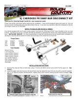
6. Remove the sway bar links on both sides using a T-55 torx bit /19mm wrench and a 15mm for the upper nut . SEE
PHOTO 1.
7. Remove the track bar from the axle housing on passenger side using a 15mm wrench. SEE PHOTO 2. Retain fac-
tory bolt and flag nut for re-use.
8. Locate and remove the coil clip on the driver side lower coil spring seat using a 13mm wrench. Lower the axle to
allow for removal of the coil spring. Do not overextend the brake lines. The caliper can be removed from the rotor to
allow the axle to lower. Do not let the brake caliper hang from the brake line. Remove coil spring. SEE PHOTO 3.
Repeat for opposite side.
9. With the differential supported, remove the driver side lower control arm from the vehicle using a 21mm wrench.
SEE PHOTO 4. Retain factory hardware, as it will be reused. Repeat for opposite side.
10. Lower the axle using the floor jack. With the axle lowered, install coil springs on both sides, making sure the lower
coil wrap is seated in the lower spring cup. Install factory spring retainer and secure with factory hardware using a
13mm wrench.
PHOTO 2
PHOTO 3 PHOTO 4
PHOTO 1

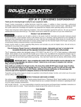
11. Adjust new lower control arm to 16.5” from center to center and install using factory hardware. SEE PHOTO 5.
12. Remove the stock upper control arm by removing the factory hardware from the axle bracket and then removing the
nut and bolt from the frame bracket doing one side at a time. Do not remove the factory bushing in the axle mount –it
is reused. Lubricate bushings with a lithium grease or equivalent and install the new bushings and sleeves in the
Rough Country control arm. Adjust the upper Rough Country adjustable control arm to a measurement of 15 ½”
from center to center and install on the vehicle using factory hardware – do not tighten at this time. SEE PHOTO 6.
12. PHOTO 7 shows the caster adjustment bolts on the lower control arms. These bolts can be adjusted in or out if
needed for additional caster alignment. Final alignment should be performed by a professional.
13. Install the Rough Country adjustable track rod in the factory location axle mount using factory hardware. Do not at-
tach the frame end of the new track rod at this time. Installation is done after the vehicle is on the ground and axle is
centered. SEE PHOTO 8.
14. Install the new shock absorbers Part # 658562 and tighten the factory bottom bolts using a 13mm wrench and the
upper with a 9/16 wrench . Reinstall the wiper reservoir if removed.
15. Install the front wheels and tires. Jack up the vehicle, Remove jack stands and lower the vehicle to the ground.
16. Check to make sure the body is centered over the axle. Unlocking the steering wheel and turning the wheel to move
the body, do this until the track rod hole lines up. Install the track rod with the stock bolt /flag nut and using a 15mm
wrench. Torque to factory specs.
**Control Arm Note** Make sure flex joint housing is centered in mount before tightening jam nut. Should
not be touching either side.**
PHOTO 7
PHOTO 6
PHOTO 8
PHOTO 5

FRONT SWAY BAR DISCONNECT INSTRUCTIONS
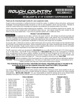
1. Install the upper sway bar mount on the top of front sway bar where the stock link was secured, using the supplied
3/8” x 1.25” bolt lock washer and thick washer. See Photo 1.
2. Using a hammer, remove the lower stock sway bar link mounting bolt from the axle mount.
3. Install supplied pin on the axle. See Photo 2. Hold using a screwdriver & tighten 1/2” lock nut using a 3/4” wrench.
4. Assemble the sway bar link with the link body, the jam nut and rod end Adjust the sway bar to a length of 11 1/4”
from top to bottom. Tighten the jam nut against the rod end using a 5/8” & 3/4” wrench.
5. Install the sway bar link on the upper sway bar mount with the supplied 1/2” flange lock nut. See Photo 3. Tighten
using a 5/8” & 3/4” wrench.
6. With the sway bar link installed on the supplied frame bracket, swing the bracket and sway bar link up and position
the bracket on the frame as shown in Photo 4.
7. While holding the bracket in place, remove the sway bar link from the bracket. Mark and drill the holes using a 1/4”
drill bit.
8. Install the supplied 5/16” x 1” self tapping bolt in the drilled holes and tighten using a 1/2” socket. See Photo 5. Do
not over tighten the self tapping bolts.
9. Install on the lower axle mounting pin. Install the disconnect pin. See Photo 6. Note: When disconnected the
hitch pin will be used on the upper mount to secure the sway bar link to the mount.
PHOTO 2
PHOTO 29
PHOTO 3
PHOTO 6
Install the sway bar link on the axle with hitch pin
PHOTO 4
PHOTO 5
Install the pin on the axle
Install the link on the mount Place the mount on the uni-body
PHOTO 1
Install mount using thick washer

FRONT BRAKE LINE BRACKET INSTALLATION
1. Remove the front brake line from the frame using a T-40 Torx
bit.
2. Attach the brake line to the new brake line extension bracket
with l the supplied 5/16” hardware as shown in PHOTO 1 and
tighten using a 1/2” wrench.
3. Install the new bracket into the stock hole with the stock hard-
ware using the T-40 bit.
PITMAN ARM INSTALLATION
1. Remove the cotter pin and nut that secures the steering link to
the arm. Retain the nut to be reused. Separate the drag link
ball stud from the pitman arm with a puller tool. Do not use a
pickle fork.
2. Mark the position of the original pitman arm. Remove the nut
and washer from the steering gear box. Align and install new
pitman arm on the steering gear shaft. Install the washer and
nut. Tighten to 185 ft. lbs.
3. Install the drag link ball stud to the pitman arm. Install the nut
and tighten to 60 ft lbs. Install supplied cotter pin. SEE PHOTO
2.
REAR LIFT INSTALLATION
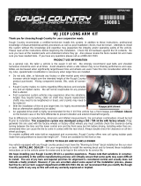
1. Remove rear factory shocks using a 13mm wrench on top and
a 3/4” wrench on bottom and retain hardware.
2. Chock the front wheels and jack up the rear of the vehicle and
place the vehicle on jack stands. Remove the wheels and tires.
3. Working from the drivers side, remove the factory u-bolts and lower the axle with a floor jack. Repeat for passenger
side. Install new rear springs at this time with factory hardware using 21mm wrench and skip to Step 10. The larger
spring eye will bolt back in the stationary mount.
4. Remove the stock shackle from the frame mount using a 21mm wrench. SEE PHOTO 3. Locate and either grind or
cut off the excess from the bolt pictured in PHOTO 4. This will allow the shackle to move rearward.
5. Install the new Rough Country lifted shackle and secure with
supplied 9/16” x 4” hardware in the top hole and the 14mm x
110mm in the bottom hole.. Do not fully tighten the hardware at
this time. See PHOTO 5.
6. This kit includes 2 3/4” & 3” diameter u-bolts for rear axle op-
tions on the Jeep. Confirm axle diameter and use appropriate u
-bolt. Install the u-bolts and torque to factory specs using 3/4”
wrench.
7. Install the new shocks Part # 650328 with factory hardware.
Torque the upper using a 13mm wrench and lower bolts using
3/4” wrench to factory specs. Repeat for other side.
8. Install the tires and wheels. Jack up the vehicle and remove
the jack stands. Lower the vehicle to the floor.
9. Torque the frame bolts, and shackle bolts to factory specs us-
ing a 21mm wrench.
PHOTO 3
PHOTO 1
PHOTO 5
PHOTO 2
PHOTO 4

REAR BRAKE LINE INSTALLATION INSTRUCTIONS
1. Next remove the E-clip holding the brake line on at the
frame mount. This will be extended with a bracket.
2. Bolt the z drop bracket to the frame using the supplied
5/16” hardware and tighten using a 1/2” wrench. Install
the brake line into the new bracket with the stock e-clip.
SEE PHOTO 1.
TRANSFER CASE DROP INSTALLATION INSTRUCTIONS
1. Position the floor jack under the transfer case cross mem-
ber and lightly apply pressure.
2. Loosen and remove the bolt and the nut on stud on the
driver side transfer case cross member.
3. Loosen and remove the bolt and nut on the drivers side cross member.
4. Carefully lower the transfer case down to the point it clears
the stud.
5. Using 2 nuts to form a jam nut on the stud, remove the
stud from the cross member on both sides.
6. Carefully lower the transfer case cross member to allow
clearance for installation of transfer case spacer and
sleeve.
7. Place the spacer between the frame and cross member;
install the new 10mm x 60m bolts through cross member,
spacer and into uni-body. Raise the transfer case and
tighten bolts to 35 ft/lbs. See PHOTO 2.
PHOTO 1
Driver Side Frame Rail Shown
PHOTO 2
POST INSTALLATION INSTRUCTIONS
1. Check all fasteners for proper torque.
2. Check to ensure there is adequate clearance between all rotating, mobile, fixed and heated members.
3. Check steering gear for interference and proper working order.
4. Before driving the vehicle, check to make sure brakes are operating properly and do not need to be blead.
5. Perform steering sweep.
6. Check to ensure brake hoses have sufficient slack and will not contact rotating, mobile, or fixed members. Adjust
lines/brackets to eliminate interference and maintain proper working order. Failure to perform inspections may result
in component failure.
7. Have headlight readjusted to proper settings.
8. Take the vehicle to be aligned to factory specifications by a certified alignment shop.
9. Re torque all fasteners after 500 miles. Visually inspect components and re torque fasteners during routine vehicle
service.
MAINTENANCE INFORMATION
It is the ultimate buyers responsibility to have all bolts/nuts checked for tightness after the first 100 miles and then
every 100 miles. A qualified mechanic must inspect wheel alignment steering system, suspension and driveline systems
at least every 3000 miles.

Thank you for purchasing a Rough Country Suspension System.
We have most of the additional accessories you need for your Cherokee. We have Rock Sliders, Diff
Guards, Slip Yoke Eliminator, Drive Shafts, Steering Stabilizers, Adjustable Controls Arms, Etc.
$49.95
Stabilizer
Drive-Shafts
Call For Price$
$269.00
SYE Kits
By purchasing any item sold by Rough Country, LLC, the buyer expressly warrants that he/she is in compliance with all
applicable , State, and Local laws and regulations regarding the purchase, ownership, and use of the
item. It shall be the buyers responsibility to comply with all Federal, State and Local laws governing
the sales of any items listed, illustrated or sold. The buyer expressly agrees to indemnify and hold
harmless Rough Country, LLC for all claims resulting directly or indirectly from the purchase, owner-
ship, or use of the items.
/