Page is loading ...

84-01 4.5” & 6”XJ CHEROKEE LONG ARM KIT
Thank you for choosing Rough Country for your suspension needs.
Rough Country recommends a certified technician installs this system. In addition to these instructions, professional
knowledge of disassemble/reassembly procedures as well as post installation checks must be known. Attempts to install
this system without this knowledge and expertise may jeopardize the integrity and/or operating safety of the vehicle.
Please read all the instructions before beginning the installation. Check the kit hardware against the parts list. Be sure
you have all the needed parts and understand where they go. Also please review the tools needed and make sure you
are confident about undertaking this installation. If you have any questions about the installation of this kit, call Rough
Country at 731-285-9000.
PRODUCT USE INFORMATION
As a general rule, the taller a vehicle is the easier it will roll. We strongly recommend that seat belts and shoulder
harnesses should be worn at all times. Avoid situations where a side rollover may occur.
Braking performance and capabilities are decreased when significantly larger/heaver tires and wheels are used. Take
this into consideration while driving. Also, speedometer recalibration is necessary when larger tires are installed.
Do not add, alter, or fabricate any factory or after-market parts which increase vehicle height over the intended height of
the Rough Country product purchased. Mixing component brands, lifts, voids all warranties. Rough Country makes no
claims regarding lifting devices and excludes any and all implied claims. We will not be responsible for any product that
is altered.
The 4.5” Long Arm Kit system was developed for 32x11.50x15 tire on 15 x 8 after market wheel with 3.75” of back spac-
ing. The 6” kit was developed for 33x12.50x15 tire on 15 x 8 after market wheel with 3.75” of back spacing. Due to the
inconsistency of vehicles when manufactured and the various options available, the amount of actual lift gained by this
lift kit will vary. On models outfitted with extra bolt-on equipment and accessories, Rough Country offers new coil spring
isolator pads made from polyurethane to boost ride height 3/4".
Please verify before installation rear axle tube diameter is 2 1/2” or 3”. Both sets are included with this kit to accommo-
date rear axle options of the vehicle.
This kit features Rough Country’s adjustable joint design. Adjustable end tool is included in kit.
Assemble the joints per the separate instruction sheet Part # 92RCJ120 provided
NOTICE TO DEALER AND VECHICLE OWNER
Any vehicle equipped with any Rough country product must have the “Warning to Driver” decal installed on the sun visor
or dash. The decal is to act as a constant reminder for whoever is operating the vehicle of its unique handling character-
istics. INSTALLING DEALER—It is your responsibility to install the warning decal and to forward these installation in-
structions on too the vehicle owner for review and to be kept in the vehicle for its service life.
92PERF1689
Jack Stands
Floor Jack
Transmission Jack or comparable jack
Wheel Chocks
T-55 Torque Bit
T-30 Torque Bit
13mm Socket / Wrench
14mm Socket / Wrench
15mm Socket / Wrench
17mm Socket / Wrench
18mm Socket / Wrench
19mm Socket / Wrench
21mm Socket / Wrench
1/2” Socket / Wrench
9/16” Socket / Wrench
3/4” Socket / Wrench
1 1/8’ Wrench
17/32” Drill Bit
25/32” Drill Bit
23/64” Drill Bit
Drill Motor
Torque Wrench
Brake Fluid
Catch Pan
TOOLS NEEDED: Torque Specs:
Size Grade 5 Grade 8
5/16” 15 ft/lbs 20 ft/lbs
3/8” 30 ft/lbs 35 ft/lbs
7/16” 45 ft/lbs 60 ft/lbs
1/2” 65 ft/lbs 90 ft/lbs
9/16” 95 ft/lbs 130 ft/lbs
5/8” 135 ft/lbs 175 ft/lbs
3/4” 185 ft/lbs 280 ft/lbs
Class 8.8 Class 10.9
12MM 55ft/lbs 75ft/lbs
14MM 85ft/lbs 120ft/lbs
16MM 130ft/lbs 165ft/lbs
18MM 170ft/lbs 240ft/lbs

9278-4” Front Coil Springs
OR
9275-6” Front Coil Springs
1689Box1 OR 1601Box1 (2.8L Engine)
Dr Lower Long Arm& Joint (A)
Pass Lower Long Arm& Joint (B)
Dr Upper Arm (C)
Pass Upper Arm (D)
Cross member Side Plates (E)
Pitman Arm (F)
1/2” Flag Nut-For Frt Crssmbr (2)
1689Box2-For NP231 Transfer Case
Transfer Case Skid Plate (G)
OR
1616Box1-For NP242 Transfer Case
Transfer Case Skid Plate (G)
1689Box3
Long Arm Cross-member (H)
1689Box4
Fr Sway Bar Disconnects (I)
Fr Stainless Steel Brake Lines (J)
U-Bolts (2 3/4” x 6 3/4” or 3” x 8”)
For either axle size
Rear Stainless Steel Brake Line
1079 Adjustable Track Bar Kit
Front Adjustable Track Bar (K)
Track Bar Bracket (L)
Perf2.2Shocks:
Fr RCX 2.2 Series Shocks (M)
RR RCX 2.2 Series Shocks (N)
Lift Options for 4” Kit
Lifted Shackles (1077) (O)
& Add-a-Leaf (6123) (P)
OR
Lifted Springs
Lift Contents for rear of 6” Kit:
Rear Leaf Springs
& Shackles (1077)
Fasteners List:
1689Bag1-In 1689Box1 /1601Box1
For Front Cross member
10mm x 35mm Bolt (6)
10mm Flat Washer (6)
Crush Sleeve (2)
1/2” x 4 1/2” Bolt (2)
1/2” Flat Washer (6)
1/2” Lock nut
For Front Lower Control Arms
9/16’ X 4” Bolt (2)
9/16” Flat Washer (4)
9/16” Lock Nut (2)
For Front Upper Control Arms
10mm x 80mm Bolt (4)
10mm Lock Nut (4)
10mm Flat Washer (8)
For Transfer Case Skid Plate
3/8” x 1” Bolt (2)
3/8” Flat Washer (2)
3/8” Lock Washer (2)
3/8” Self Tapping Bolt (2)
1689Bag2– In 1689Box4
For Fr Sway Bar Disconnect:
4-5/16” x 1” Self Tap Bolts
2-3/8” x 1 1/4” Bolts
2-Thick Washers
2-Disconnect Pins
2-Hitch pins
2-Rod Ends
2-1/2” Nuts
2-1/2” Flat Washer
2-1/2” Flange Lock Nut
2-1/2” Jam Nut
For Rear Brake Line
Brake Line Clip
Brake Line Bracket
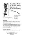
KIT CONTENTS
1079 Adj Track Rod:
For Fr Adj Track Rod Part
Bushings (2)
7/16” ID Sleeve
Heim End
Heim Spacers (2)
7/16” Flat Washer (2)
7/16” Lock Nut
3/4” Jam Nut
For Front Brake Lines
Bracket (2)
Brake Line Clip (2)
3/8” Crush Washers (4)
1077 Rear Shackles:
For Rear Shackles
(If purchased with 4 1/2” & 6” kit)
Bushings (4)
Sleeves (2)
9/16” x 4” Bolt (2)
9/16” Lock Nut (2)
14mm x 110mm Bolt (2)
14mm Lock Nut (2)
9/16” Flat Washer (8)

B
D
E
F
G
H
I
J
K
L
M
N
A
C
E
I
M
N
O
O
P
ADD-A-LEAF AND SHACKLES SHOWN IN PICTURE FOR 4” KIT. OPTIONAL SPRING KIT PART #8047 IS AVAIL-
ABLE FOR THIS VEHICLE.
6” KIT INCLUDES NEW LIFTED REAR SPRINGS AND SHACKLES.
KIT CONTENTS

PHOTO 2
PHOTO 1
INSTALLATION INSTRUCTIONS
1. Secure and properly block the tires on the vehicle on a level concrete surface.
2. Jack up the vehicle and place the front of the vehicle on jack stands.
3. Remove the front wheels and tires.
4. Support the axle with a floor jack.
5. Remove the upper mount of the stock shock absorbers using a 15mm wrench. Remove the lower stock hardware
using a 13mm wrench. Retain the hardware for reuse.
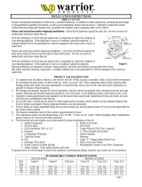
6. Remove the sway bar links on both sides using a T-55 torx bit /19mm wrench and a 15mm for the upper nut . See
Photo 1.
7. Remove the track bar from the axle housing on passenger side using a 15mm wrench. See Photo 2. Retain factory
bolt and flag nut for re-use.
8. Locate and remove the coil clip on the driver side lower coil spring seat using a 13mm wrench. Lower the axle to
allow for removal of the coil spring. Do not overextend the brake lines. Remove the caliper from the rotor to allow
the axle to lowered using a 13mm socket. Do not let the brake caliper hang from the brake line. Remove coil spring.
See Photo 3. Repeat for opposite side.
9. With the differential supported, remove the driver side lower control arm from the vehicle using a 21mm wrench. See
Photo 4. Retain factory hardware, as it will be reused. Repeat for opposite side.
10. Lower the axle using the floor jack.
PHOTO 3 PHOTO 4
Remove upper sway bar link from sway bar Remove the track bar from the axle.
Remove the coil clip from the coil spring Remove the lower control arm

11. Using a reciprocating saw, cut the stock lower control arm mounts even with the frame. See Photo 5.
12. After cutting , grind the edges down smooth. See Photo 6.
13. Remove the upper control arms from the axle as shown in Photo 7 and the frame location using a 15mm Socket /
wrench. Retain axle hardware
14. Support the transmission with a transmission jack or comparable jack.
15. Remove the 4 transmission nuts from the cross member using a 1/2” socket. See Photo 8. Retain the hardware for
reuse.
16. While the transmission is supported with a floor jack, remove the transmission cross member as shown in Photo 9
using a 15mm socket. It will also be necessary to remove the factory studs that secure the cross member to the
frame if not previously removed. Note: The jam nut method can be used to remove the studs or a stud extractor.
17. Position the new cross member on the frame rail aligning the two factory holes for the cross-member as shown in
Photo 10 with the supplied 10mm x 35mm bolts in the center hole of the new bracket. Snug but do not fully tighten
the bolts using a 17mm wrench.
PHOTO 5 PHOTO 6
CUT HERE
PHOTO 7 PHOTO 8
PHOTO 9 PHOTO 10
Remove the lower mount from the Jeep Grind the surface smooth
Remove the upper control arms Remove the mounting hardware
Remove the cross-member hardware Install the new cross-member

18. Install the side plates with the supplied 10mm x 35mm bolts as shown. Snug but do not fully tighten at this time See
Photo 11.
19. Center punch and drill using a 17/32 drill bit. See Photo 12.
20. Remove the side plates and drill the rear hole only using a 25/32” drill bit. See Photo 13.
21. Install the crush sleeves in the frame. See Photo 14.
22. Reinstall the side plates with the supplied 1/2” x 4 1/2” bolts and nuts in the rear holes using a 3/4” wrench. See
Photo 15.
23. Secure using the supplied 1/2” x 1 1/2” bolt and flag nut in the front holes of the side plates. See Photo 16. Tighten
using a 3/4” socket.
PHOTO 11 PHOTO 12
PHOTO 13 PHOTO 14
PHOTO 15 PHOTO 16
Rear
Rear
Install the side plates Drill using a 17/32” drill bit
Drill rear hole only using a 25/32” drill bit Insert crush sleeve in frame rail
Secure with supplied hardware Place flag nut in frame

24. Secure the transmission mount to the new cross member with the stock hardware. Tighten using a 1/2” wrench.
25. Adjust the lower arm to a measurement of 29 3/4” (26 1/4” on 2.8L motor) from eye to eye and install the arm in the
new cross member with the supplied 9/16” x 4” bolts. Do not tighten at this time. See Photo 17.
26. Install the new lower arm on the axle with the stock hardware. Do not tighten the lower control arm at this time.
27. Locate the new adj upper control arm and adjust the arm to a measurement of 15 1/4” from eye to eye.
28. Install the new upper arm on the new lower control arm with the supplied 10mm x 80mm hardware. Do not tighten at
this time.
29. Install the bent driver upper control arm on the axle with the supplied 10mm x 80mm bolts, washers and lock
nuts. Do not tighten at this time. See Photo 18. Install the straight upper control arm on the passenger side.
30. Position the new skid plate in place on the new cross member and install using the supplied 3/8” x 1” bolts, lock
washers and flat washers. Tighten using a 9/16” Socket / Wrench. See Photo 19.
31. Using the bracket as a guide, drill the frame rail using a 23/64” drill bit. See Photo 20.
32. Install the supplied 3/8’” X 1” self tapping bolts. Tighten to 30 ft/lbs using a 9/16” Socket. See Photo 21.
33. Remove the track rod from the axle using a 15mm wrench /socket.
34. Remove the cotter pin from the track rod end on the frame and remove the nut using a xx socket (frame).
35. Remove the stock track rod bracket from the drivers side of the vehicle by removing the two side nuts on the frame
using a 18mm socket and the two lower bolts shown in Photo 22 on the bottom of the frame rail using a 15mm
wrench / socket. Retain the stock hardware for reuse.
PHOTO 17 PHOTO 18
PHOTO 19 PHOTO 20
PHOTO 21 PHOTO 22
Install lower control arm bolts Install upper control arm
Insert the supplied hardware Drill the frame using a 23/64” drill bit
Insert the supplied 3/8” x 1” hardware Remove the track rod bracket

36. Place the new track rod bracket in place on the studs on the side of the frame rail and tighten using a 18mm socket.
See Photo 23.
37. Secure the bracket on the frame rail with the stock bolts on the bottom as shown in Photo 24. Tighten using a
15mm wrench / socket.
38. Lubricate the bushings with a lithium grease and assemble them in the track rod body end with the supplied 7/16’
sleeve.
39. Install the track rod on the frame bracket with the supplied 7/16” x 2 3/4” bolt, washers & nut. See Photo 25. Do not
tighten at this time.
40. Make sure the body is centered over the axle and install the passenger side of the track rod on the axle with the sup-
plied heim spacers, 7/16” x 2 3/4” bolt, washers & nut. If axle is centered, remove from the axle and tighten jam nut
to track rod body using 1 1/8” wrench. See Photo 26.
41. Tighten the axle and frame end using a 15mm wrench / socket as shown.
42. Remove the cotter pin and nut from the drag link at the pitman arm. Retain the nut to be reused. Separate the drag
link ball stud from the pitman arm with a puller tool. Do not use a pickle fork.
43. Mark the position of the original pitman arm. Remove the nut and washer from the steering gear box. Align and in-
stall new pitman arm on the steering gear shaft. Install the washer and nut. Tighten to 185 ft. lbs
44. Proceed to sway bar and brake line install on next page.
PHOTO 23 PHOTO 24
PHOTO 25
Install the track rod bracket Install the stock hardware
Install the supplied hardware in track rod Install 7/16” X 2 3/4” Bolt, washer & nut
PHOTO 26

45.Install the upper sway bar mount on the top of front sway bar where the stock link was secured, using the supplied
3/8” x 1.25” bolt lock washer and flat washer. Tighten using a 9/16” wrench making sure the mount is straight. See
Photo 27.
46. Using a hammer, remove the lower stock sway bar link mounting bolt from the axle mount.
47. Install supplied pin on the axle. See Photo 28. Hold using a screwdriver & tighten 1/2” lock nut using a 3/4” wrench.
48.Assemble the sway bar link with the link body, the jam nut and rod end Adjust the sway bar to a length of 11 1/4”
from top to bottom. Tighten the jam nut against the rod end using a 5/8” & 3/4” wrench.
49.Install the sway bar link on the upper sway bar mount with the supplied 1/2” flange lock nut. See Photo 29. Tighten
using a 5/8” & 3/4” wrench.
50.With the sway bar link installed on the supplied frame bracket, swing the bracket and sway bar link up and position
the bracket on the frame as shown in Photo 30.
51. While holding the bracket in place, remove the sway bar link from the bracket. Mark and drill the holes using a 1/4”
drill bit.
52. Install the supplied 5/16” x 1” self tapping bolt in the drilled holes and tighten using a 1/2” socket. See Photo 31. Do
not over tighten the self tapping bolts.
53. Install on the lower axle mounting pin. Install the disconnect pin. See Photo 32. Note: When disconnected the
hitch pin will be used on the upper mount to secure the sway bar link to the mount.
PHOTO 28
PHOTO 29
PHOTO 29
PHOTO 32
Install the sway bar link on the axle with hitch pin
PHOTO 30
PHOTO 31
Install the pin on the axle
Install the link on the mount Place the mount on the uni-body
Install the 5/16” x 1” self tapping bolts
PHOTO 27
Install Bracket using Thick Washer

54. Remove the front brake line from the frame rail hard line as shown in Photo 33 and remove the brake line from the
frame using a T-30 socket. Retain the factory hardware.
55. Remove the brake line from the caliper using a 15mm wrench.
56. Install the new brake line bracket on the frame with the factory hardware using a T30 Torque Bit. Install the brake
line in the bracket and attach to the hard line. See Photo 34. Secure with supplied brake line clip.
57. Install the brake line on the caliper using a 14mm socket and install the caliper on the axle. Tighten using a 13mm
socket.
58. Install the coil springs and reinstall the factory coil spring clips as removed using a 13mm wrench.
59. Install the tires and wheels.
60. Jack up the vehicle and remove the jack stands. Lower the vehicle to the ground.
61. Tighten the upper and lower control arms using a 15mm & 21mm wrench.
62. Proceed to the rear of the vehicle.
PHOTO 33 PHOTO 34
Remove line from the uni-body Install the new line with bracket

REAR INSTALLATION
This section will be used as reference when the add a leaf and shackle are installed. If leaf springs are used pro-
ceed to the next section.
1. Remove rear factory shocks using a 13mm wrench on top and a 3/4” wrench on bottom and retain hardware.
2. Chock the front wheels and jack up the rear of the vehicle and place the vehicle on jack stands. Remove the wheels
and tires.
3. Working from the drivers side, remove the factory u-bolts and lower the axle with a floor jack. Repeat for passenger
side.
4. To install the add-a-leafs if purchased with the kit; separate the springs and install the provided add-a-leaf in the
spring pack using a pyramid pattern smallest on the bottom graduating to largest on top. The factory flat overload
leaf should remain on the bottom of the pack (if equipped).
5. Clamp the spring with the c-clamp and tighten with the supplied center bolt with the nut on top of the spring and to
not leave a gap between the springs. Cut the thread of the bolt smooth with the nut.
6. Realign the center pin in the leaf spring pack to the centering hole on the axle perch.
7. Install new bend clips on spring.
8. Remove the stock shackle from the frame mount using a 21mm wrench. See Photo 1. Locate and either grind or cut
off the excess from the bolt pictured in Photo 2. This will allow the shackle to move rearward.
9. Install the new Rough Country lifted shackle and secure with supplied 9/16” x 4” hardware in the top hole and the
14mm x 110mm in the bottom hole. Do not fully tighten the hardware at this time. See Photo 3.
10. This kit includes 2 3/4” & 3” diameter u-bolts for rear axle options on the Jeep. Confirm axle diameter and use appro-
priate u-bolt. Install the u-bolts and torque to factory specs using 3/4” wrench.
11. Trial fit the new shocks with factory hardware on the axle and make note where to grind the stock mount to allow the
shock to be installed. After the area is marked, remove the shock and grind the area. See Photo 4. Reinstall the
shock and check to make sure the shock is not contacting the stock mount. If it is repeat the procedure. If not tighten
the shock bolt and washer. Do not over tighten the lower shock mount. When tightening the bushing should
swell slightly. Torque the upper using a 13mm wrench and lower bolts using 3/4” wrench to factory specs. Repeat
for other side.
12. Install the tires and wheels. Jack up the vehicle and remove the jack stands. Lower the vehicle to the floor.
13. Torque the frame bolts, and shackle bolts to factory specs using a 21mm wrench.
PHOTO 1
PHOTO 3
PHOTO 2
Remove the spring from the shackle Grind the bolt pictured as needed
Install the shackle with stock hardware
PHOTO 4
Grind the factory shock mounts

POST INSTALLATION INSTRUCTIONS
1. Check all fasteners for proper torque.
2. Check to ensure there is adequate clearance between all rotating, mobile, fixed and heated members.
3. Check steering gear for interference and proper working order.
4. Before driving the vehicle, check to make sure brakes are operating properly and do not need to be bled.
5. Perform steering sweep.
6. Check to ensure brake hoses have sufficient slack and will not contact rotating, mobile, or fixed members. Adjust
lines/brackets to eliminate interference and maintain proper working order. Failure to perform inspections may result
in component failure.
7. Have headlight readjusted to proper settings.
8. Take the vehicle to be aligned to factory specifications by a certified alignment shop.
9. Re torque all fasteners after 500 miles. Visually inspect components and re torque fasteners during routine vehicle
service.
Thank you for choosing Rough Country for your suspension needs.
LEAF SPRING INSTALLATION
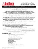
1. Remove the stock brake line clip on the driver side
where the rubber line meets the steel line.
2. Remove the rubber line from the steel hard line and re-
move from the axle using a 15mm & 10mm wrench on
the frame rail and a 14mm & 10mm wrench on the axle.
3. Install the new braided line on the hard line as the stock
was removed and install the supplied brake clip. See
Photo 1.
REAR BRAKE LINE INSTALLATION
OPTIONAL SPRING KIT FOR 4” KIT AND 6” KIT
1. Support the axle with jack stands.
2. Remove the tires/wheels
3. Remove rear factory shocks using a 13mm wrench on top and a 3/4” wrench on bottom and retain hardware
4. Remove the u-bolts from the axle using a 3/4” socket.
5. Remove the springs from the frame and shackle using a 21mm socket /wrench and remove the springs from the ve-
hicle. Retain the factory hardware.
6. Install the new springs with the factory hardware. Do not tighten at this time.
7. Install the supplied u-bolts and tighten using a 3/4’ socket.
8. Install the tires/wheels.
9. Jack up the vehicle and remove the jack stands.
10. Lower the vehicle to the ground and tighten the leaf springs using a 21mm socket / wrench.
PHOTO 1
Install the new line to the steel line
/