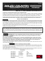
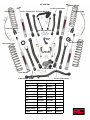
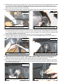
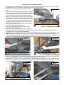
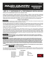
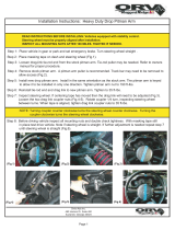
Rough Country 68322 is a 6” suspension system designed for Jeep JK 4 DR vehicles. It provides improved ground clearance, allowing for larger tires and better off-road performance. The kit includes front and rear coil springs, adjustable control arms, a track bar, sway bar links, and a pitman arm.
With this suspension system, you can expect enhanced handling and stability, both on and off-road. The adjustable control arms allow for fine-tuning of the suspension geometry, while the upgraded track bar and sway bar links improve handling and reduce body roll. The pitman arm ensures proper steering geometry after the suspension lift.
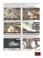
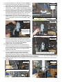
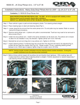


-
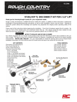
 1
1
-
 2
2
-
 3
3
-
 4
4
-
 5
5
-
 6
6
-
 7
7
-
 8
8
-
 9
9
-
 10
10
-
 11
11
-
 12
12


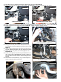
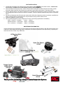
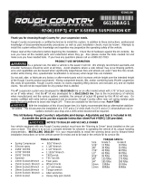
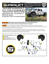
Rough Country 68322 is a 6” suspension system designed for Jeep JK 4 DR vehicles. It provides improved ground clearance, allowing for larger tires and better off-road performance. The kit includes front and rear coil springs, adjustable control arms, a track bar, sway bar links, and a pitman arm.
With this suspension system, you can expect enhanced handling and stability, both on and off-road. The adjustable control arms allow for fine-tuning of the suspension geometry, while the upgraded track bar and sway bar links improve handling and reduce body roll. The pitman arm ensures proper steering geometry after the suspension lift.
Ask a question and I''ll find the answer in the document
Finding information in a document is now easier with AI
Related papers
-
 Rough Country 68422 Installation guide
-
 Rough Country Front Sway Bar Quick Disconnects Installation guide
-
 Rough Country 89708 Installation guide
-
 Rough Country 67430 Installation guide
-
 Rough Country 66220 Installation guide
-
 Rough Country 4in Suspension Lift Kit Installation guide
-
 Rough Country 66130 Installation guide
-
 Rough Country 3.5in Suspension Lift Kit Installation guide
-
 Rough Country 69620 Installation guide
-
 Rough Country 4in Suspension Lift Kit Installation guide


Other documents
-
 Teraflex Front Swaybar Quick Disconnects Installation guide
-
Lynx Front & Rear Control Arm Kit Installation guide
-
 Rugged Ridge 18475.02 Installation guide
-
 Synergy Manufacturing 8059-11 Installation guide
-
 Warrior Products 30840 Installation guide
-
Skyjacker 2.5in Front Coil & 1in Rear Spacer Lift Installation guide
-
-
 Rugged Ridge 18006.50 Installation guide
-
 Rugged Ridge 18006.55 Installation guide
-
 Superlift 40051 Installation guide


