Page is loading ...

Not for
Reproduction
OPERATOR’S
MANUAL
FAST-Vac
Grass Collection Systems
61” Mower Decks
with Setup Instructions
IMPORTANT NOTE:
These FAST-Vac Systems fit
2005 and newer Model Year
product equipped with the rubber
discharge chute.
5103133
Rev E
System Number: Description: Fits Models: Serial Number Range:
5600005 3 Bag System - 61” Mower Deck IS3100ZL
5600006 3 Bag System - 61” Mower Deck IS3000Z
IS3000ZX
S/N: 3631 & Above
5600008 3 Bag System - 61” Mower Deck IS1000Z S/N: 2899 & Above
5600009 3 Bag System - 61” Mower Deck IS4500Z
5600057 3 Bag System - 61” Mower Deck IS2000Z
S200X
5600060 3 Bag System - 61” Mower Deck IS3100Z
5600083 3 Bag System - 61” Mower Deck IS3100ZBS

Not for
Reproduction
b www.ferrismowers.com | www.snapperpro.com
Briggs & Stratton Power Products Group, LLC.
Copyright © 2016 Briggs & Stratton Corporation
Milwaukee, WI, USA. All rights reserved.
FERRIS is a trademark of Briggs & Stratton
Corporation Milwaukee, WI, USA.
SNAPPER PRO is a trademark of Briggs & Stratton
Corporation Milwaukee, WI, USA.
General Information
Thank you for purchasing this quality-built Ferris or Snapper Pro product. We’re pleased that you’ve placed your
confidence in the Ferris or Snapper Pro brand. When operated and maintained according to the instructions in
this manual, your Ferris or Snapper Pro product will provide many years of dependable service.
This manual contains safety information to make you aware of the hazards and risks associated with this
machine and how to avoid them. This machine is designed and intended to be used and maintained according
to the manual for finish cutting of established lawns and is not intended for any other purpose. It is important that
you read and understand these instructions thoroughly before attempting to start or operate this equipment.
DATE PURCHASED / FECHA COMPRADA
Contact Information:
Briggs & Stratton Power Products Group, LLC.
5375 N. Main St.
Munnsville, NY 13409-4003
(800) 933-6175
www.ferrismowers.com
www.snapperpro.com

Not for
Reproduction
SAFETY RULES & INFORMATION .................... 2
Safety Decals ..........................................................3
Safety Icons ............................................................4
GENERAL OPERATING INSTRUCTIONS .......... 6
Before Operation .....................................................6
Mowing with the Double / Triple Catcher ................6
After Operation ........................................................6
Storing the Grass Catcher ......................................6
Mowing Without the Blower ....................................6
INSTALLATION ................................................... 7
Suspension Adjustment ..........................................7
Prepare Discharge Chute Opening .........................8
Preparing the Blower Mount for Assembly .............9
Prepare the Blower Assembly for
Installation (IS4500Z Models Only) .......................10
Blower Assembly ..................................................12
Mower Deck Preparation ......................................14
Blower Installation .................................................16
Collector Installation ..............................................18
Weight Mount Installation .....................................25
BLOWER & COLLECTOR REMOVAL ............. 29
MAINTENANCE .................................................30
Maintenance Schedule .........................................30
Check the Blower Housing and Impeller ..............30
Check the Conditioning of the Collection Bags ....30
Lubrication ............................................................30
Unplugging a Clogged Unit ...................................31
TROUBLESHOOTING........................................32
1
Table of Contents

Not for
Reproduction
2 www.ferrismowers.com | www.snapperpro.com
GENERAL WARNINGS
• Know the mower controls, safety rules and how
to stop quickly. READ AND UNDERSTAND THE
MOWER OPERATOR’S MANUAL.
• Read and obey all safety decals.
• Wear appropriate ear, eye and breathing
protection.
• Only allow responsible adults, who are familiar
with the instructions, to operate the unit.
• Disengage the electric clutch (PTO). Shut off the
engine and wait for all moving parts to stop before
attaching, adjusting, or disconnecting any part of
the collection system.
• Check the collection system to make sure it is
bolted tightly to the rider.
• DO NOT operate the mower without either the
entire grass catcher or the deflector in place.
• Turn off the PTO switch to disengage the blades
when not mowing.
• DO NOT mow in reverse. Always look down and
behind before and while travelling in reverse.
• DO NOT turn sharply when travelling alongside a
building or any object. Slow down before turning.
• DO NOT carry passengers on the rider.
• When blower assembly is removed from the
mower deck, the deflector must be properly
installed.
• Collector bags are subject to deterioration
and wear during normal use. Inspect the bag
periodically for tears, holes or weak spots and
replace with a new bag that meets manufacturer’s
durability standards.
• If the mower stalls or the turbo blower chute plugs:
1. Disengage the electric clutch (PTO);
2. Stop the engine and remove the key;
3. Set the parking brake, and wait for all moving
parts to stop.
4. Remove the foreign object or clear the chute
with a piece of wood before restarting the
engine. NEVER place hands into blower
housing to clear jammed object. Blower
may rotate when object is removed.
• For added rider stability and to prevent tipping or
loss of control:
a. Use reduced speed on uneven ground and
when turning corners.
b. Reduce loads on hillsides. It is recommended
that the collection system be kept no more
than half full when negotiating any slopes. Start
mowing on slopes when the collection system
is empty.
c. Mow across the face of slopes; not up and
down.
• Never operate on slopes greater than 17.6%
(10°).
Read these safety rules and follow them closely. Failure to obey these rules could result in loss
of control of unit, severe personal injury or death to you, or bystanders, or damage to property or
equipment. This mowing deck is capable of amputating hands and feet and throwing objects.
The triangle in text signifies important cautions or warnings which must be followed.
Safety Rules & Information

Not for
Reproduction
3
GB
Safety Rules & Information
Safety Decals
Before operating your unit, read the safety decals. The
cautions and warnings are for your safety. To avoid a
personal injury or damage to the unit, understand and
follow all the safety decals.
WARNING
If any safety decals become worn or damaged,
and cannot be read, order replacement decals
from your dealer.
Previous Units with Text Decals
A
B
C
D
A. Part Number: 3046850 - “Decal, Danger/
Warning”
B. Part Number: 3046851 - “Decal, Warning-
Blower”
C. Part Number: 3046883 - “Decal, Warning-
Shield”
D. Part Number: 7027733 - “Decal, Ear
Protection”
Current Units with Icon Decals
A
B
A. Part Number: 5104313 - “Decal, Blower,
Small, Icons”
B. Part Number: 5104314 - “Decal, Blower,
Main, Large, Icons”

Not for
Reproduction
4 www.ferrismowers.com | www.snapperpro.com
2-Bag & 3-Bag Collector Hood
A. Decal, Container, Icons (Sewn into fabric
of collector hood)
Safety Icons
Danger - Rollover hazard:
• Do not operate up or down slopes or without the
front counter balance weights.
• Operate on slopes only if under 10 degrees.
• Always use front counterbalance weights while
operating on slopes.
Warning - Amputation and thrown objects hazard:
• To avoid injury from rotating parts (of the blower).
• Stay clear of parts and keep all shields and guards
in place.
• Operate blower only with entire collection system
installed and latched closed.
Warning - Amputation and thrown objects hazard:
• Disengage the blower (blades) and remove
the ignition key, wait for all parts to stop before
disconnecting or unlatching any parts attached to
blower or collection system.
Warning - Read the Operator’s Manual.
Caution - Always wear hearing protection when
operating.
Warning - Loss of traction and control hazard:
• Do not operate with only the collection system
installed.
• Do not operate with only the front counter balance
weights installed.
• Operate only with both the entire collection system
and front counter balance weights installed and the
collection system closed and latched.
Danger - Dismemberment:
• This machine can crush and cut. Keep hands
away from belts and pulleys.
Danger - Amputation and thrown objects hazard:
• To avoid injury from rotating blades, stay clear of
deck edge and keep others away.
A
Safety Rules & Information

Not for
Reproduction
5
Danger - Thrown objects hazard:
• Do not mow without discharge chute or entire grass
catcher in place.
Warning - Thrown objects hazard:
• Do not open collection system container with
engine running.
• Do not operate with blower or collection system
tube unlatched or missing.
• Operate only with both the entire collection system
and front counterbalance weights installed and the
collection system closed and latched.
Warning - Loss of traction and control hazard:
• Do not operate with only the collection system
installed.
• Do not operate with only the front counter balance
weights installed.
• Operate only with both the entire collection system
and front counter balance weights installed and the
collection system closed and latched.
Safety Rules & Information

Not for
Reproduction
6 www.ferrismowers.com | www.snapperpro.com
WARNING
ALWAYS shut off the tractor. disengage
the PTO, and allow all moving parts to stop
BEFORE disconnecting or clearing tube, or
emptying catcher.
Before leaving the operator’s position for any
reason, engage the parking brake, disengage
the PTO, stop the engine and remove the key.
To reduce fire hazard, keep the engine, rider
and mower free of grass, leaves and excess
grease. Do not stop or park rider over dry
leaves, grass or combustible materials.
CAUTION
This machine produces sound levels
in excess of 85 dBA at the operator’s
ear and can cause hearing loss though
extended periods of exposure.
Wear hearing protection when operating this
machine.
General Operating Instructions
BEFORE OPERATION
Clear the lawn of all sticks, stones, wire and other
debris which may be caught or thrown by the mower
blades.
Check grass condition. If wet, wait until later in the
day. If grass is wet, the grass catcher is likely to
become plugged.
For efficient bagging, air circulation under the
mower deck, through the chute and into the bag is
very important.
For this reason, BEFORE YOU BEING MOWING you
should make certain this underside of the mower and
the underside of the catcher lid are free from grass
and debris.
Make sure that there is a snug fit between mower
deck, blower housing, tubes and grass catcher covers.
MOWING WITH THE DOUBLE /
TRIPLE CATCHER
Always operate with throttle at full speed when
mowing.
Always wear hearing protection when operating
grass catcher.
Grass should be cut often, and not too short. If grass
is too long or lush it may be necessary to keep ground
speed to a minimum or to cut only half the width of the
mower to prevent clogging. If grass is long, operate
with mower in high cutting position for first pass,
cutting again in a lower position on a second pass.
Do not open the cover with mower engaged.
If a large amount of cut grass is spilling out from
under deck, the tube may be plugged or the bags
may be full— discontinue mowing, stop the rider,
disengage the PTO and then empty the catcher or
clear the tube.
AFTER OPERATION
Remove any debris from the screen on the underside
of the lid. Note: The lid screen can be partially
removed for easier cleaning and should be cleaned
regularly.
The blower housing and tube should be removed for
cleaning.
Inspect the grass bags for wear or damage. Make
sure that there is a snug fit between mower deck,
blower housing, tubes, and grass catcher cover.
STORING THE GRASS CATCHER
Clean the grass catcher thoroughly using a mild
detergent (other products may damage the tube).
Remove any debris from the the screen on the
underside of the lid. The screen can be partially
removed for easier cleaning.
If paint has been scratched on metal parts, touch
up with paint, or apply a thin film of oil to prevent
corrosion.
Store in a dry area. Hang the catcher and catcher
bags to dry thoroughly before storing for a long period
of time. Always store away from moisture.
MOWING WITH THE BLOWER
For operation without the blower, the deflector must
be properly installed in the down position.
To remove the blower, reverse the installation steps.

Not for
Reproduction
7
GB
REAR SUSPENSION ADJUSTMENT
For IS1500ZX & IS2000Z Models:
The upper mounting position # 2 (See Figure 1)
should be used when a rear-mount grass bagger
system is installed.
To adjust the upper mounting position:
1. Park the machine on a flat, level surface.
Disengage the PTO, stop the engine and engage
the parking brake.
2. Raise the rear of the machine and secure with
jackstands. The jackstands must be under the
bumper. Chock the front wheels to prevent the
machine from rolling.
3. Position the jack under the cross member that ties
the suspension arms together and slowly raise
the rear suspension to relieve the pressure on the
upper mounting bolts.
NOTE: This will require small adjustments to the
jack’s position. The shock should move freely on the
mounting bolt when the pressure is relieved.
4. Remove the upper shock mounting hardware and
pivot the shock to position # 2 (see Figure 1).
Adjust the jack to align the shock mounts to the
shocks.
5. Reinstall the upper shock mounting hardware and
tighten securely.
6. Remove the jack from under the suspension cross
member.
7. Remove the jackstands from under the machine.
For All Models:
More spring pre-load should be used with heavy
weight operators.
4. See Figure 1. Using the supplied spanner wrench
(p/n 5022853), insert the tip of the wrench into
the notch of the pre-load adjuster. While holding
the wrench in place with one hand, turn counter-
clockwise to increase the pre-load turn clockwise
to decrease the pre-load. Make sure both shocks
are sent to the same amount of pre-load.
5. Reinstall the rear drive tires. Torque the lug
bolts to 85-95 ft. lbs. (115-129 Nm). Remove the
jackstands from under the machine.
NOTE: Spanner wrench is located under the seat on
the right-hand side of the machine or near the parking
brake switches.
Figure 1. Rear Suspension Adjustments
POSITION #1
(FACTORY SET)
POSITION #2
(GRASS BAGGER)
WARNING
Use two hands when adjusting the shock
springs. This will prevent the wrench from
slipping while pressure is being applied.
To adjust the spring pre-load:
1. Park machine on a flat, level surface. Disengage
the PTO, stop the engine and engage the parking
brake.
2. Raise the rear of the machine and secure with
jackstands. Chock the front wheels to prevent the
machine from rolling.
3. Remove the rear drive tires.
Installation

Not for
Reproduction
8 www.ferrismowers.com | www.snapperpro.com
Installation
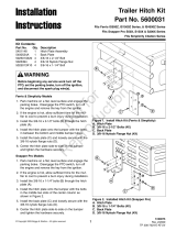
PREPARE DISCHARGE CHUTE
OPENING
Remove the Discharge Chute & Deck
Guard
1. Remove the discharge chute (A, Figure 2), chute
mount rod (B) and mounting hardware.
NOTE: Retain the discharge chute, chute mount rod,
and mounting hardware. If the blower is removed
from the unit they need to be reinstalled for safe
operation.
2. Remove the chute lock bolt (C) and nut.
3. Remove the deck guard (D). Save the bolts and
washers, as they will be required in a later step.
Remove the Deflector Plate
1. Loosen and remove the hardware (E, Figure 2)
that secures the deflector plate (F) to the mower
deck (G).
2. Remove the deflector plate.
3. Save the plate and hardware. When operating the
unit without the collection system installed, the
user will experience a better cutting quality if the
deflector plate in reinstalled.
A
B
C
D
F
E
H
G
Figure 2. Remove Chute & Guard
A. Discharge Chute
B. Chute Mount Rod
C. Chute Lock Bolt
D. Guard
E. Deflector Plate Mount Hardware
F. Deflector Plate
G. Mower Deck
H. Discharge Chute Rod Mount Hardware
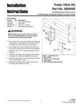
1-1/2"
(3,8 cm)
5/8"
(1,6 cm)
3/8" Drill
Figure 3. Discharge Chute Mount
Drill Hole in Discharge Chute Bracket
1. Examine the discharge chute mount bracket on
the mower deck (see Figure 3). If the hole pattern
looks like the one shown, you must drill a 3/8”
hole in the location specified in Figure 3.

Not for
Reproduction
9
Installation
PREPARING THE BLOWER MOUNT
FOR ASSEMBLY
Inspecting the Blower Mount Assembly
Some blower mounts are equipped with an adjustable
deflector bracket (A, Figure 4). If your blower mount
is equipped with an adjustable deflector bracket it will
need to be adjusted prior to performing the Blower
Assembly procedure. If not, proceed with the Blower
Assembly procedure.
Adjusting the Blower Mount Assembly
Adjustable Baffle
1. Temporarily install the blower mount (A, Figure 5)
onto the mower deck (B). Refer to Figure 5 for the
position of the pins w/ lanyards in relationship to
the chute mount bracket on the mower deck. The
pins w/ lanyards fit into the same holes that the
chute mount rod was installed.
2. Loosen the two (2) 5/16” nylock flange nuts (A,
Figure 6) and the two (2) 1/4” nylock flange nuts
(B) that secure the deflector bracket (C) to the
blower mount (D).
3. Slide the deflector bracket up against the front
baffle (E) of the mower deck (F).
4. Tighten two (2) 5/16” nylock flange nuts and the
two (2) 1/4” nylock flange nuts.
5. Remove the blower mount and pins w/ lanyards
from the mower deck.
Figure 5. Install Blower On Deck (Notice Pin
Orientation)
A. Blower Mount
B. Mower Deck
A
Figure 4. Inspecting the Blower Mount Assembly
A. Adjustable Deflector Bracket
B
A
Figure 6. Adjusting the Deflector Bracket
A. 5/16” Nylock Flange Nuts
B. 1/4” Nylock Flange Nuts
C. Deflector Bracket
D. Blower Mount
E. Front Baffle
F. Mower Deck
A
B
D
E
F
C

Not for
Reproduction
10 www.ferrismowers.com | www.snapperpro.com
Installation
PREPARE THE BLOWER
ASSEMBLY FOR INSTALLATION
(IS4500Z MODELS ONLY)
1. Loosen the 3/8-24 hex nut (A, Figure 7) that
secures the idler arm (C) to the blower assembly.
Remove the idler arm assembly from the blower
assembly.
2. Loosen the 1/2” hardware that secures the idler
pulley (G) to the idler arm assembly. Remove the
idler pulley from the idler arm assembly. Discard
both spacer and bolt that secured the idler pulley
to the idler arm assembly.
3. Refer to Figure 1. Install the new 1/2-13 X 2-1/4”
bolt (J) through the belt keep (I), which should be
positioned with the tab facing up, then through
the idler arm (C) which should be positioned with
the hub facing up, then through the idler pulley
(G) and then through the 1/2” washer (H). Next
loosely secure with the 1/2-13 hex nylon lock nut
(F). It will be necessary to reposition the belt keep
later.
4. Set the idler arm assembly aside for reinstallation
later.
5. Loosen the 3/8-16 hex serrated flange nut (A,
Figure 8) that secures the fixed idler pulley, and
belt keep (B) to the blower assembly.
6. Remove the 3/8-16 hex serrated flange nut (A)
and the belt keep (B) from the 3/8-16 X 2” bolt (F).
Discard the idler pulley.
7. Reassemble the stationary idler pulley
components as shown in Figure 8. Install the
3/8-16 X 2” bolt (F) with washer (E), through the
steel idler pulley (D), which should be positioned
with the hub facing up, then through the blower
assembly. Install the .14 X 1.75 X .14 washer
(C) above the blower assembly onto the bolt (F),
through the belt keep (B) with the tab facing down
and secure with a 3/8-16 hex serrated flange nut
(A).
Figure 7. Updating the Idler Arm Assembly
A. 3/8-24 Hex Nut
B. 3/8 Lock Washer
C. Idler Arm
D. 9/16 Narrow Flat Washer
E. Idler Stud
F. 1/2-13 Hex Nylon Lock Nut
G. Idler Pulley
H. 1/2 Washer
I. Belt Keep
J. 1/2-13 x 2-1/4” Bolt
A
B
D
C
D
E
F
H
I
J
G
Figure 8. Installing the New Washer
A. 3/8-16 Hex Serrated Flange Nut
B. Belt Keep
C. .41 X 1.75 X .14 Washer
D. Steel Idler Pulley
E. 3/8” SAE Washer
F. 3/8-16 X 2” Bolt
F
E
D
C
B
A

Not for
Reproduction
11
GB
8. Loosen the 3/8-16 hex serrated flange nut
(A, Figure 9) that secures the adjustable idler
pulley (D) to the blower assembly. Remove the
3/8-16 hex serrated flange nut (A), and all the
components the nut secured. Discard the 3/8-16 X
2” bolt and idler pulley.
9. Place the support plate (B) on the blower
assembly. Line up the two rows of holes in the
support plate with the two rows of holes on the
blower assembly.
10. Refer to figure 9. Place a 3/8-16 X 3/4 Bolt (C)
up through the blower assembly in the front most
hole of the inner row, through the support plate
(B) and secure with a 3/8-16 hex serrated flange
nut (A).
11. Reassemble the adjustable idler pulley
components as shown in Figure 9. Install the 3/8-
16 X 2-1/2” bolt (H) up through the belt keep (G)
which should be positioned with the tab facing up,
through the .39 X .75 X .38 spacer (F), through
the 3/8 SAE washer (E), through the steel idler
pulley (D), which should be positioned with the
hub facing up, then through the blower assembly,
then through the support plate (B) and secure with
a 3/8-16 hex serrated flange nut (A).
12. Using a 3/8” drill bit, drill a 3/8” hole through the
blower assembly using the left rear hole (see
Figure 9) as a guide.
13. Install a 3/8-16 X 3/4 bolt (C) up through the
blower assembly in the newly drilled hole, through
the support plate (B) and secure with a 3/8-16 hex
serrated flange nut (A).
14. Loosen the 3/8-16 X 2-1/2” bolt (H) enough so
that the belt keep (G) can be moved freely. It will
be necessary to reposition the belt keep later.
15. Reinstall the idler arm assembly to the blower
assembly as shown in Figure 10. Install the idler
stud (A, Figure 10) down through a 9/16 narrow
flat washer (B) then down through the idler arm
assembly (C), then down through another 9/16
narrow flat washer (B), then down through the
blower assembly, then down through the 3/8 lock
washer (D), and secure with the 3/8-24 hex nut
(E).
Installation
Figure 9. Installing the New Support Plate
A. 3/8-16 Hex Serrated Flange Nut
B. Support Plate
C. 3/8-16 X 3/4 Bolt
D. Steel Idler Pulley
E. 3/8” SAE Washer
F. .39 X .75 X .38 Spacer
G. Belt Keep
H. 3/8-16 x 2-1/2” Bolt
A
B
C
D
E
G
H
F
Outer
Row
Inner
Row
Drill
Here
D
E
B
C
B
A
Figure 10. Updating the Idler Arm Assembly
A. Idler Stud
B. 9/16 Narrow Flat Washer
C. Idler Arm Assembly
D. 3/8 Lock Washer
E. 3/8-24 Hex Nut

Not for
Reproduction
12 www.ferrismowers.com | www.snapperpro.com
Installation
BLOWER ASSEMBLY
1. Remove the existing 5/16-18 x 5/8” flange head
bolts (B, Figure 11) from the blower housing (A).
2. Install the blower mount plate (C) onto the blower
housing and reinstall the 5/16-18 x 5/8” flange
head bolts. Tighten securely.
3. Install three (3) 3/8-16 x 1” bolts and nylon lock
nuts (D) through the blower mount plate and
blower. The bolt heads must be installed on the
inside of the blower housing.
Figure 11. Install Blower Mount Plate
A. Blower Housing
B. 5/16-18 x 5/8” Bolts (existing)
C. Blower Mount Plate
D. 3/8-16 x 1” Bolts & Nylon Lock Nuts (3X)
B
D
C
B
A
4. Loop the idler spring (A, Figure 12) through the
1/4” x 2” eyebolt (B). Install the eyebolt through
the L-bracket on the blower mount and install the
1/4-20 nylock flange nut (C). Tighten the nut until
the eyebolt contacts the L-bracket.
C
A
B
Figure 12. Install Idler Spring
A. Idler Spring
B. 1/4” x 2” Eyebolt
C. 1/4-20 Nylock Flange Nut
D. Spring Anchor Bolt
E. Idler Arm
E
D

Not for
Reproduction
13
GB
5. Remove the blower belt guard and set aside.
IS1000Z, IS2000Z, IS3000Z, IS3100Z, S200X Series
Models:
6. Install the impeller drive pulley (A, Figure 13) onto
the impeller shaft (B) as described in Figure 13.
Install the 1/4” x 1-1/2” long key (not shown) in the
pulley.
7. Align the pulley groove with the appropriate slot
as described in Figure 13. Tighten the set screws
in the pulley.
8. Reposition the 3/8-16 x 6” bolt if required to line
up with the pulley groove.
IS4500Z Models:
9. Loosely install the tapered hub (A, Figure 14) into
the blower pulley (D). Install the blower pulley onto
the impeller shaft (E) and slide the blower pulley
in towards the blower assembly.
10. Position the new blower drive belt in the blower
drive pulley (D).
11. Position the blower pulley (D) so it is center with
the belt keeper bolt (F). Install the 1/4” X 1-1/2”
long key (C) into the blower pulley (D).
12. Install the two (2) 1/4-20 X 1” bolts (B) into the
tapered hub (A) and tighten evenly. Torque the
1/4” bolts to 8 ft. lbs. (10,9 Nm).
All Models:
13. Check the position of the idler pulley (A, Figure
15). The position must be aligned with the
position of the pulley (outer row of holes for pulley
hub pointing in, inner row of holes for pulley hub
pointing out). Reposition if necessary.
Inner Slot
Align pulley groove
with slot (outer slot
with pulley hub in
OR inner slot with
pulley hub out)
Figure 13. Install Impeller Drive Pulley
Inner Row
Outer Row
Figure 15. Check Idler Pulley Position
A. Idler Pulley
A
Hub pointing OUT:
All other 61” Models
Hub pointing IN:
61” IS3000ZL Model
61” IS3100Z Models
Installation
Outer Slot
Figure 14. Install Impeller Drive Pulley (IS4500Z
Models Only)
A. Tapered Hub
B. 1/4-20 X 1” Bolt
C. 1/4 X 1-1/2” Long Key
D. Blower Pulley
E. Impeller Shaft
F. Belt Keeper Bolt
A
B
C
D
E
F
61” IS3100ZL
Model
61” IS3100Z
Models
All other
61” Models

Not for
Reproduction
14 www.ferrismowers.com | www.snapperpro.com
A
B
Figure 16. Mower PTO Belt
A. Idler Arm
B. Stationary Idler Pulley
1000Z Series (61” Model), IS2000Z Series (61”
Model), IS3000Z Series & IS3100Z Series:
1. Using a 1/2” breaker bar, place the square end in
the square hole located in the end of the idler arm
(A, Figures 16). Carefully rotate the breaker bar
counter-clockwise, which will relieve the tension
on the belt exerted from the idler arm.
2. Slide the drive belt over the edge of the stationary
idler pulley (B). Carefully release the tension on
the breaker bar. Remove the belt from the right-
hand (discharge side) spindle pulley.
WARNING
IS2000Z, IS3000Z, IS3100Z, IS4500Z & S200X
Models:
Use extreme caution when rotating the idler
arm with the breaker bar, due to the increased
tension in the spring as the idler arm is being
rotated. Injury may result if the breaker bar is
prematurely released while the spring is under
tension.
Installation
IS4500Z Series:
1. Using a 1/2” breaker bar, place the square end in
the square hole located near the end of the idler
arm (A, Figures 18). Carefully rotate the breaker
bar clockwise, which will relieve the tension on the
belt exerted from the idler arm.
2. Remove the belt from the trim side spindle pulley
(B).
3. Carefully release the tension on the breaker bar.
4. Remove the belt from the right-hand (discharge
side) spindle pulley.
Figure 18. Spindle Drive Belt Removal
A. Idler Arm
B. Trim Side Spindle Pulley
B
A
A
B
B
Figure 17. Mower PTO Belt
A. Idler Arm
B. Stationary Idler Pulley
S200X Series:
1. Using a 1/2” breaker bar, place the square end in
the square hole located in the end of the idler arm
(A, Figures 17). Carefully rotate the breaker bar
counter-clockwise, which will relieve the tension
on the belt exerted from the idler arm.
2. Slide the drive belt over the edge of the stationary
idler pulley (B). Carefully release the tension on
the breaker bar. Remove the belt from the right-
hand (discharge side) spindle pulley.
MOWER DECK PREPARATION
Removing the Mower Belt
Identify and follow the correct procedure for your unit.

Not for
Reproduction
15
GB
Installation
Remove the Spindle Pulley
Identify and follow the correct procedure for your unit.
IS1000Z Series, IS2000Z, IS3000ZF & ZX Series &
S200X Series:
1. Remove the 3/4-16 hex nut & 3/4” spring washer
(A & B, Figure 19) securing the spindle pulley (C)
to the spindle shaft. Use a 1” wrench on the flats
of the blade end of the spindle shaft to prevent the
shaft from spinning. Save the 1/4” key (D).
IS3000ZL Series, IS3100Z Series, & IS4500Z
Series:
1. Measure and record the distance between the
bottom of the spindle pulley and the top of the
mower deck. This will be required when installing
the new pulley.
2. Remove the 1/4-20 x 1” bolts (E) securing the
tapered hub (F) to the spindle pulley (G) and
shaft.
3. Reinstall the bolts in the tapped holes of the
tapered hub and tighten evenly to remove the
hub from the pulley and shaft. Use a 1” wrench
on the flats of the blade end of the spindle shaft
to prevent the shaft from spinning. Save the 1/4”
key (D).
Figure 19. Remove Spindle Pulley
A. 3/4-16 Hex Nut
B. 3/4” Spring Washer
C. Spindle Pulley
D. 1/4” Key
E. 1/4-20 x 1” Bolts
F. Tapered Hub
G. Spindle Pulley (tapered bore)
Install the Double Spindle Pulley
Identify and follow the correct procedure for your unit.
IS1000Z Series, IS2000Z, IS3000ZF & ZX Series &
S200X Series:
1. Install the double spindle pulley (C, Figure 20) and
1/4” key (D) onto the spindle shaft.
2. Install the 3/4” spring washer (B) with the cone
facing up (see insert, Figure 20). Install the 3/4-
16 hex nut (A) and torque to 85-90 ft. lbs (115-122
Nm). Use a 1” wrench on the flats of the blade
end of the spindle shaft to prevent the shaft from
spinning.
IS3000ZL Series, IS3100Z Series, & IS4500Z
Series:
1. Remove the 1/4-20 x 1” bolts (E) from the tapered
hub (F). Install the bolts through the clearance
holes in the hub and into the new double spindle
pulley (G).
2. Install the pulley, hub and 1/4” key (D) onto the
spindle shaft.
3. Hold the pulley at the height measure previously
and tighten the 1/4” bolts evenly. Torque the 1/4”
bolts to 8 ft. lbs. (10.9 Nm). Use a 1” wrench on
the flats of the blade end of the spindle shaft to
prevent the shaft from spinning.
Figure 20. Install Double Spindle Pulley
A. 3/4-16 Hex Nut
B. 3/4” Spring Washer
C. Double Spindle Pulley
D. 1/4” Key
E. 1/4-20 x 1” Bolts
F. Tapered Hub
G. Double Spindle Pulley (tapered bore)
A
D
C
G
F
E
D
A
B
C
D
E
F
G
D
B

Not for
Reproduction
16 www.ferrismowers.com | www.snapperpro.com
Installation
Reinstall the Spindle Belt
Refer to the belt removal instructions on Page 12
and reverse the order for reinstalling the belt.
Install the Deck Guard
1. Install the new deck guard onto the mower deck
and secure with the hardware previously removed
(see Figure 21).
NOTE: The IS4500Z Series has a 3-piece deck
guard. Install as shown in Figure 22.
Figure 21. Install Guard
Figure 22. Install Guard - IS4500Z Series
BLOWER INSTALLATION
Install the Blower
1. Install the blower onto the mower deck. Refer
to Figure 23 for the position of the quick pins in
relationship to the chute mount bracket on the
mower deck. The quick pins fit into the same
holes that the chute mount rod was installed.
Figure 23. Install Blower On Deck (Notice Pin
Orientation)
Old Style Mounts
New Style Mounts

Not for
Reproduction
17
GB
Installation
2. Install the blower drive belt. Refer to Figure 24
for the proper belt routing. It may be required to
loosen the idler pulley mounting hardware to get
the belt past the belt keeps.
IMPORTANT NOTE: The gray area denotes the flat
side of the belt. V-side of belt must contact v-groove
pulleys, flat side of belt must contact flat pulleys.
Figure 24. Install Belt
3. Check the belt tension by measuring the distance
from the center of the v-idler pulley (A, Figure
25) mounting bolt and the blower housing. This
should measure between 3 - 3-3/8” (7,6 - 8,6 cm).
4. If measurement falls outside of this range, you
must move the idler pulley (B) either forward or
back to achieve the proper belt tension.
NOTE: If pulley position needs to be adjusted, make
sure that it is reinstalled in the same row of holes as
determined in the blower assembly (Step 13, page
11).
3" - 3-3/8"
(7,6 - 8,6 cm)
Figure 25. Check Belt Tension
A. V-Idler Pulley
B. Idler Pulley
B
A
A
B
C
C
Figure 26. Install Guards
A. Blower Belt Guard
B. Deck Guard Top
C. Knob
5. Install the blower belt guard (A, Figure 26) and
secure with the flange head bolts previously
removed.
6. Install the deck guard top (B) and secure with the
supplied knobs (C).

Not for
Reproduction
18 www.ferrismowers.com | www.snapperpro.com
Installation
COLLECTOR INSTALLATION
Install the Collector Mount Plate
Identify and follow the correct procedure for your unit.
IS2000Z Series, & IS4500Z Series
IMPORTANT NOTE: If the collector system is being
installed on an IS4500Z Series model, the Extreme
Duty Rear Bumper Kit (part #5600019) must be
installed first. The Extreme Duty Rear Bumper Kit
(part #5600019) is included with Bagger Kit 5600009.
1. Install the collector mount plate (A, Figure 27) and
mount tabs (B) on to the bumper. Install two of
the 3/8-16 U-bolts (C) over the top bumper tube
and through the mount tabs and loosely secure
with the 3/8-16 nylock flange nuts (F).
NOTE: On IS500Z models use the inner mounting
holes when installing the collector mount plate and
mount tabs to the bumper with the 3/8-16 U-bolts
2. Install the remaining 3/8-16 U-bolt bolt (C) over
the middle bumper tube and loosely secure with
the 3/8-16 nylock flange nuts (E).
3. Center mount plate on the bumper and tighten all
the hardware securely.
4. Temporarily install the collector mount posts (A,
Figure 28) into the collector plate and install the
hitch pins (B). This will insure that the holes are
properly aligned for easy installation and removal.
5. Tighten the top nuts (C) securely and remove the
hitch pins and mount posts.
Figure 27. Install Collector Mount Plate
A. Mount Plate
B. Mount Tab
C. 3/8-16 U-Bolts
D. 3/8-16 Nylock Flange Nuts
A
C
D
B
D
B
D
B
A
Figure 28. Install Mount Posts & Hitch Pins
A. Mount Post
B. Hitch Pin
C. 3/8-16 Nylock Flange Nuts
C
/